
Setup: Air King Exhaust Fan Light AK100L User Manual
Content
Air King Exhaust Fan Light AK100L
Introduction
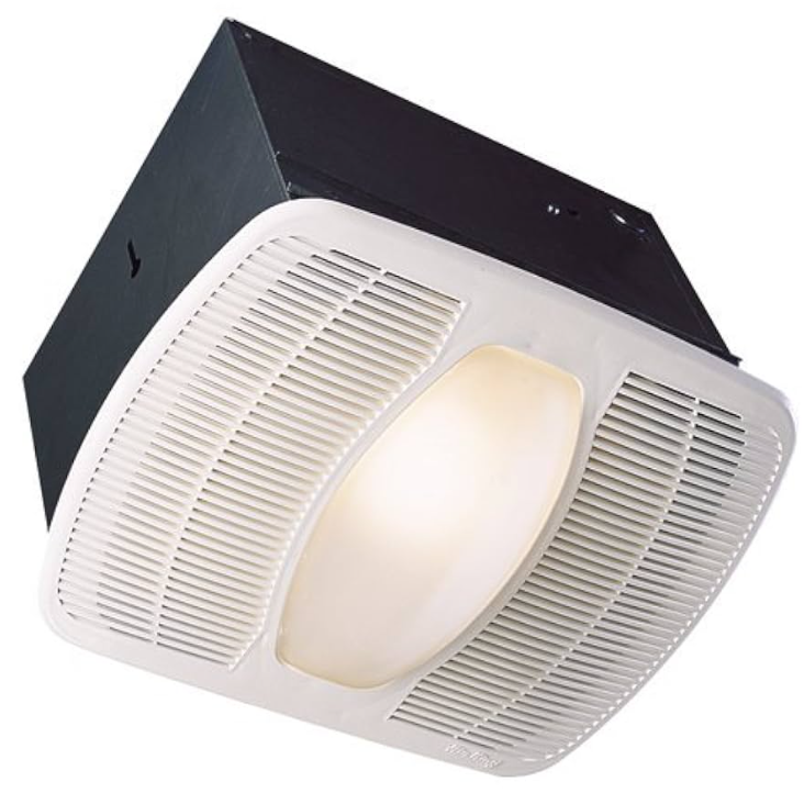
The Air King Exhaust Fan Light AK100L is a versatile and efficient solution for improving ventilation and lighting in various spaces. This product is designed to serve both as an exhaust fan and a light, making it an ideal choice for bathrooms, kitchens, and other areas where air circulation and illumination are crucial.
The AK100L is equipped with a powerful motor that ensures effective air extraction, helping to remove moisture, odors, and stale air. The integrated light feature provides ample illumination, making it a convenient option for rooms that require both ventilation and lighting.
Estimated to be priced around $100-$150, the Air King Exhaust Fan Light AK100L offers a balance of functionality and affordability. It was launched in recent years to cater to the growing demand for multi-functional home appliances.
Detailed Specifications (Key Features)
The Air King Exhaust Fan Light AK100L boasts several key features that make it a standout product in its category:
- Powerful 100 CFM motor for efficient air extraction
- Integrated 60-watt light fixture with a frosted glass lens
- UL (Underwriters Laboratories) and cUL (Canadian Underwriters Laboratories) certified for safety
- Easy installation with a mounting bracket and screws included
- Energy-efficient design to minimize power consumption
INSTALLATION INSTRUCTIONS
CAUTION: MAKE SURE POWER IS SWITCHED OFF AT THE SERVICE PANEL BEFORE STARTING INSTALLATION.
SECTION 1
Preparing the Exhaust Fan
- Unpack the fan from the carton and confirm that all pieces are present. In addition to the exhaust fan, you should have:
- Grill
- Mounting Rails
- Damper Assembly (attached)
- Instruction/Safety Sheet
- Choose the location for your fan. To ensure the best air and sound performance, it is recommended that the length of ducting and the number of elbows be kept to a minimum, the radius of each elbow be as large as possible for the installation, and that insulated hard ducting be used. This fan will require at least 8" of clearance in the ceiling or wall, and will mount through drywall up to 3/4" thick. The fan mounts between 16" and 4 on center joists using the 4 provided mounting rails.
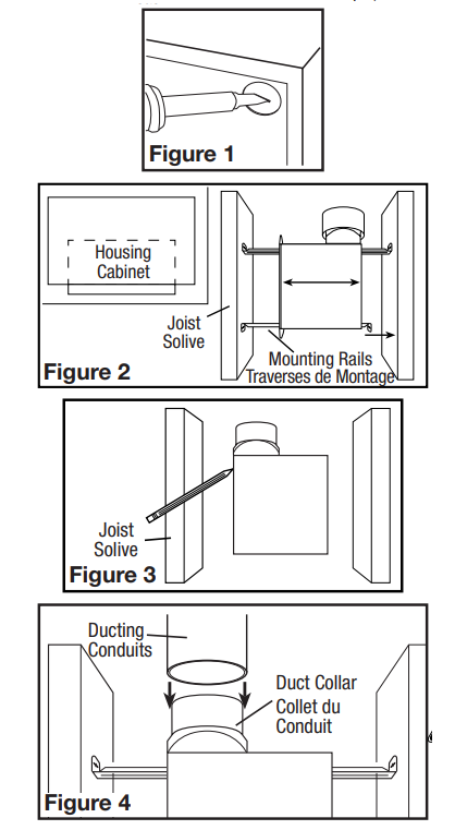
- Using a straight-blade screw driver, remove the electrical knockout from the housing (Figure 1).
SECTION 2
New Construction
- Install the rails into the mounting channel on the housing. Center the mounting channel in the slots on the housing, then , from inside the housing ,, tighten the mounting channel screws so the channel is securely in place. Position the housing next to the joist. Line up housing so that it will be flush with the finished ceiling. Secure the ends of the rails with screws or nails (not included) to the joists and slide the housing into the final position (Figure 2).
SECTION 3
Existing Construction
- Set housing in position between the joist and trace an outline onto the ceiling material (Figure 3). Set housing aside and cut the opening, being careful not to cut or damage any electrical or other hidden utilities. Install the rails into the mounting channel on the housing. Center the mounting channel in the slots on the housing, then from inside the housing tighten the mounting channel screws so the channel is securely in place. Position the housing in the previously cut hole so that it is flush with the finished ceiling. Secure the ends of the rails to the joists (Figure 2).
SECTION 4
Ducting
NOTE: 4" OR LARGER RIGID DUCT IS RECOMMENDED FOR BEST PERFORMANCE.
CAUTION: ALL DUCTING MUST COMPLY WITH LOCAL AND NATIONAL BUILDING CODES.
- Connect the ducting to the fan’s duct collar (Figure 4). Secure in place using tape or a screw clamp. Always duct the fan to the outside through a wall or roof cap. It is recommended that low-restriction termination fittings be used.
SECTION 5
- CAUTION: MAKE SURE POWER IS SWITCHED OFF AT THE SERVICE PANEL BEFORE STARTING INSTALLATION.
- CAUTION: ALL ELECTRICAL CONNECTIONS MUST BE MADE IN ACCORDANCE WITH LOCAL CODES, ORDINANCES, OR NATIONAL ELECTRICAL CODE. IF YOU ARE UNFAMILIAR WITH METHODS OF INSTALLING ELECTRICAL WIRING, SECURE THE SERVICES OF A QUALIFIED ELECTRICIAN.
NOTE: This unit may include a side access panel for wiring that does not require the removal of the fan’s blower assembly. If you choose to wire the unit from the inside, you will need to remove the blower assembly and internal wiring compartment. Both methods are equally effective.
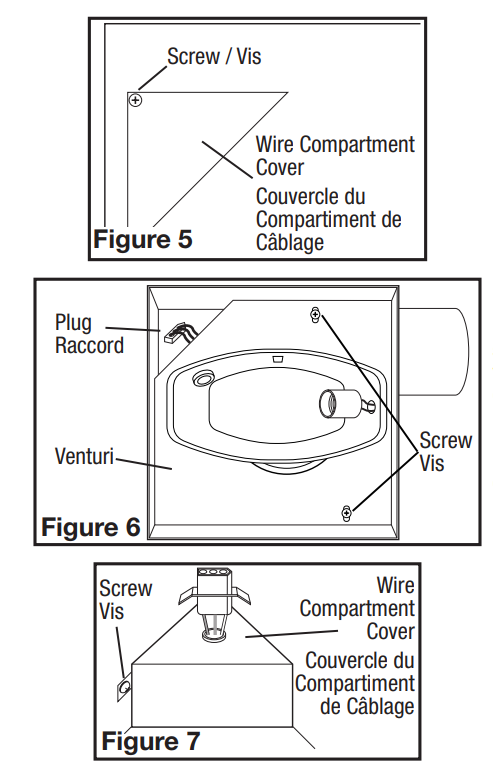
- External Wire Compartment (Not included with all models): Remove the wire compartment cover and place the cover in a secure place (Figure 5).
- Internal Wire Compartment: Remove the three screws holding the blower assembly in place and lift the assembly out of the housing (Figure 6). Remove the wire compartment cover screw and place the cover in a secure place (Figure 7).
NOTE: If the fan motor plug is connected to the fan housing receptacle, unplug it so the blower assembly can be completely removed. - Run wiring from an approved wall switch carrying the appropriate rating. One neutral (White), one round (green or bare copper), and three hot (Black, Red, Yellow leads connected to the switch, one for each function). Secure the electrical wires to the housing with an approved electrical connector. Make sure you leave enough wiring in the box to make the connection to the fan’s receptacle.
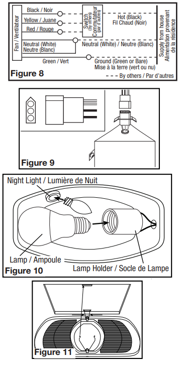
- From where you have chosen to access the fan’s junction box, connect the White wire from the house to the two White wires from the fan. Connect one Hot (Black) wire from the wall switch to the Black wire from the fan (this is the fan control). Connect the second Hot (Red) wire from the wall switch to the Red wire from the fan (this is the night light control). Connect the third Hot..
(Yellow) wire from the wall switch to the Yellow wire from the fan (this is the main light control). Connect the ground wire (green or bare copper) from the house to the Green wire from the fan (Figure 8). Use approved methods for all connections.
NOTE: The fan’s receptacle wires might need to be pulled out e the compartment for connection. Only pull the three loose wires outside of the compartment. Additional wires will be present.. - Carefully tuck the wire back inside the wire compartment and replace the wire compartment cover,, securing it with the screw that was removed earlier.
SECTION 6
Completing the Installation
- If the fan’s blower assembly was removed during the wiring process, reinstall the blower by reversing the directions in Section 5 (Wiring), Step 1b.
- Plug the fan’s quick-connect motor cord into the receptacle. This cord will only fit one way into the receptacle (Figure 9).
- Install a 100-watt maximum, type A19 medium base incandescent bulb or equivalent (not included). Install a 7-watt maximum type C7 (candelabra base) night light (not included) into the side lamp holder (Figure 10).
- Install the grill by squeezing the two ends of the springs together and installing them up into the slots on the fan’s housing. Push the grill up into position (Figure 11).
- Restore power and test your installation.
SECTION 7
Use and Care
CAUTION: MAKE SURE POWER IS SWITCHED OFF AT THE SERVICE PANEL BEFORE SERVICING THE UNIT.
- Cleaning the Grill: Remove the grill and use a mild detergent, such as dishwashing liquid, and dry with a soft cloth. NEVER USE ANY ABRASIVE PADS OR SCOURING POWDERS. Completely dry the grill before reinstalling. Refer to the instructions in Section 6,, Finishing the Installation, to reinstall l the grill.
- Cleaning the Fan Assembly: Wipe all parts with a dry cloth or gently vacuum he fan. NEVER IMMERSE ELECTRICAL PARTS IN WATER.
CAUTION: ALLOW BULBS TO COOL BEFORE REPLACING. - Changing the Lamp: Disconnect power to the unit. Remove the thrill by pulling outward on the grill and squeezing the grill springs together to release from the housing (Figure 11).
Bulb: Unscrew bulb from lamp holder and replace with a 100-watt maximum, type A19 medium base incandescent bulb or equivalent.
Night Light: Unscrew the ht light bulb from the socket and replace it with a 7-watt maximum type C7 (candelabra base) night light bulb.
LIMITED WARRANTY
- WHAT THIS WARRANTY COVERS: This product is warranted against defects in workmanship and/or materials.
- HOW LONG THIS WARRANTY LASTS: This warranty extends only to the original purchaser of the product and lasts for five (1) years from the date of original purchase or until the original purchaser of the product sells or transfers the product, whichever first occurs.
- WHAT AIR KING WILL DO: During the warranty period, Air King will, at its sole option, repair or replace any part or parts that prove to be defective or replace the whole product with the same or a comparable model. WHAT THIS WARRANTY DOES
- NOT COVER: This warranty does not apply if the product was damaged or failed because of accident, improper handling or operation, shipping damage, abuse, misuse, unauthorized repairs made or attempted. This warranty does not cover shipping costs for the return of products to Air King for repair or replacement. Air King will pay return shipping charges from Air King following warranty repairs or replacement ANY AND ALL WARRANTIES, EXPRESSED OR IMPLIED (INCLUDING, WITHOUT LIMITATION, ANY IMPLIED WARRANTY OF MERCHANTABILITY), LAST ONE YEAR FROM THE DATE OF ORIGINAL PURCHASE OR UNTIL THE ORIGINAL PURCHASER OF THE PRODUCT SELLS OR TRANSFERS THE PRODUCT, WHICHEVER FIRST OCCURS AND IN NO EVENT SHALL AIR KING’S LIABILITY UNDER ANY EXPRESS OR IMPLIED WARRANTY INCLUDE (I) INCIDENTAL OR CONSEQUENTIAL DAMAGES FROM ANY CAUSE WHATSOEVER, OR (II) REPLACMENT OR REPAIR OF ANY HOUSE FUSES, CIRCUIT BREAKERS OR RECEPTACLES. NOTWITHSTANDING ANYTHING TO THE CONTRARY, IN NO EVENT SHALL AIR KING’S LIABILITY UNDER ANY EXPRESS OR IMPLIED WARRANTY EXCEED THE PURCHASE PRICE OF THE PRODUCT, T AND ANY SUCH LIABILITY SHALL TERMINATE UPON THE EXPIRATION OF THE WARRANTY PERIOD.
- Some states and provinces do not allow limitations on how long an implied warranty lasts, or the exclusion or limitation of incidental or consequential damages, so these exclusions or limitations may not apply to you. This warranty gives you specific legal rights. You may also have other rights which vary from state to state and province to province. Proof of purchase is required before a warranty claim will be accepted.
Troubleshooting
If you encounter any issues with your Air King Exhaust Fan Light AK100L, here are some common problems and solutions:
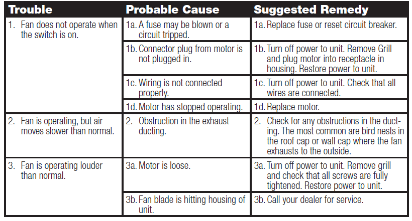
Always refer to the user manual for detailed troubleshooting instructions and safety precautions.
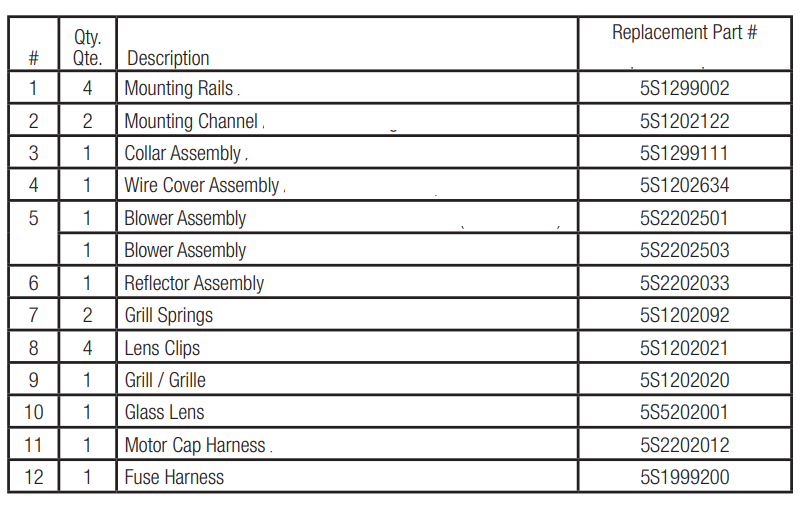
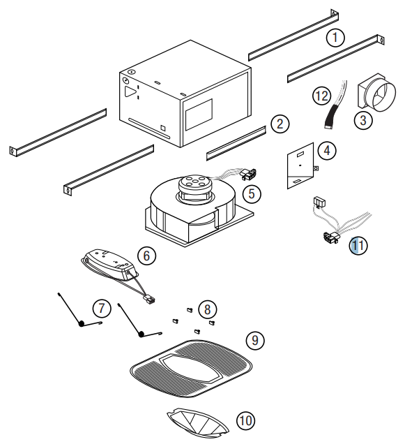
Pros & Cons
Pros:
- Multi-functional design combining ventilation and lighting
- Energy-efficient operation
- Easy installation process
- Durable construction for long-lasting performance
- UL and cUL certified for safety
Cons:
- May require professional installation if you are not comfortable with electrical work
- The light may not be as bright as some users prefer
- Noisy operation in some cases if not properly maintained
Customer Reviews
Customers generally praise the Air King Exhaust Fan Light AK100L for its ease of installation and efficient performance. Many appreciate the dual functionality of the product, which simplifies their home improvement needs. However, some users have noted that the light could be brighter and that occasional maintenance is required to keep the fan running quietly.
Most Common Complaints:
- Light brightness could be improved
- Occasional noise from the fan if not cleaned regularly
Faqs
How do I install the Air King Exhaust Fan Light AK100L?
What is the CFM rating of the Air King Exhaust Fan Light AK100L?
Is the Air King Exhaust Fan Light AK100L energy-efficient?
What type of certification does the Air King Exhaust Fan Light AK100L have?
Can I install the Air King Exhaust Fan Light AK100L myself?
How often should I clean the Air King Exhaust Fan Light AK100L?
Can I use a different wattage bulb in the Air King Exhaust Fan Light AK100L?
Is the Air King Exhaust Fan Light AK100L suitable for outdoor use?
What is the estimated lifespan of the Air King Exhaust Fan Light AK100L?
Does the Air King Exhaust Fan Light AK100L come with a warranty?
Tags
Leave a Comment