Champion 4500W Portable Inverter Generator 201318 User Guide
Content
Introduction
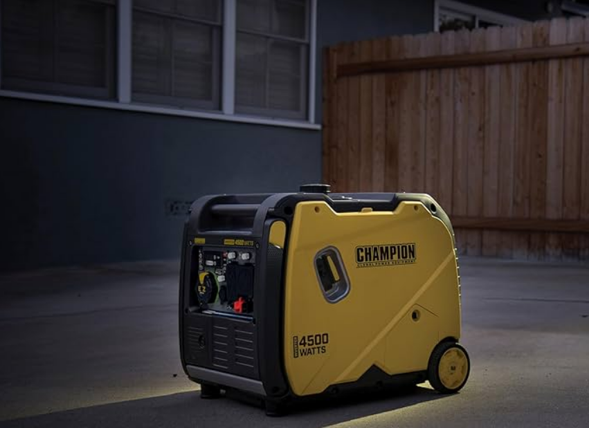
The Champion 4500W Portable Inverter Generator 201318 is a powerful and versatile solution for outdoor activities and emergency backup needs. Featuring a reliable 224cc engine, it delivers 4500 starting watts and 3650 running watts, ensuring ample power for various devices. This generator operates quietly at just 64 dBA and offers an impressive runtime of up to 17 hours at 25% load. With a price of approximately $1,595.00, it combines performance with convenience, including a wireless remote start feature.
SPECIFICATIONS
Generator Specifications
- Generator Model.. . . . . . . . . . . . . . . . . . . . . . . . . . . . . . . . . . . . . . . . . . . 201318
- Start Type.. . . . . . . . . . . . . . . . . . . . . . . . . . . . . . . . . . . . . . . . . . . . . . . . . . . Manual
- Watts (Starting/Running).. . . . . . . . . . . . . . . . . . . . . . . . . . . . . . 4500/3500
- Volts AC.. . . . . . . . . . . . . . . . . . . . . . . . . . . . . . . . . . . . . . . . . . . . . . . . . . . . . . . . . . 120
- AC Amps @ 120V.. . . . . . . . . . . . . . . . . . . . . . . . . . . . . . . . . . . . . . . . . . . . . . 29.2
- Volts DC.. . . . . . . . . . . . . . . . . . . . . . . . . . . . . . . . . . . . . . . . . . . . . . . . . . . . . . . . . . 12
- DC Amps.. . . . . . . . . . . . . . . . . . . . . . . . . . . . . . . . . . . . . . . . . . . . . . . . . . . . . . . . . . . . 8
- Frequency .. . . . . . . . . . . . . . . . . . . . . . . . . . . . . . . . . . . . . . . . . . . . . . . . . . . . . 60 Hz
- Phase.. . . . . . . . . . . . . . . . . . . . . . . . . . . . . . . . . . . . . . . . . . . . . . . . . . . . . . . . . Single
- Grounding Type.. . . . . . . . . . . . . . . . . . . . . . . . . . . . . . . . . . . . .Neutral Floating
- Weight.. . . . . . . . . . . . . . . . . . . . . . . . . . . . . . . . . . . . . . . . . . . . 92.2 lb. (41.8 kg)
- Length.. . . . . . . . . . . . . . . . . . . . . . . . . . . . . . . . . . . . . . . . . . . . . 23.2 in. (59 cm)
- Width .. . . . . . . . . . . . . . . . . . . . . . . . . . . . . . . . . . . . . . . . . . . . . . 17.7 in. (45 cm)
- Height.. . . . . . . . . . . . . . . . . . . . . . . . . . . . . . . . . . . . . . . . . . . . . . . 20.1 in. (51 cm)
Engine Specifications
- Model.. . . . . . . . . . . . . . . . . . . . . . . . . . . . . . . . . . . . . . . . . . . . . . . . . . . . . . R210-VP
- Displacement.. . . . . . . . . . . . . . . . . . . . . . . . . . . . . . . . . . . . . . . . . . . . . . . . . 212 cc
- Type.. . . . . . . . . . . . . . . . . . . . . . . . . . . . . . . . . . . . . . . . . . . . . . . . . . . 4-Stroke OHV
Spark Plug
- OEM Type.. . . . . . . . . . . . . . . . . . . . . . . . . . . . . . . . . . . . . . . . . . . . . . . . . . . . . F6RTC
- Replacement Type.. . . . . . . . . . . . . . . . . . . . . .NGK BPR6ES or equivalent
- Gap.. . . . . . . . . . . . . . . . . . . . . . . . . . . . . . . . . .0.028-0.031 in. (0.7-0.8 mm)
Valve
- Intake Clearance.. . . . . . . . . . . . . . . . . 0.002-0.006 in. (0.05-0.15 mm)
- Exhaust Clearance.. . . . . . . . . . . . . . . 0.002-0.006 in. (0.05-0.15 mm)
Oil Specifications
DO NOT OVERFILL.
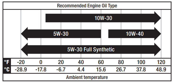
- Type.. . . . . . . . . . . . . . . . . . . . . . . . . . . . . . . . . . . . . . . . . . . . *See following chart
- Capacity.. . . . . . . . . . . . . . . . . . . . . . . . . . . . . . . . . . . . . . . 16.9 fl. oz. (500 ml)
NOTICE
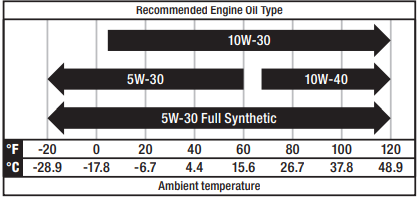
Temperature will affect engine oil and engine performance. Change the type of engine oil used based on temperature shown in the “Recommended Engine Oil Type” table.
Fuel Specifications
Use unleaded gasoline with a minimum octane rating of 87 and an ethanol content of 10% or less by volume. DO NOT USE E15 or E85. DO NOT OVERFILL.
- Gasoline Capacity ................................. 2.25 gal. (8.5 L)
Temperature Specifications
- Starting Temperature Range (°F/°C) ........... 5 to 104/-15 to 40
NOTICE
An important message about temperature: Your product is designed and rated for continuous operation at ambient temperatures up to 104°F (40°C). When needed, it may be operated at temperatures ranging from 5°F (-15°C) to 122°F (50°C) for short periods of time. If exposed to temperatures outside this range during storage, it should be brought back within this range before operation. In any event, the product must always be operated outdoors, in a well-ventilated area and away from doors, windows and vents.
CONTROLS AND FEATURES
Read this operator’s manual before operating your generator. Familiarize yourself with the location and function of the controls and features. Save this manual for future reference.
Generator
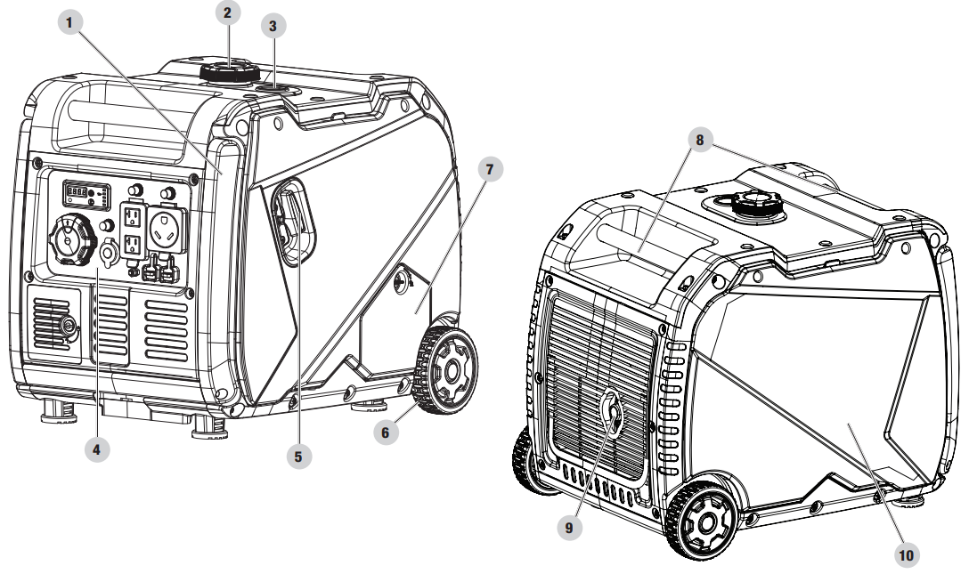
- Folding Handle – Used to move unit by lifting and rolling on wheels. Do not use to lift or carry the unit.
- Fuel Cap – Remove to add fuel.
- Fuel Gauge
- Control Panel – See Control Panel section.
- Recoil Starter – Used to manually start the engine.
- Never Flat Wheels – 5 in. (12.7 cm)
- Oil Fill Access Cover
- Carrying Handle(s) – Used to lift or carry the unit.
- Muffler
- Maintenance Cover
Control Panel
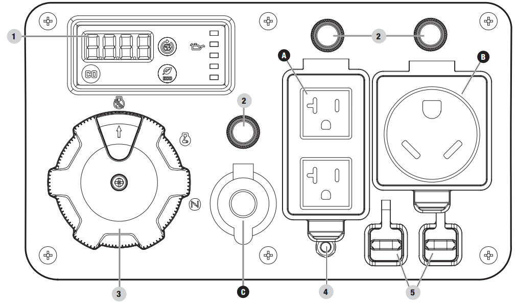
- Intelligauge with Power Meter – See Intelligauge section.
- Circuit Breakers (Push Reset) – Protects the generator against electrical overloads.
- EZ Start Dial – Used to start, stop and choke the generator.
- Ground Terminal – Consult an electrician for local grounding regulations.
- Parallel Outlets – Used to parallel two inverters together for increased power output. (parallel kit sold separately).
| RECEPTACLES | ||
A | (2×) 120V AC, 20A (NEMA 5-20R) May be used to supply electrical power for operation of 120 Volt AC, 20 Amp, single phase, 60 Hz electrical loads. | |
B |  | 120V AC, 29.2A RV (NEMA TT-30R) May be used to supply electrical power for operation of 120 Volt AC, 29.2 Amp, single phase, 60 Hz electrical loads. |
C |  | 12V DC, 8A (Regulated Automotive) May be used to supply electrical power for operation of 12 Volt DC, 8 Amp electrical loads. |
WARNING: When charging a device, do not place on the exhaust side of the generator. Extreme heat caused by exhaust can damage the device and cause a potential fire hazard. Prolonged exposure to engine exhaust can cause serious injury or death.
Intelligauge with Power Meter and CO Shield
Five mode digital meter for displaying voltage, frequency, session run time, total run time and power output.

- CO Shield LED – The CO Shield technology monitors for accumulation of poisonous carbon monoxide (CO) gas produced by engine exhaust when the generator is running. If CO Shield® detects elevated levels of CO gas, it automatically shuts off the engine.
- Economy Mode Button – Enables/disables automatic idle control.
- AC Overload Reset Button – Used to re-energize receptacles after overload fault.
- Low Oil Warning Indicator Light – When ON, engine will shut down and not run. Check oil level.
| MODE | DESCRIPTION | ||
1 |
Voltage (V) | Output voltage of the generator. | |
Example: 120 volts |  | ||
2 |
Frequency (H) | Output frequency in hertz. | |
Example: 60.0 hertz |  | ||
3 |
Run Time (R) | Run time of the generator for the current session. | |
Example: 6 hours |  | ||
4 |
Total Run Time | Total run time of the generator since first operation. | |
Example: 16 hours |  | ||
5 |
Power Meter | Power Output percentage. | |
| The output power will be displayed at all times on the right side. The output power percentage shown is based on the electrical load connected to the generator. As the output increases, more green LED lights are shown. In the event of an overload, all output LED lights, including a red LED, will be shown and the display flashes “EEEE” three times per second. | |||
Parts Included
Accessories
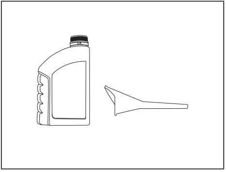
- Engine Oil ...................................... 16.9 fl. oz. (500 ml)
Oil Funnel ........................................................... 1
Tools Included
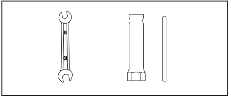
- 8/10 mm Wrench ................................................... 1
Spark Plug Wrench ................................................. 1
Description
The Champion 4500W Portable Inverter Generator 201318 features a robust 212cc single-cylinder OHV engine that provides reliable power output. The inverter technology ensures clean power with less than 3% THD, making it suitable for sensitive electronics such as laptops, smartphones, and televisions. The generator is designed with a compact and lightweight frame, making it easy to transport and store. It also includes multiple outlets to accommodate different types of appliances and tools.
The generator comes with a built-in parallel kit, allowing you to connect two generators for increased power output. Additionally, it has an electric start with a recoil backup, ensuring easy startup even in cold conditions. The intuitive control panel and LED indicators provide clear visibility of the generator's status.
ASSEMBLY
Your generator requires some assembly. It must be properly serviced with fuel and oil before operation.
Unpacking
- Set the shipping carton on a solid, flat surface.
- Remove everything from the carton except the generator.
- By lifting up on the carrying handles, carefully remove the generator from the box (two people lifting is recommended).
Remove Shipping Support Hardware
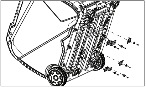
To protect the generator during shipping, support hardware has been installed between the engine and frame. This hardware MUST BE REMOVED BEFORE adding oil or gasoline to the generator.
NOTICE: DO NOT attempt to run the generator without first removing the shipping support hardware. Damage to the generator as a result of not removing the hardware will void the warranty.
- BEFORE filling the engine with oil or gasoline, tip the generator onto the muffler side. Tip onto the flattened cardboard box the generator came in or another protective surface so as to not scratch the enclosure.
- Remove the two bolts, four nuts and mounting plates from the bottom side of the generator using the included 8/10 mm wrench. Bolts, nuts, and spacers can be discarded.
Tip the generator upright.
Add Engine Oil
WARNING: DO NOT attempt to crank or start the engine before it has been properly filled with the recommended type and amount of oil. Damage to the generator as a result of failing to follow these instructions will void your warranty.
NOTICE: The generator rotor has a sealed, pre-lubricated ball bearing that requires no additional lubrication for the life of the bearing.
NOTICE: The recommended oil type for typical use is 10W-30 automotive oil. However, using the listed conventional oils shown in the “Recommended Engine Oil Type” chart may be used for typical use including the first 5 hours of the break-in run time period of the engine.
If running generator in extreme temperatures.
- Place the generator on a flat, level surface.
Turn the oil access cover fastener to the unlocked position and remove the cover.
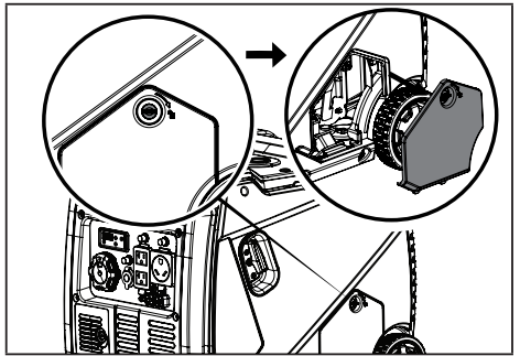
- Remove oil fill cap/dipstick to add oil.
Using a funnel, add up to 16.9 fl. oz. (500 ml) of oil (included).
DO NOT OVERFILL. Replace oil fill cap/dipstick and secure maintenance cover.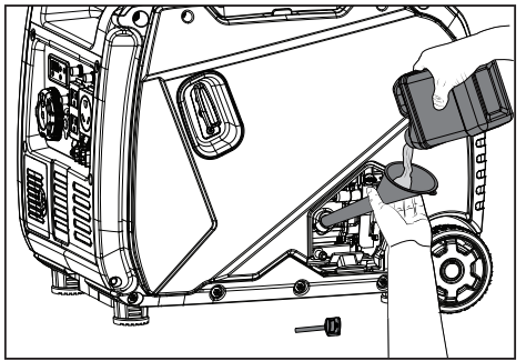
Check engine oil level before each use and add as needed.
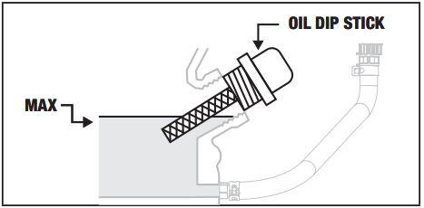
NOTICE
Once oil has been added, a visual check should show oil about 1-2 threads from running out of the fill hole.
When using the dipstick to check oil level, DO NOT screw in the dipstick while checking.
NOTICE
Check oil level often during the break-in period. Refer to the Maintenance section for recommended service intervals.
CAUTION
This engine is equipped with a low oil shut-off and will stop when the oil level in the crankcase falls below the threshold level.
NOTICE
The first 5 hours of run time are the break-in period for the unit. During the break in period stay at or below 50% of the running watt rating and vary the load occasionally to allow stator windings to heat and cool. Adjusting the load will also cause engine speed to vary slightly and help seat piston rings. After the 5 hour break-in period, change the oil.
NOTICE
Synthetic oil may be used after the 5 hour initial break-in period. Using synthetic oil does not decrease the recommended oil change interval. Full synthetic 5W-30 oil will aid in starting in cold ambient < 41º F (5º C) temperatures.
Add Fuel
DANGER
Gasoline vapors are highly flammable and extremely explosive.
- DO NOT light or smoke cigarettes. Fire or explosion can cause severe burns or death.
- Only fill or drain fuel outdoors in a well-ventilated area.
- DO NOT pump gasoline directly into the generator. Use an approved container to transfer the fuel to the generator.
- Never use a gasoline container, gasoline tank, or any other fuel item that is broken, cut, torn or damaged.
- DO NOT overfill the gasoline tank. Always keep fuel away from sparks, open flames, pilot lights, heat and other sources of ignition.
Use clean, fresh, regular unleaded gasoline with a minimum octane rating of 87 and an ethanol content of 10% or less by volume. ![]()
DO NOT mix oil with gasoline.
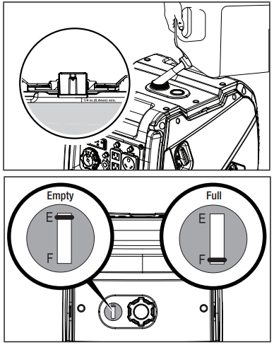
- Remove the gasoline cap.
- Slowly add gasoline to the tank. Tank is full when gasoline reaches red circle on screen. DO NOT OVERFILL. Gasoline can expand after filling. A minimum of ¼ in. (6.4 mm) of space left in the tank is required for gasoline expansion, although more than ¼ in. (6.4 mm) is recommended. Gasoline can be forced out of the tank as a result of expansion if overfilled, and can affect the stable running condition of the generator.
- The approximate fuel level is shown on the fuel gauge on top of the fuel tank.
- Screw on the gasoline cap and wipe away any spilled fuel.
CAUTION
Use unleaded gasoline with a minimum octane rating of 87 and an ethanol content of 10% or less by volume.
- DO NOT light cigarettes or smoke when filling the tank.
- DO NOT mix oil and gasoline.
- DO NOT overfill the tank. Fill tank to approximately ¼ in. (6.4 mm) below the top of the tank to allow for gasoline expansion.
- DO NOT pump gasoline directly into the generator at the pump. Use an approved fuel container to transfer the gasoline to the generator.
- DO NOT fill tank indoors.
- DO NOT fill tank when the engine is running or hot.
WARNING: Pouring gasoline too fast through the fuel screen may result in gasoline splashing over the generator and operator while filling.
NOTICE: The generator engine works well with 10% or less ethanol blended gasoline. When using ethanol-gasoline blends there are some issues worth noting:
- Ethanol-gasoline blends can absorb more water than gasoline alone.
- These ethanol blends can eventually separate, leaving water or a watery goo in the tank, fuel valve and carburetor. The compromised gasoline can be drawn into the carburetor and cause damage to the engine and/or create potential hazards.
- If a fuel stabilizer is used, confirm that it is formulated to work with ethanol-gasoline blends.
- Any damages or hazards caused by using ethanol blended gasoline higher than 10% by volume, improperly stored gasoline, and/or improperly formulated stabilizers, are not covered by manufacturer’s warranty.
It is advisable to always shut off the gasoline supply and run the engine to starvation after each use. See Storage instructions for extended non-use.
Grounding
Your generator must be properly connected to an appropriate ground to help prevent electric shock.
WARNING
Failure to properly ground the generator can result in electric shock.
A ground terminal connected to the panel of the generator has been provided (see Controls and Features for terminal location). For remote grounding, connect a length of heavy gauge (12 AWG minimum) copper wire between the generator ground terminal and a copper rod driven into the ground. We strongly recommend that you consult with a qualified electrician to ensure compliance with local electrical codes.
Neutral Floating
- Neutral circuit IS NOT electrically connected to the frame/ground of the generator.
- The generator (stator winding) is isolated from the frame and from the AC receptacle ground pin.
- Electrical devices that require a grounded receptacle pin connection will not function if the receptacle ground pin is not functional.
Neutral Bonded to Frame
- Neutral circuit IS electrically connected to the frame/ground of the generator.
- The generator system ground connects lower frame cross-member below the alternator. The system ground is connected to the AC neutral wire.
See your Specifications section for specified type of grounding.
OPERATION
- CO Shield - Carbon Monoxide (CO) Detection and Auto-shutoff System
- CO Shield technology monitors the accumulation of carbon monoxide (CO), a poisonous gas produced by engine exhaust when the generator is running. If CO Shield® detects unsafe elevated levels of CO gas, it automatically shuts off the engine.
- CO SHIELD IS NOT A SUBSTITUTE FOR AN INDOOR CARBON MONOXIDE ALARM OR FOR INDOOR OPERATION.
- DO NOT allow engine exhaust fumes to enter a confined area through windows, doors, vents or other openings.
Generators must ALWAYS be used outdoors, far away from occupied buildings with engine exhaust pointed away from people and buildings.
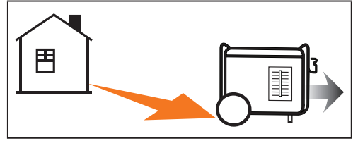
If misused and operated in an unapproved and unsafe location that results in the accumulation of poisonous CO gas inside an enclosed or partially enclosed space, for example a house, garage or a garage with the door partially open, CO Shield® will automatically shut off the generator and then will illuminate a blinking red LED light. Read the action label for next steps.
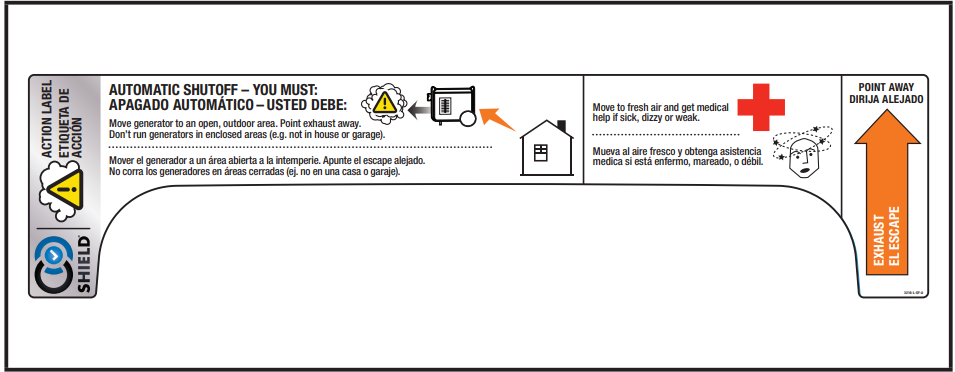
In the event of an engine shut off, when you approach the generator to investigate, a blinking red LED light in the CO Shield® area provides notification that the generator shut off due to an accumulating CO hazard. The red LED light will blink for at least five (5) minutes after an engine shut off event.
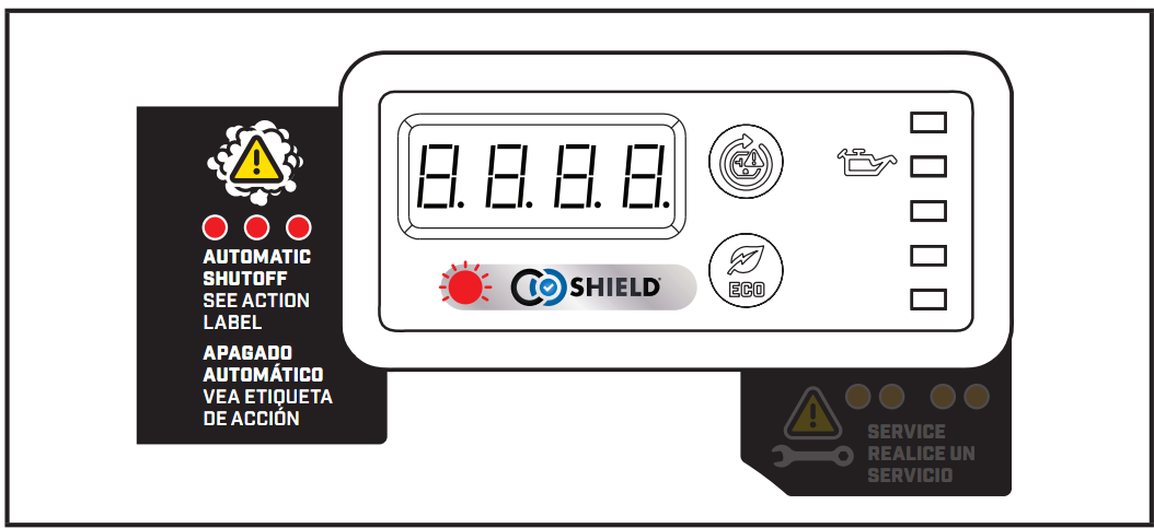
- Move the generator far away to an open, outdoor area and point the exhaust away from people and buildings. Once relocated to a safe area, the generator can be restarted, and the proper electrical connections made. Introduce fresh air and ventilate the location where the generator shut off.
- When restarting, the red and yellow LED will blink ten (10) times simultaneously to indicate the LED is working.
NOTICE: This blinking LED light does not indicate CO Shield® is working, as CO Shield® is working at all times when the generator is running. Also, the LED light will not blink (10) times if the generator was restarted within 1 minute after it was manually shut off. This does not occur if generator shut off from a high CO event. If CO Shield® system experiences a fault and no longer provides protection, the generator is shutoff automatically and the yellow LED light will blink for at least five (5) minutes to notify you of the fault.
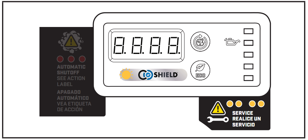
NOTICE
CO Shield will detect the accumulation of carbon monoxide (CO) from other fuel burning sources such as engine powered equipment, or propane heaters used in the area of operation. If another generator is used and the exhaust stream is pointed at a CO Shield equipped generator, the CO Shield may initiate a shutoff due to rising carbon monoxide (CO) levels. This is not a fault. Poisonous carbon monoxide (CO) has been detected. You must take action to move and direct the generator exhaust stream to better disperse carbon monoxide (CO) far away from people or buildings.
DANGER
Tampering with the CO Shield® system will result in a hazardous condition and will void your warranty.
Removing the CO Shield® module will not allow the generator to start.
Generator Location
WARNING
- NEVER operate the generator inside any building, garage, basement, crawlspace, shed, enclosure or compartment, including a generator compartment of a recreational vehicle.
- NEVER operate or start the generator in the back of an SUV, camper, trailer, truck bed (regular sides, flat or other configuration), under staircases, stairwells, next to walls or buildings or in any other location that will not allow for adequate cooling of the generator or for the proper exit of the exhaust flow from the muffler system.
- DO NOT operate or store the generator in wet weather conditions such as rain or snow. Using a generator in wet conditions could result in serious injury or death due to electrocution.
- In some state’s generators may be required to be registered with the local utility company when used at construction sites and may be subject to additional rules and regulations, consult your local municipal authority.
- Generators should always be operated on a flat, level surface at all times (even when not in operation).
- Generators must have a minimum of 5 feet (1.5 m) of clearance from all combustible material.
- Generators must also have a minimum of 3 feet (91.4 cm) of air flow clearance on all sides to allow for adequate performance cooling, maintenance and servicing.
- Always place the generator in a well-ventilated area. NEVER place the generator near air intake vents or where exhaust fumes could be drawn into occupied or confined spaces.
- Always carefully consider wind and air currents when positioning generator.
- Always allow generators to properly cool before transport or for storage purposes.
- Failure to follow proper safety precautions may result in personal injury, damage to the generator and void the manufacturer’s warranty.
WARNING
- During operation the muffler and exhaust fumes will become hot. If adequate cooling and breathing space are not supplied, or if the generator is blocked or enclosed, temperatures can become extremely heated and may lead to fire.
WARNING
- Do not expose to rain or use in damp locations.
- Keep all objects a minimum of 5 feet (1.5m) away from the generator at all times. Heat from the muffler surface and exhaust gas stream can ignite combustible materials.
WARNING
- If you must operate in rain or damp locations, DO NOT operate without proper protection of the electrical components.
Use of a safety canopy that is fire retardant and will provide proper air ventilation for the engine exhaust gas stream may be used.
Surge Protection
Electronic devices, including computers and many programmable appliances use components that are designed to operate within a narrow voltage range and may be affected by momentary voltage fluctuations. While there is no way to prevent voltage fluctuations, you can take steps to protect sensitive electronic equipment.
- Install UL1449, CSA-listed, plug-in surge suppressors on the outlets feeding your sensitive equipment.
- Surge suppressors come in single- or multi-outlet styles. They’re designed to protect against virtually all short-duration voltage fluctuations.
Starting the Engine
- Make certain the generator is on a flat, level surface.
- Disconnect all electrical loads from the generator. Never start or stop the generator with electrical devices plugged in or turned on.
Cold Engine Start Move the EZ Start dial to the “CHOKE” position.
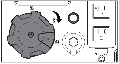
Pull the recoil cord slowly until resistance is felt and then pull rapidly.
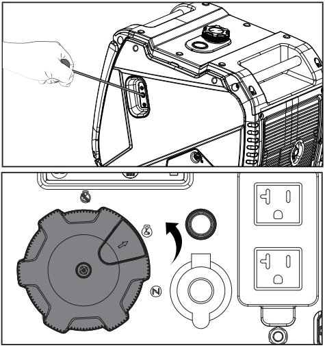
- As the engine warms up, turn the EZ Start dial to the “RUN” position.
Warm Engine Start
- Turn the EZ Start dial to the “RUN” position.
Pull the recoil cord slowly until resistance is felt and then pull rapidly.
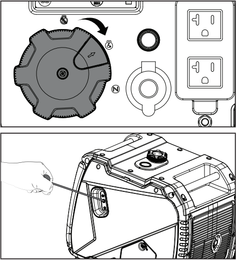
NOTICE
For gasoline restarts with hot engine in hot ambient temperature >86°F (30°C): Move the EZ Start dial to the “CHOKE” position for only one start attempt. If generator does not start after first attempt, move the EZ Start dial to the “RUN” position for the next three attempts. Too much choke leads to spark plug fouling and engine flooding. This will cause the engine not to start.
NOTICE
For gasoline starting in standard ambient temperature > 59°F (15°C): Move the EZ Start dial to the “CHOKE” position for three start attempts. If generator does not start after three attempts, move the EZ Start dial to the “RUN” position for the next three attempts. Too much choke leads to spark plug fouling and engine flooding. This will cause the engine not to start.
NOTICE
For gasoline starting in cold ambient temperature < 59°F (15°C): Keep the EZ Start dial in the “CHOKE” position until engine starts. As soon as the engine starts and runs smoothly move the EZ Start dial to the “RUN” position. In extreme cold temperatures, this may take several seconds.
NOTICE
If the engine starts but does not continue to run make certain that the generator is on a flat, level surface. The engine is equipped with a low oil sensor that will prevent the engine from running when the oil level falls below a critical threshold.
Connecting Electrical Loads
Let the engine stabilize and warm up for a few minutes after starting.
Plug in and turn on the desired 120 or 240 (if applicable) Volt AC single phase, 60 Hz electrical loads.
- DO NOT connect 3-phase loads to the generator.
- DO NOT overload the generator.
- Use only a high quality, insulated, compatible (3-wire or 4- wire) grounded cord set rated equal to or greater (volts and amps) than the receptacle plugging into.
WARNING
- Always remember to plug your appliances directly into the generator and do not plug the generator power cord into any electrical outlet or connect to the circuit breaker panel in your home. Connecting a generator to your home’s electric utility company’s power lines, or to another power source, called ‘backfeeding’ is a dangerous practice that is illegal in many states and municipalities.
- This action if done incorrectly could damage your generator, appliances and could cause serious injury or death to you or a utility worker when attempting to restore power during an outage occurrence in the neighborhood who may then unexpectedly encounter high voltage on the utility line and suffer a fatal shock.
- Whether injuries occur or not, if installed incorrectly and not to applicable laws and codes, you may be subject to fines or the utility company may disconnect your home power should this practice be found in your home.
- If the generator will be connected to a building electrical system, those connections must isolate the generator power from the utility power. You are responsible for ensuring your generator’s electricity does not backfeed into the electric utility power lines. These connections must comply with all applicable laws and codes – Consult your local utility company or a qualified electrician to properly install this connection.
Do Not Overload Generator Capacity
Follow these simple steps to calculate the running and starting watts necessary for your purposes:
- Select the electrical devices you plan on running at the same time.
- Total the running watts of these items. This is the amount of power you need to keep your items running.
- Identify the highest starting wattage of all devices identified in step 1. Add this number to the number calculated in step 2. Starting wattage is the surge of power needed to start some electric driven equipment. Following the steps listed under “Power Management” will guarantee that only one device will be starting at a time.
If the generator power output is cut off due to an overload condition indicated by the AC overload blinking light, lower the load by unplugging one or more items, then press the AC overload reset button before restarting the generator for continued normal operation.
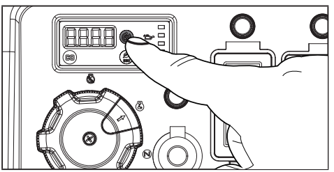
Power Management
Use the following formula to convert voltage and amperage to watts:
Volts × Amps = Watts
To prolong the life of your generator and attached devices, follow these steps to add electrical load:
- Start the generator with no electrical load attached.
- Allow the engine to run for several minutes to get up to temperature.
- Make sure all circuit breakers are set to the run position.
- Plug in and turn on the first item. It is best to attach the item with the largest load first.
- Allow the engine to stabilize.
- Plug in and turn on the next item.
- Allow the engine to stabilize.
- Repeat steps 6-7 for each additional item.
NOTICE
Never exceed the specified capacity when adding loads to the generator.
Eco (Economy) Mode
The Eco Mode button can be activated to turn on economy control in order to minimize fuel consumption and noise while operating the unit during times of reduced electrical output. Eco Mode allows the engine speed to idle during periods of non-use.
The engine speed returns to normal when an electrical load is connected. When the economy switch is off, the engine runs at normal speed continuously.
_mode_champion_4500w_portable_inverter_generator_201318.png)
CAUTION: For periods of high electrical load or momentary fluctuations, the Eco Mode should be off.
12V DC Automotive Style Outlet
The 12V DC outlet(s) can be used with supplied accessories and other commercially available 12V DC automotive style plugs. Confirm the input voltage range of your item is at least 12-24V DC.
WARNING
When charging a device, do not place on the exhaust side of the generator. Extreme heat caused by exhaust can damage the device and cause a potential fire hazard. Prolonged exposure to engine exhaust can cause serious injury or death.
Battery Charging
- Before connecting the battery charging cable (not included) to a battery that is installed in a vehicle, disconnect the vehicle battery ground cable from the negative (–) battery terminal.
- Plug the battery charging cable into the 12V DC receptacle of the generator.
- Connect the red (+) battery charger lead to the red (+) battery terminal.
- Connect the black (–) battery charger lead to the black (–) battery terminal.
- Start the generator.
Important: The 12V DC outlet is ONLY to be used with supplied accessories and other commercially available 12V DC automotive-style plugs. Be sure all electric devices including the lines and plug connections are in good condition before connection to the generator.
WARNING
Do not start the vehicle while the battery charging cable is connected and the generator is running. It will not give the battery a boost of power. The vehicle or the generator may be damaged. Charge only vented wet lead acid batteries. Other types of batteries may burst, causing personal injury or damage.
NOTICE
Be sure all electric devices including the lines and plug connections are in good condition before connection to the generator.
Parallel Operation
The Champion model 201318 is parallel ready and can be operated in parallel with another Champion unit to increase the total available electrical power. A Champion model 100319 parallel kit (sold separately) is required for parallel operation.
Stopping the Engine
- Turn off and unplug all electrical loads. Never start or stop the generator with electrical devices plugged in or turned on.
- Let the generator run at no-load for several minutes to stabilize internal temperatures of the engine and generator.
Turn the EZ Start dial counterclockwise to the “STOP” position.
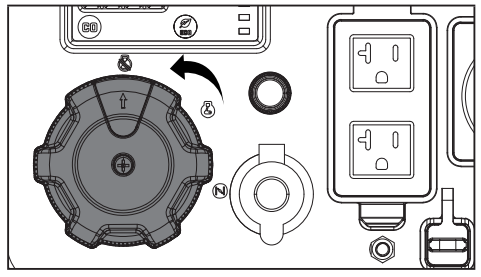
Important: Always ensure that the EZ Start dial is in the “OFF” position when the generator is not in use.
NOTICE: If the generator will not be used for a period of two (2) weeks or longer, please see the Storage section for proper engine and fuel storage.
Moving the Generator
CAUTION
- NEVER lift or carry the generator using the folding handle.
- NEVER tilt sideways while moving the generator.
- ALWAYS place the generator on its wheels in the upright position.
- ALWAYS turn the generator off and ensure the fuel valve is closed.
- ALWAYS make sure engine and muffler are cooled down before the generator can be handled safely (typically 15-30 minutes).
WARNING
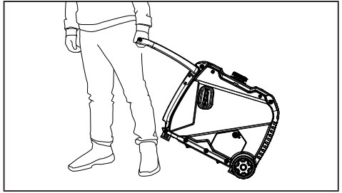
The folding handle is not long enough to hold and walk with a full stride when moving the generator. Always side step as you walk to avoid injury to your heels and/or feet. Failure to follow these instructions could result in personal injury or damage to the generator.
- Begin by raising the folding handle, found on opposite side of wheels.
- Using the handle, tilt the end of the generator slightly off the ground until balanced on the wheels.
While maintaining balance, roll the generator to the desired location.
Operation at High Altitude
The density of air at high altitudes is lower than at sea level. Engine power is reduced as the air mass and air-fuel ratio decrease. Engine power and generator output will be reduced approximately 3½% for every 1000 ft. of elevation above sea level. At high altitudes increased exhaust emissions can also result due to the increased enrichment of the air fuel ratio. Other high altitude issues can include hard starting, increased fuel consumption and spark plug fouling.
To alleviate high altitude issues other than the natural power loss, CPE can provide a high altitude carburetor main jet. The alternative main jet and installation instructions can be obtained by contacting our Technical Support Team. Installation instructions are also available in the Technical Bulletin area of the CPE website.
The part number and recommended minimum altitude for the application of the high altitude carburetor main jet is listed in the following table. In order to select the correct high altitude main jet it is necessary to identify the carburetor model. For this purpose, a code is stamped on the side of the carburetor. Select the correct high altitude jet part number corresponding to the carburetor code found on your particular carburetor.
| Carb. Code | High Alt. Jet Part Number | Min. Altitude |
16100- 000021 | 16161-000004 | 3000 ft. (914 m) |
| 16161-000010 | 6000 ft. (1829 m) |
WARNING
Operation using the alternative main jet at elevations lower than the recommended minimum altitude can damage the engine. For operation at lower elevations, the originally supplied standard main jet must be used. Operating the engine with the wrong engine configuration at a given altitude may increase its emissions and decrease fuel efficiency and performance.
Setup Guide
To operate the Champion 4500W Portable Inverter Generator 201318,
- Start by ensuring it is placed on a flat surface away from any flammable materials.
- Add the recommended type and amount of engine oil before the first use. Fill the fuel tank with the specified type of gasoline, making sure not to overfill.
- For electric start, insert the battery into the battery compartment if not already installed.
- Turn the choke to the "start" position and press the electric start button. If the generator does not start, use the recoil start as a backup.
- Once started, adjust the choke to the "run" position.
- Connect your appliances to the appropriate outlets, ensuring the total load does not exceed the generator's capacity.
TROUBLESHOOTING
Problem | Cause | Solution |
Engine willnot start. | No fuel. | Add fuel. |
Faulty spark plug. | Clean and adjust spark plug or replace. | |
Low oil level. | Fill crankcase to the proper level. | |
Place generator on a flat, level surface. | ||
Spark plug wire loose. | Attach wire to spark plug. | |
Fuel valve is closed. | Open fuel valve. | |
EZ Start dial OFF. | Turn EZ StartdialON. | |
Old fuelor water in fuel. | Drain fuel and replacewith fresh fuel. | |
Flooded with fuel. | Let unit stand for 10 mins. | |
CO Shield® module has been removed or tampered with. | Re-install module or contact technical support. | |
Engine starts but runs roughly. | Choke in the wrong position. | Move EZ Start Dial to the RUN position. |
Dirty air filter. | Clean or replace air filter. | |
Dirty fuel valve. | Clean the fuel valve. | |
Clogged spark arrestor. | Clean spark arrestor. | |
Engine will not start electrically. | Generator battery is dead. | Recharge generator battery. |
Engine shuts down during operation. | Out of fuel. | Fill fueltank. |
Low oil level. | Fill crankcase to the proper level. Place generator on a flat,level surface. | |
If equipped, whenCO Shield® shutoffs occur due to accumulating carbon monoxide (CO) andif the redLED light blinks on the panel. | Move generator to an open, outdoor area. Point exhaust away from people and buildings. Move to fresh air and get medicalhelp if sick,dizzy, or weak. Make sure thereare no objectscreating obstructions within 5 feet of the generator. Obstructions in the vicinity of the generator may trap carbon monoxide emissions near the generatorand cause the engine to shutoff. If the generator’s exhaust is facing intothe wind, the exhaust may be blown back into thegenerator’s operating area, creating an accumulation of CO emissions and triggering an engine shutoff. To avoidan engine shutoff, turn the generator 45° in eitherdirection to allow the exhaust emissions to blow away from the generator. If engine shutoffevents continue, readjust and align the exhaust with the wind direction to blow away from the generator. | |
If equipped, whenCO Shield® shutoffs occur due to system fault and if the yellow LED light blinkson the panel. | Start by confirming yellow LED lightblinks when/ if generator shuts off. If CO Shield continues to sense the fault and shuts off, contact technical support. | |
Clogged spark arrestor. | Clean spark arrestor. |
Engine starts and shuts off right away. |
If equipped, whenCO Shield® shutoffs occur due to accumulating carbon monoxide (CO) andif the redLED light blinks on the panel. | Move generator to an open, outdoor area. Point exhaust away from people and buildings. Move to fresh air and get medicalhelp if sick,dizzy, or weak. Make sure thereare no objectscreating obstructions within 5 feet of the generator. Obstructions in the vicinity of the generator may trap carbon monoxide emissions near the generatorand cause the engine to shutoff. If the generator’s exhaust is facing intothe wind, the exhaust may be blown back into thegenerator’s operating area, creating an accumulation of CO emissions and triggering an engine shutoff. To avoidan engine shutoff, turn the generator 45° in eitherdirection to allow the exhaust emissions to blow away from the generator. If engine shutoffevents continue, readjust and align the exhaust with the wind direction to blow away from the generator. |
If equipped, whenCO Shield® shutoffs occur due to system fault and if the yellow LED light blinkson the panel. | Start by confirming yellowLED light blinkswhen/ if generator shuts off. If CO Shield continues to sense the faultand shuts off, contact technical support. | |
Both CO Shield® LEDs not blinking 10 times upon start up. | Starting the generator within 1 minute after being manually shutoff, not a CO shutoff event. | Wait 1 minute before trying to restart the generator. The LEDs should then blink ten (10) times. |
Generator cannot supply enough power or overheating. | Generator is overloaded. | Review load and adjust. See “Connecting Electrical Loads.” |
Dirty air filter. | Clean or replace air filter. | |
Choke in wrong position. | Move EZ Start Dial to the RUN position. | |
Engine is running butnoAC output. | Poor cord connection. | Check all connections. |
Circuit breaker is open. | Reset circuit breaker. Check all circuit breakers. | |
Loose wiring. | Inspect and tighten wiring connections. | |
AC Overload: Button illuminated red | Reduce AC load and press Overload Reset Button until illuminated green. | |
Other. | Contact the help line. |
Engine hunts or falters. | Engine governor defective. | Contact the help line. |
Dirty fuel valve. | Clean the fuel valve. | |
Carburetor is dirty and running lean. | Contact the help line. | |
Choke in wrong position. | Move EZ Start Dial to the RUN position. | |
Repeated circuit breaker tripping. | Overload. | Review load and adjust. See “Connecting Electrical Loads.” |
Faulty power cords or device. | Check for damaged, bare or frayed wires. Replace defective device. | |
Circuit breakerstill too hot. | Let unit sit for 5 mins. |
WARRANTY
To complete registration you will need to include a copy of the purchase receipt as proof of original purchase. Proof of purchase is required for warranty service. Please register within ten (10) days from date of purchase.
Repair/Replacement Warranty
CPE warrants to the original purchaser that the mechanical and electrical components will be free of defects in material and workmanship for a period of three years (parts and labor) from the original date of purchase and 270 days (parts and labor) for commercial and industrial use.
Pros & Cons
Pros:
- High Power Output: Suitable for a wide range of appliances and tools.
- Compact and Lightweight: Easy to transport and store.
- Clean Power Output: Safe for sensitive electronics.
- Long Run Time: Up to 14 hours at 25% load.
- Multiple Outlets: Accommodates different types of appliances.
- Electric Start: Convenient startup with recoil backup.
Cons:
- Noise Level: While relatively quiet, it may still be noticeable in quiet environments.
- Weight: Although compact, it is still relatively heavy at 95 pounds.
- Maintenance: Regular maintenance is required to ensure optimal performance.
Customer Reviews
Customers have praised the Champion 4500W Portable Inverter Generator 201318 for its reliability and efficiency. Many have noted its ease of use and the clean power output, which is essential for their sensitive electronics. However, some have mentioned that it can be a bit heavy and that the noise level, although improved, is still noticeable in very quiet environments.
Common complaints include the need for regular maintenance and the occasional difficulty with starting the generator in cold weather. Overall, the product has received positive reviews for its performance and value for money.
Faqs
What is the rated and peak wattage of the Champion 4500W Portable Inverter Generator 201318?
How long can the Champion 4500W Portable Inverter Generator 201318 run on a full tank?
Is the Champion 4500W Portable Inverter Generator 201318 suitable for sensitive electronics?
Does the Champion 4500W Portable Inverter Generator 201318 come with an electric start?
How much does the Champion 4500W Portable Inverter Generator 201318 weigh?
Can I connect two Champion 4500W Portable Inverter Generators for increased power output?
What type of fuel does the Champion 4500W Portable Inverter Generator 201318 use?
What are the dimensions of the Champion 4500W Portable Inverter Generator 201318?
What is the warranty period for the Champion 4500W Portable Inverter Generator 201318?
How do I troubleshoot if the Champion 4500W Portable Inverter Generator 201318 does not start?
Leave a Comment

