Cytron MD25HV 25Amp DC Motor Driver User Guide
Content
Introduction
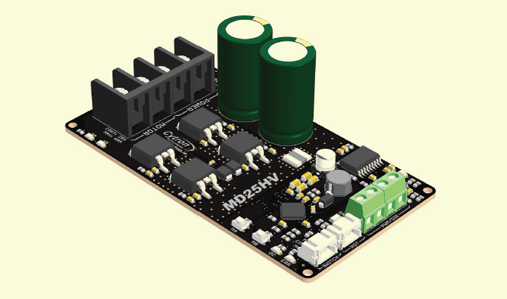
Strong and adaptable, the Cytron MD25HV 25Amp DC Motor Driver is made to manage brushed DC motors with a maximum continuous current of 25A and a maximum peak current of 70A. With a broad input voltage range of 10V to 45V, it is perfect for high-power uses including automation systems, robots, and electric cars. The MD25HV guarantees effective and dependable motor performance with features including bidirectional control, different control interfaces (PWM, analog, and RC), and integrated protective systems.
Description
The Cytron MD25HV 25Amp DC Motor Driver is a motor driver of superior quality that provides dependable and effective performance for applications involving high-powered DC motors. This device is equipped with sophisticated over-current protection and thermal shutdown capabilities, which guarantee a safe and dependable functioning even when subjected to heavy loads. Your direct current (DC) motors can be controlled in a manner that is both precise and responsive thanks to the driver's high PWM frequency and wide voltage range functionality.
BOARD LAYOUT & FUNCTION
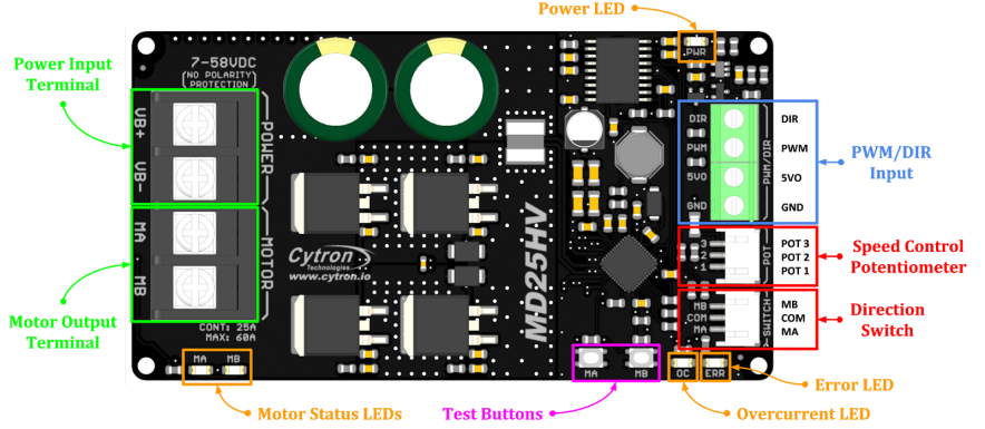
Table 1: MD25HV Board Functions
Function | Description |
Power InputTerminal | Connect to battery.
Warning : Connecting in reverse polarity will damage the motor driver instantaneously. |
Motor OutputTerminal | Connect to motor terminal. Motor direction is depending on the polarity. |
Power LED | Turn on when powerup. |
Error LED | Blink when there is error. |
OC (Overcurrent) LED | Turn on when currentlimiting is in action. Current limit threshold is depending on the boardtemperature. |
Motor StatusLEDs | Turn on when the motor is running.
|
Test Buttons | Press to test thefunctionality of themotor driver. Motor will run at 78% of full speed.
|
PWM/DIR Input | Control themotor with PWM/DIR signal.
|
Speed Control Potentiometer | Connect to 10KΩ potentiometer for motor speedcontrol.
|
Direction Switch | Connect to SPDT Switchfor motor direction control. MA and MB are internally pulled high.
|
* Actual motor direction depends on the motor connection. Swapping the connections (MA & MB) will reverse the direction.
SPECIFICATIONS
Table 2: MD25HV Absolute Maximum Ratings
No | Parameters | Min | Max | Unit |
1 | Power InputVoltage | 7 | 58 | V |
2 | Maximum MotorCurrent (Continuous) | - | 25 | A |
3 | Maximum MotorCurrent (Peak) | - | 60 | A |
4 | 5V Output Voltage | 4.9 | 5.1 | V |
5 | 5V Output Maximum Current | - | 250 | mA |
6 | Potentiometer AnalogInput Voltage (POT2) | 0 | 5 | V |
7 | Direction SwitchInput Voltage - Low Level(MA, MB) | 0 | 0.8 | V |
8 | Direction SwitchInput Voltage - High Level(MA, MB) | 3 | 5 | V |
9 | Logic InputVoltage - Low Level (PWM,DIR) | 0 | 0.8 | V |
10 | Logic InputVoltage - HighLevel (PWM, DIR) | 3 | 30 | V |
11 | PWM Input Frequency* | DC | 40 | KHz |
12 | Motor DriverOutput PWM Frequency (Output frequency is independent of input frequency) |
16 |
KHz | |
* Lock-Antiphase PWM is not supported.
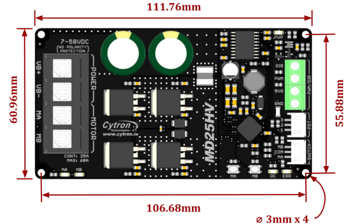
DIMENSION
Figure 2: MD25HV Dimension
INPUT MODE 1: PWM/DIR INPUT
Figure 3: PWM/DIR Input Connection Diagram
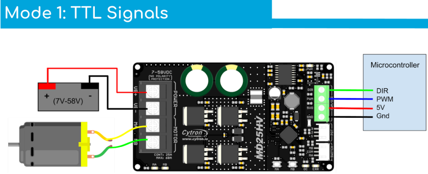
Table 3: PWM/DIR Input Truth Table
PWM | DIR | Output A (MA) | Output B (MB) | Motor |
Low | X (Don’t Care) | Low | Low | Brake |
High | Low | High | Low | Forward* |
High | High | Low | High | Backward* |
* Actual motor direction depends on the motor connection. Swapping the connections (MA & MB) will reverse the direction.
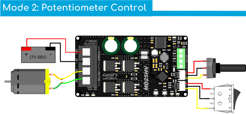
INPUT MODE 2: POTENTIOMETER/SWITCH INPUT
Figure 4: Potentiometer/Switch Input Connection Diagram
PROTECTION FEATURES
Overcurrent Protection with Active Current Limiting
When the motor tries to draw more current than what the motor driver can supply, the PWM to the motor will be chopped off and the motor current will be maintained at the maximum current limit. This prevents the motor driver from damage when the motor stalls or an oversized motor is hooked up. The OC LED will turn on when current limiting is in action.
Temperature Protection
The maximum current limiting threshold is determined by the board temperature. The higher the board temperature, the lower the current limiting threshold. This way, MD25HV is able to deliver its full potential depending on the actual condition without damaging the MOSFETs.
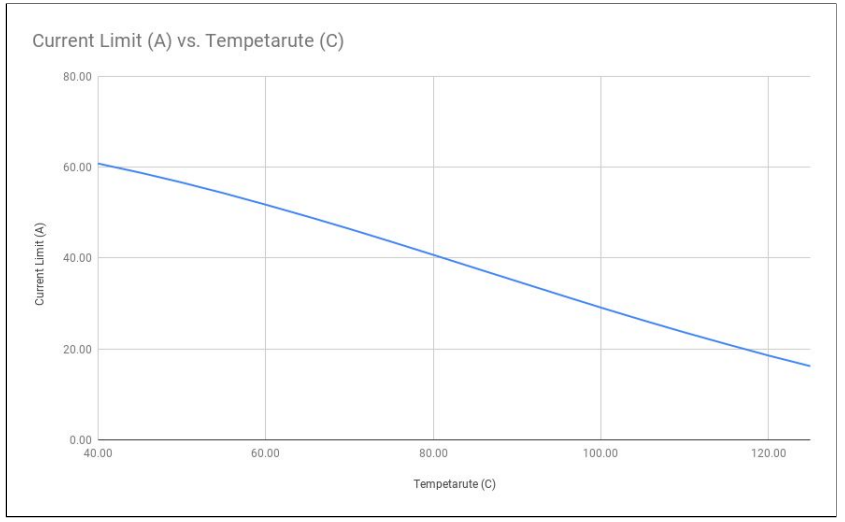
Figure 5: Maximum Current Limit vs Temperature Graph
(Visual representation not possible in text format. Please refer to the official Cytron documentation for the diagram.)
Undervoltage Shutdown
The motor driver output will shut down when the power input voltage drops below the lower limit. This is to make sure the MOSFETs have sufficient voltage to fully turn on and do not overheat. The ERR LED will turn on during undervoltage shutdown.
ERROR LED INDICATOR
Table 4: Error LED Indicator
ERR LED Blinking | DESCRIPTION |
2 | MOSFET Driver Error This happens when there is undervoltage erroror hardware failure. Please contact [email protected] for more details. |
3 | Overvoltage Error Power input voltage has exceeded the maximum rating. If switching power supply is being used, connect a motor shunt regulator or rechargeable battery with same voltage in parallel with the power supply.This is to absorb the regenerative energyfrom the motorduring deceleration. |
4 | Overheat Error Board temperature is over 80℃ (176℉). Thisis just servedas a warning. The motor driver can still be safely operated. |
Setup Guide
To set up the Cytron MD25HV 25Amp DC Motor Driver, follow these steps:
- Connect the driver to your power supply and DC motor, ensuring proper polarity.
- Connect the driver to your microcontroller or control board using the PWM and direction control pins.
- Power on the system and test the motor's operation using the control board or microcontroller.
- Adjust the PWM frequency and duty cycle to achieve the desired motor speed and torque.
Cytron Troubleshooting
- Motor Does Not Run
- Possible Causes
- No power supply or insufficient voltage.
- Incorrect wiring or loose connections.
- Faulty motor.
- PWM signal not present or incorrect.
- Solutions
- Check the power supply voltage to ensure it is within the 10V to 45V range.
- Verify all connections, ensuring they are secure and correctly wired as per the user manual.
- Test the motor independently to ensure it is functioning correctly.
- Ensure the PWM signal is being sent correctly and is within the supported frequency range (up to 20 kHz).
- Possible Causes
- Motor Runs in Wrong Direction
- Possible Causes
- Incorrect motor wiring (MA & MB connections swapped).
- Incorrect DIR signal.
- Solutions
- Swap the MA & MB motor connections.
- Verify that the DIR signal is correctly set for the desired direction.
- Possible Causes
- Overcurrent Protection Activated (OC LED On)
- Possible Causes
- Motor is drawing too much current (stall condition or oversized motor).
- Short circuit in motor wiring.
- Solutions:
- Check for mechanical obstructions or excessive load causing the motor to stall.
- Ensure the motor used is within the driver's current capacity.
- Inspect motor wiring for any short circuits or damage.
- Possible Causes
- Undervoltage Shutdown (ERR LED On)
- Possible Causes
- Power supply voltage is too low.
- Poor power supply connections.
- Solutions
- Ensure the power supply voltage is within the specified range (10V to 45V).
- Check and secure all power supply connections.
- Possible Causes
Pros & Cons
- Pros
- High continuous current rating
- Advanced over-current protection
- Wide voltage range
- Precise and responsive control
- Cons
- May be overkill for low-powered applications
- Can be susceptible to overheating under extreme loads
Customer Reviews
Customers have praised the Cytron MD25HV 25Amp DC Motor Driver for its high-powered performance and reliable operation. However, some have noted issues with overheating under extreme loads. Overall, the driver has received positive reviews and is recommended for high-powered DC motor applications.
Faqs
What is the continuous current rating of the Motor Driver?
What is the voltage rating of the Motor Driver?
Does the Cytron Motor Driver have over-current protection?
What is the PWM frequency of the Cytron?
Can the be used for low-powered applications?
How do I prevent overheating with the Cytron 25Amp?
What is the thermal shutdown feature of the Cytron?
Can the be used with AC motors?
What is the standby current of the Cytron?
How do I adjust the PWM frequency and duty cycle of the?
Leave a Comment