Ekwb Starter Liquid Cooling Kit Extreme360 User Guide
Content
Introduction
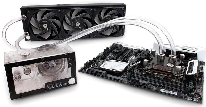
The Ekwb Starter Liquid Cooling Kit Extreme360 is a comprehensive solution designed for PC enthusiasts looking to enhance their system's cooling performance. This kit includes high-quality components such as a 360mm radiator, a powerful water pump, and an efficient CPU water block, ensuring optimal heat dissipation. With pre-assembled parts for easy installation, it caters to both beginners and experienced users. Priced at approximately $199, the Extreme360 offers an excellent balance of performance and value for liquid cooling systems.
Specifications
- 360mm Aluminum Radiator with 27 FPI
- High-Performance CPU Water Block (compatible with most modern CPUs)
- Pump-Reservoir Combo with Integrated Cable Management
- Three High-Static Pressure Fans (120mm each)
- Pre-assembled Tubing and Fittings for Easy Installation
- Compatible with Most Modern CPU Sockets and Motherboards
Safety precautions
- Keep and store the product away from the reach of children.
- Check the component list and condition of the product before installation. If there is any problem, contact the shop where you have purchased the problem to get a replacement or refund.
- EKWB d.o.o. is not responsible for any damages due to external causes, including but not limited to, improper use, problems with electrical power, ac-cident, neglect, alteration, repair, improper installation and improper testing.
- CPU and motherboard are subject to damage if the product is incorrectly installed.
- This product is a CPU liquid cooling solution kit, comprising of individual original EKWB parts. Combining this liquid cooling unit with parts, other than EK Water Blocks products, may lead to warranty loss.
- Product warranty period is 24 months.
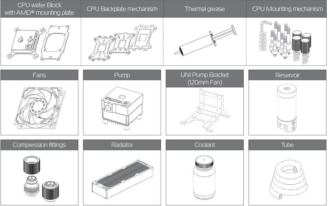
SCOPE OF DELIVERY

REQUIRED TOOLS

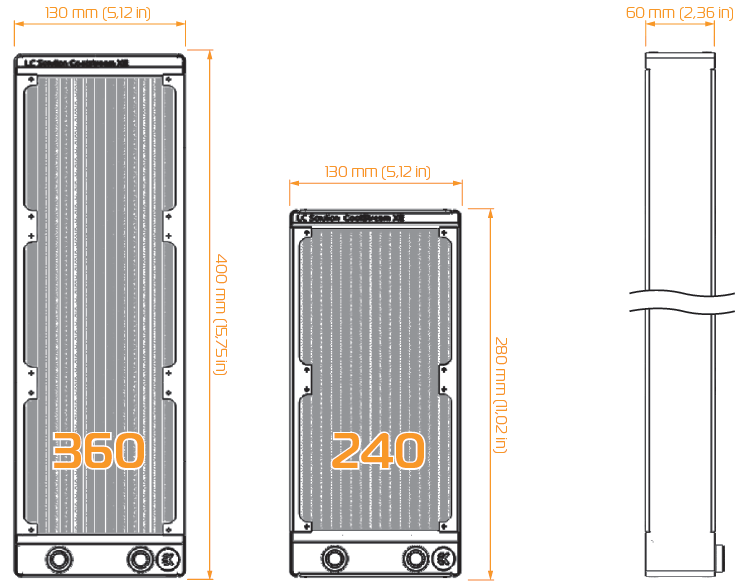
RADIATOR SPACE CONSTRAINT REQUIREMENTS
DOZEN GOOD ADVICES FOR THE NEWCOMERS
- In order to lower shipping costs we have decided to enclose only the coolant concentrate for liquid cooling. Therefor you need to provide 1 litre (1L) of distilled water. You can get it at every gas station or supermarket.
- Never run this system on tap water and always use the enclosed cooling concentrate in correct ratio.
- Never use alcohol, alcohol derivatives or alcohol based solvents in the system. Using alcohol might result in permanent damage to water cooling KIT components, especially acrylic parts of the system.
- Reservoir must be positioned above the height level of the water pump in order for liquid to fl ood the pump which is crucial for the fi rst start-up.
- Generally, for optimal performance, the Reservoir must be positioned be-fore the pump in the water loop.
- Generally, for optimal performance, the CPU water block should be right after the Radiator in the water loop.
- Generally, for optimal performance, the Pump should be positioned before the Radiator in the water loop.
- It is best practice to do a proper leak test before using your computer.
- If you spot any leaks, turn off the power immediately!
- Optimize tubing length in order to prevent excessive bending and kinking of the tubing.
- Never let your pump run dry. If this is happening for a prolonged period of time you may risk destroying water pump’s bearing, rendering the pump useless.
- You are encouraged to periodically clean the radiator assembly as it will collect dust over time. This is best done with soft wide tip brush and vacu-um cleaner. See chapter ‘General liquid cooling parts cleaning guide.’
WATER COOLING SYSTEM
GENERAL INFORMATION ON WATER BLOCK COMPATIBILITY
This CPU liquid cooling unit is pre-assembled for use with modern Intel desktop socket type motherboards. By default (out of the box) this water block supports the following CPU sockets:

- Intel Socket LGA-775
- Intel Socket LGA-115x
- Intel Socket LGA-1366
- Intel Socket LGA-2011(-3)
NOTE
This product is also fully compatible with AMD® AMx/FMx sockets but requires a user to replace factory installed Intel mounting plate with AMD® one. The following sockets are then compatible:
- AMD Socket AMx
- AMD Socket FMx
Narrow server type LGA-2011 is not supported by default – a Mounting plate Supremacy LGA-2011 Narrow ILM (EAN: 3830046990600) is mandatory to install this water block on narrow server type LGA-2011 motherboards. Replacing the mounting plate requires disassembly of the water block.
WHAT IS ENCLOSED
The following items are enclosed with each EK-Supremacy EVO water block:
- EK-Supremacy EVO universal CPU water block.
- PreciseMount EVO universal CPU mounting mechanism:
- M4 threaded thumb screws (4 pcs)
- LGA-2011 M4 threaded mounting studs (4 pcs)
- Springs (4 pcs)
- M4 threaded thumb nuts (4 pcs)
- Washers (4 pcs)
- AMD mounting plate
- EK-Supremacy Backplate
- Backplate rubber gasket
- Backplate for Intel LGA-1366 and AMD socket motherboards
- Backplate for Intel LGA-115x socket motherboards
- Allen (hex) key 2.5mm
- Additional Inserts and Jet plates:
- Jet J2 (0.3mm thick)
- Jet J3 (0.1mm thick)
- Insert I2
REPLACING THE JET PLATE
STEP 1
Please observe the table below to determine the optimal combination of insert and jet plate for your type of socket:Socket Optimal Insert Optimal Jet AMD®AMx / FMx I2 J2 LGA-775 I1 J2 LGA-115x I1 J2 LGA-1366 I1 J1 LGA-2011 I1 I1 LGA-2011(-3) I2 J3 STEP 2
Unscrew the four screws in counter-clockwise direction from the bottom of the water block using 2,5mm Allen key. Then you will be able to remove the plastic top and take the insert, inser pin and jet plate out.
When putting back together you will feel the jet plate lock into position on the insert when it is placed correctly.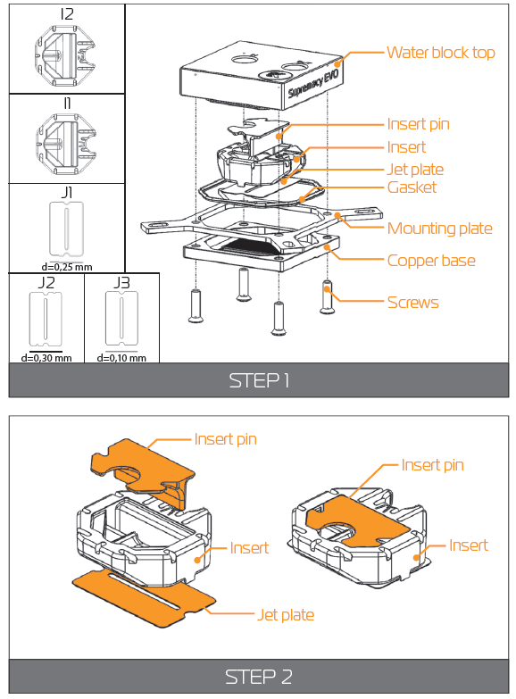
NOTE: STEP 2
- Unscrew the four screws in counter-clockwise direction from the bottom of the water block using 2,5mm Allen key. Then you will be able to remove the plastic top and take the insert, inser pin and jet plate out.
- When putting back together you will feel the jet plate lock into position on the insert when it is placed correctly.
- Screw the four screws back in but don’t exaggerate w STEP 2 ith the force applied.
Description
The Ekwb Starter Liquid Cooling Kit Extreme360 is engineered to provide superior cooling performance while maintaining a sleek and aesthetically pleasing design. The 360mm radiator is optimized for maximum heat dissipation, and the high-performance water block ensures efficient cooling of the CPU. The pump-reservoir combo is designed for quiet operation and comes with integrated cable management to keep your setup tidy.
The kit includes three high-static pressure fans that are optimized for radiators, ensuring maximum airflow and minimal noise. The pre-assembled tubing and fittings make installation straightforward, even for those new to liquid cooling.
INSTALLING THE WATER BLOCK
LGA-2011(-3) SOCKET MOTHERBOARDS
- STEP 1
Prepare the foil bag with mounting mechanism, which is enclosed with the CPU water block delivery.
Install four (4) specific LGA-2011 M4 thumb screws into four M4 threaded stubs on the LGA-2011 socket integrated latch mechanism (ILM). The screws are to be installed using no tools (i.e. pliers).
It is recommended to remove the motherboard form the PC chassis before proceeding with installation of the CPU water block because of the space constraint limitations of various computer cases. STEP 2
Cleaning the CPU: Wipe the CPU’s contact surface (by using non–abrasive cloth or Q-tip, as shown on sample photo).
Applying thermal compound: EK recommends blob or line method of applying the enclosed EK-TIM Ectotherm thermal compound to the CPU heat spreader (IHS) - see sample photo on right.
NOTICE
The quantity of about two rice grains is just about right. There is no need to cover the whole IHS. Applying too much thermal grease will have negative impact on the cooling performance!_socket_motherboards_ekwb_starter_liquid_cooling_kit_extreme360.png)
- STEP 3.:
Align the water block over the mounting screws on the LGA-2011(-3) motherboard with pre-installed CPU.
wARNING: Before proceeding with the installation It is mandatory to remove the protective foil from the backside of the water block.
Place an enclosed compression spring and thumb nut over each M4 thumb screw. Start fastening two thumb nuts at a time, preferably in cross pattern and do not tighten them fully until all of them are partially screwed in. Then - using your fingers only - screw in all four thumb nuts until you reach the end of the thread. STEP 4.:
Tighten the fitting barbs in clockwise direction until the gasket underneath is compressed.
The installation of the CPU water block is now complete.
WARNING: With EK-Supremacy EVO series water blocks it is mandatory to use the port that is nearest to the center of the water block as INLET port. Mixing the ports may result in less than ideal thermal perfor-mance of the water block._socket_motherboards_of_ekwb_starter_liquid_cooling_kit_extreme360.png)
LGA-115x SOCKET MOTHERBOARDS
- STEP 1
If already installed, please remove the motherboard from your computer and place it on an even surface with front facing down. - STEP 2
Preparing backplate rubber gasket
The enclosed rubber gasket is essential part of the backplate and mount-ing system and must be used every time you install this water block on your motherboard.
The rubber gasket has a partially cut inner part which needs to be removed when installed on Intel® LGA-115x motherboard. The rubber is held on four places and can be peeled away with hand. - STEP 3
Install backplate rubber gasket and place metal backplate for Intel® LGA-115x socket to the back of your motherboard RIBBED SIDE UP! (facing away from the motherboard) Align the holes on the motherboard with holes on rubber gasket and backplate.
WARNING: Make sure to orientate the rubber gasket to fit past the CPU socket ILM backplate. On certain ITX form factor motherboards the rubber gasket may need to be trimmed using household scissors.
Carefully rotate motherboard assembly with front side facing up with one hand while holding the backplate and rubber in place with the other hand. STEP 4
Install four (4) M4 thumb screws onto your motherboard. It is mandatory to put 0.7mm plastic washer underneath each of the M4 thumb screws. Tighten the screws to the metal backplate until you reach the end of the thread. Using tools (such as pliers) is not recommended.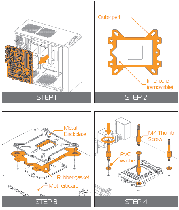
- STEP 5
Cleaning the CPU: Wipe the CPU’s contact surface (by using non–abrasive cloth or Q-tip, as shown on sample photo).
Applying thermal compound: EK recommends blob or line method of applying the enclosed EK-TIM Ectotherm thermal compound to the CPU heat spreader (IHS) - see sample photo on right.
WARNING: The quantity of about two rice grains is just about right. There is no need to cover the whole IHS. Applying too much thermal grease will have negative impact on the cooling performance! - STEP 6
Align the water block over the mounting screws on the LGA-115x motherboard with pre-installed CPU.
NOTICE: Before proceeding with the installation It is mandatory to remove the pro-tective foil from the backside of the water block.
Place an enclosed coiled spring and thumb nut over each M4 thumb screw. Start fas-tening two thumb nuts at a time, preferably in cross pattern and do not tighten them fully until all of them are partially screwed in. Then – using your fingers only screw in all four thumb nuts until you reach the end of the thread. - STEP 7
WARNING: With EK-Supremacy EVO series water blocks it is mandatory to use the port that is nearest to the center of the water block as INLET port. Mixing the ports may result in poor thermal performance of the water block.
Tighten the fitting barbs in clockwise direction until the gasket underneath is com-pressed. STEP 8
Install the CPU water block along with the motherboard back into the computer chassis.
The installation of the CPU water block is now complete.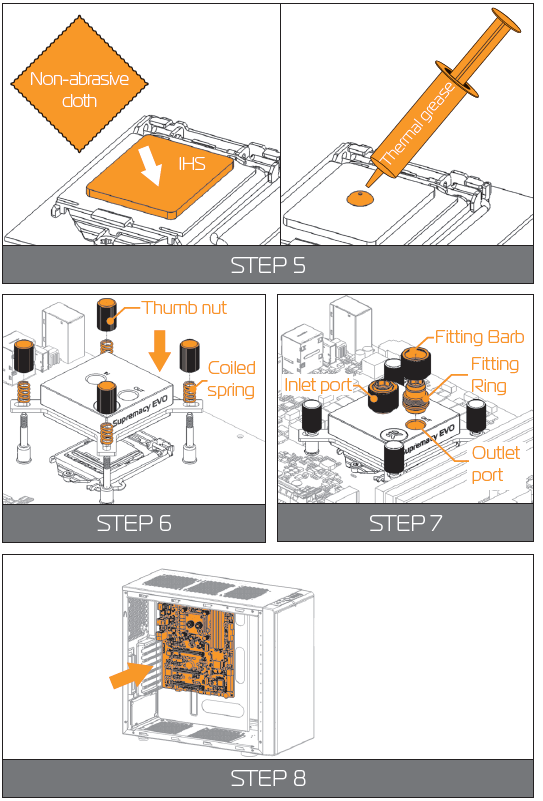
AMD SOCKET MOTHERBOARDS
- STEP 1
Replacing the mounting plate:
Place the water block on a neven surface and remove the four M4x16 DIN 7991 screws attaching the copper base to the top using 2,5mm Allen key in counter-clockwise direction. - STEP 2
Replace the Intel® factory installed mounting plate with AMD® one. You will feel the mounting plate locking into the position when placed correctly on to the top.
Reseat the O-ring gasket (57x2 mm) into the gap between the mounting plate and water block top.
WARNING: Reinstall the M4x16 screws and tighten them using 2,5mm Al-len key to screw them in clockwise direction. STEP 3
If already installed, please remove the motherboard from your computer and place it on an even surface with front facing up.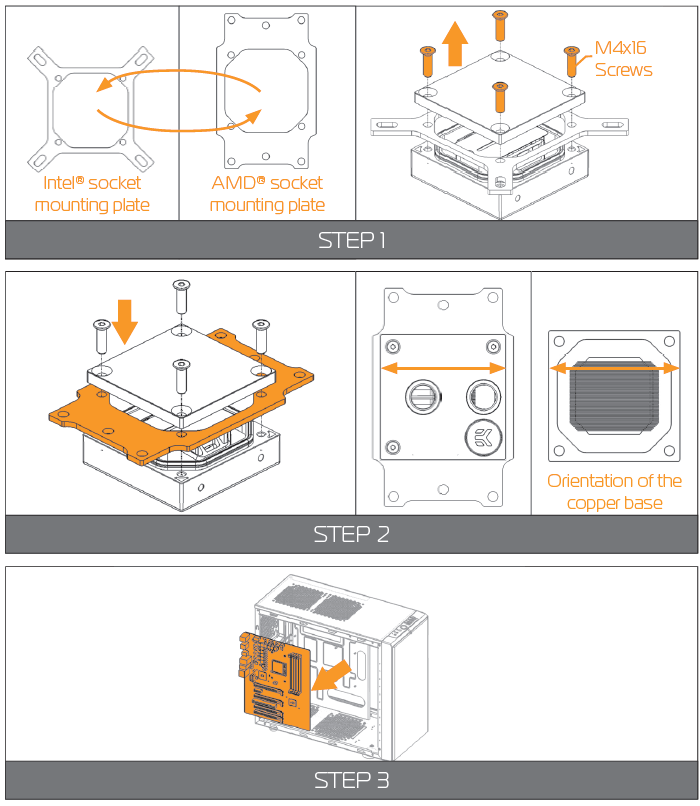
- STEP 4
Removing of the original plastic hold-down clamps and the factory backplate:
Using Philips-head screwdriver remove the four UNC 6-32 screws securing the original plastic hold-down clamps around the socket as shown on the sketch. Remove the original AMD® backplate and the hold-down clamps and store them away. See sketch for further part identification. - STEP 5
Preparing backplate rubber gasket
The enclosed rubber gasket is essential part of the backplate and mounting system and must be used every time you install this water block on your moth-erboard.
WARNING: With AMD® Sockets you should use whole rubber backplate including the inner core. STEP 6
Install backplate rubber gasket and place metal back-plate for AMD® socket to the back of your mother-board RIBBED SIDE UP! (facing away from the moth-erboard) Align the holes on the motherboard with holes on rubber gasket and backplate.
Carefully rotate motherboard assembly with front side facing up with one hand while holding the backplate and rubber in place with the other hand.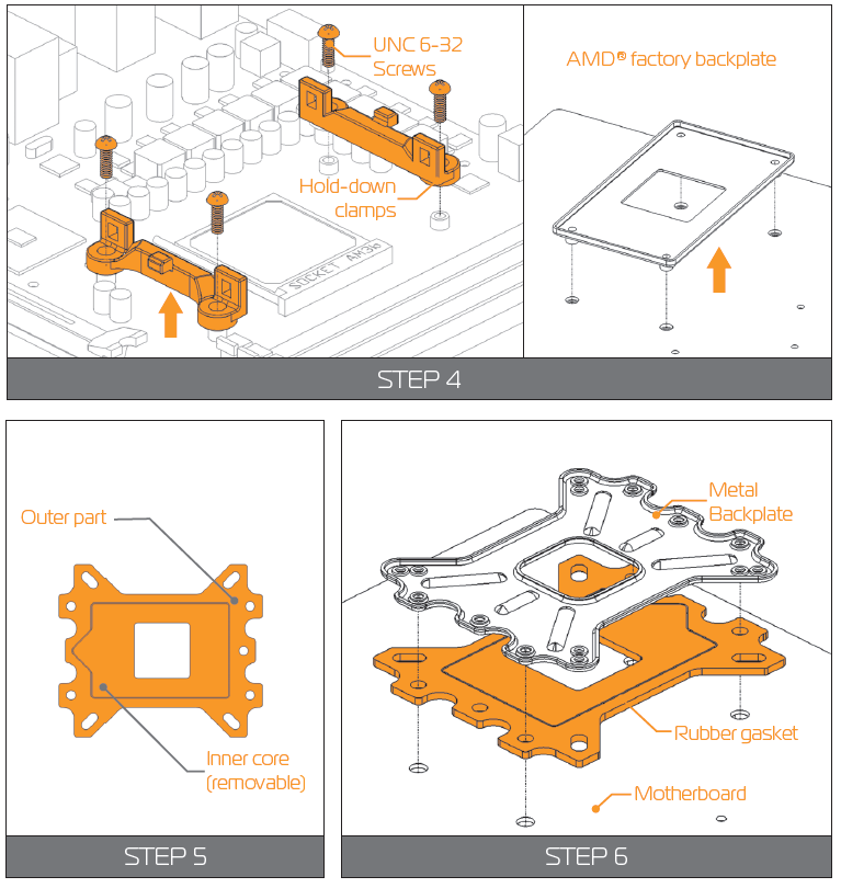
- STEP 7
Prepare the foil bag with mounting mechanism, which is enclosed with the CPU water block delivery.
Install four (4) M4 thumb screws onto your motherboard. It is mandatory to put 0.7mm plastic washer underneath each of the M4 thumb screws. Tighten the screws to the metal backplate until you reach the end of the thread. Using tools (such as pli-ers) is not recommended. - STEP 8
Cleaning the CPU: Wipe the CPU’s contact surface (by using non–abrasive cloth or Q-tip, as shown on sample photo).
Applying thermal compound: EK recommends blob or line method of applying the enclosed EK-TIM Ectotherm thermal compound to the CPU heat spreader (IHS) - see sample photo on right.
NOTICE: The quantity of about two rice grains is just about right. There is no need to cover the whole IHS. Applying too much thermal grease will have negative impact on the cooling performance! STEP 9
Align the water block over the mounting screws on the AMD® socket motherboard with pre-installed CPU.
WARNING: Before proceeding with the installation It is mandatory to remove the pro-tective foil from the backside of the water block.
Place an enclosed coiled spring and thumb nut over each M4 thumb screw. Start fas-tening two thumb nuts at a time, preferably in cross pattern and do not tighten them fully until all of them are partially screwed in.
Then – using your fingers only screw in all four thumb nuts until you reach the end of the thread.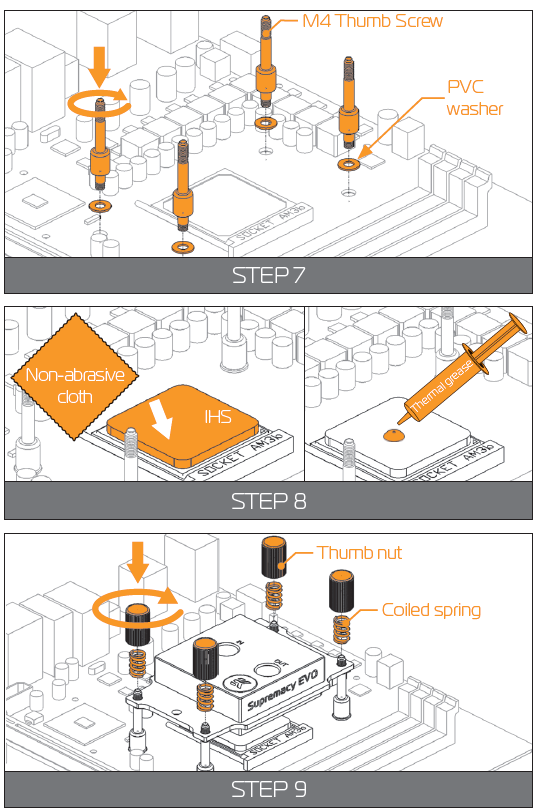
- STEP 9
WARNING: With EK-Supremacy EVO series water blocks it is mandatory to use the port that is nearest to the center of the water block as INLET port. Mixing the ports may result in poor thermal performance of the water block.
Tighten the fitting barbs in clockwise direction until the gasket underneath is compressed. STEP 10
Install the CPU water block along with the motherboard back into the computer chassis.
The installation of the CPU waterblock is now complete.
INSTALLING THE RADIATOR AND FANS
OPTION #1:
INSTALLING THE RADIATOR AND FANS
- STEP 1
Install the fans on the radiator. - WARNING: Ideally, the radiator should either:
- A) receive the coldest air possible (by placing the radiator on the air inlet) or
- B) serve as an overall hot air exhaust (by placing the radiator on the exhaust).
The latter results in overal decrease of temperature throughout the entire computer chassis but also leads to slightly higher liquid tem-peratures. A reversed air flow is viable option but one should always strive to achieve unidirectional flow of air throughout the chassis.
Take the four UNC 6-32x30mm screws for each fan and screw them in. Use enclosed Allen key to tighten the screws in clockwise direction.
- STEP 2
Prepare your suitably-sized PC chassis for installation of radiator unit. The position of the unit in the chassis depends on the size, fan mounting holes and the hardware you have installed. You must make sure that the unit fits into the chassis. Usually the chassis have standard fan mounting holes pre-drilled so you should look for holes with spacing of 105mm. (A standard computer cooling 120mm fan) STEP 3
Align the holes on the radiator with the ones on the PC chassis.
Take the four UNC 6-32x5mm screws for each fan and guide them through the holes on the chassis to screw them into the threaded holes on the radia-tor. Tighten them in clockwise direction using Allen key.
STEP 4
Install the compression fittings on both to both G1/4 extender openings on the radiator. Tighten the fitting barbs in clockwise direction until the gasket underneath is compressed.
The installation of the radiator- and radiator cooling fans is now complete.
OPTION #2:
INSTALLING THE RADIATOR AND FANS IN ONE GO
- STEP 1.:
Prepare your suitably-sized PC chassis for installation of radiator unit. The position of the unit in the chassis depends on the size, fan mounting holes and the hardware you have installed. You must make sure that the unit fits into the chassis. Usually the chassis have standard fan mounting holes pre-drilled so you should look for holes with spacing of 105mm. (A standard computer cooling 120mm fan) - STEP 2.:
Align the holes on the fans and the radiator with the ones on the PC chassis.
NOTICE: Ideally, the radiator should either:- A) receive the coldest air possible (by placing the radiator on the air inlet) or
- B) serve as an overall hot air exhaust (by placing the radiator on the exhaust). The latter results in overal decrease of temperature throughout the entire computer chassis but also leads to slightly higher liquid temperatures. A re-versed air flow is viable option but one should always strive to achieve unidi-rectional flow of air throughout the chassis.
Take the four UNC 6-32x30mm screws for each fan and guide them through the holes on the chassis and fans to screw them into the threaded holes on the radiator. Tighten them in clockwise direction using enclosed Allen key.
STEP 3.:
Install the compression fitting on both to both G1/4 extender openings on the radiator. Tighten the fitting barbs in clockwise direction until the gasket underneath is compressed.
The installation of the radiator- and radiator cooling fans is now complete.
INSTALLING THE PUMP UNIT
OPTION 1:
INSTALLING THE PUMP ON THE CHASSIS BOTTOM
- STEP 1
The KIT comes with pump unit with pre-installed anti-vibration decouplers.
Take the unit and place it on the EK-UNI Pump Bracket (120mm Fan) Verti-cal, as shown on the picture.
WARNING: Turn your pump in any direction, as long it is not turned upside-down.
Secure it from the bottom side using four M4x4 screws and PVC washers. Tighten them in clockwise direction using enclosed 2,5mm Allen key.
NOTICE: This unit can be installed anywhere where there is a 50x50mm square mounting hole pattern on the chassis without using any pump bracket. STEP 2
The position of the unit in the chassis depends on the fan mounting holes and the hardware you have installed. Usually the chassis have Pre-drilled standard fan mounting holes on the bottom one you should look for holes with spacing of 105mm. (A standard computer cooling 120mm fan).
NOTICE: Alternatively you can drill four Ø4,5mm holes using electric pow-er drill to the most suitable place on the bottom of your computer chassis.
Put four M4x6 DIN7984 screws through the holes on the UNI pump bracket from the upper side.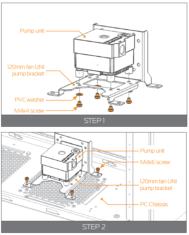
- STEP 3
Secure the M4x6 screws (from the previous step) with four M4 nuts and PVC washers. Tighten them using 2,5mm Allen key with the screws.
WARNING: Make sure that the screws are holding tight but do not exaggerate with the force applied. STEP 4
WARNING: This unit can be installed anywhere where there is a 50x50mm square mounting hole pattern on the chassis without using any pump bracket.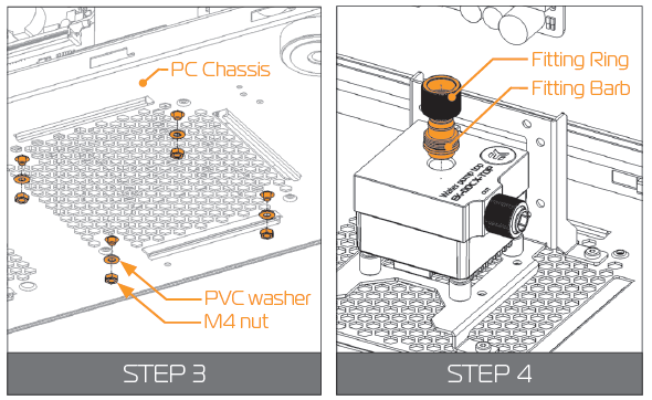
Tighten the fi tting barbs in clockwise direction until the gasket underneath is compressed.
The installation of the pump unit is now complete.
OPTION 2:
INSTALLING THE PUMP ON THE CHAS-SIS WALL
STEP 1
The KIT comes with pump unit with pre-installed anti-vibration decouplers.
Take the unit and place it on the EK-UNI Pump Bracket (120mm Fan) Vertical, as shown on the picture.
WARNING: Turn your pump in any direction, as long it is not turned upside-down.
Secure it from the bottom side using four M4x4 screws and PVC washers. Tighten them in clockwise direction using enclosed 2,5mm Allen key.
NOTICE: This unit can be installed anywhere where there is 50x50mm square mounting hole pattern of the chassis.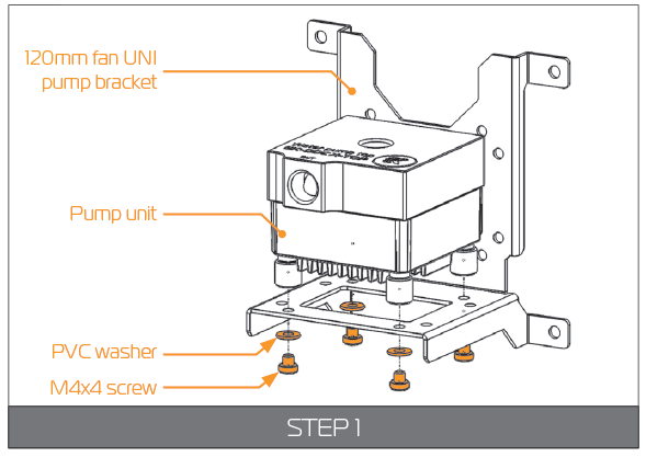
- STEP 2
The position of the unit in the chassis depends on the fan mount-ing holes and the hardware you have installed. Usually the chassis have Pre-drilled standard fan mounting holes on the sides one you should look for holes with spacing of 105mm. (A standard computer cooling 120mm fan).
NOTICE: Alternatively you can drill four Ø4,5mm holes using electric power drill to the most suitable place on the wall of your computer chassis.
Put four M4x6 DIN7984 screws through the holes on the UNI pump bracket from the front side.
STEP 3
Secure the M4x6 screws from the previous step with four M4 nuts and PVC washers. Tighten them using 2,5mm Allen key with the screws.
WARNING: Make sure that the screws are holding tight but do not exaggerate with the force applied. STEP 4
WARNING: The pump unit has clearly marked Outlet (OUT) around the G1/4 port. Not taking that into account will lead to reverse fl ow.
Tighten the fi tting barbs in clockwise direction until the gasket un-derneath is compressed.
The installation of the pump unit is now complete.
INSTALLING THE RESERVOIR
- STEP 1
WARNING: The Kit X comes with Reservoir EK-RES X3 150 which has en-closed mounting clamps.
NOTICE: Your reservoirs outlet port, which is usually directed to-wards the pumps inlet port should be installed in same level or higher than the pump in order to allow easy priming.
You can turn your reservoir in any direction as long as the outlet port is always fl ooded. - STEP 2
Look for the suitable position in your PC chassis. The two clamps must hold the reservoir tube so be careful that you install them from 15mm to 60mm apart as shown on the picture on the right.
NOTICE: Alternatively you can drill two Ø4,5mm holes using electric power drill to the most suitable place on the wall of your computer chassis.
Take the two M4x12 screws and guide them through the central clamp holes and the holes on the chassis. STEP 3
Secure the M4x12 screws from the previous step with two M4 nuts and PVC washers. Tighten them using Phillips screwdriver with the screws.
WARNING: Make sure that the screws are holding tight but do not exaggerate with the force applied.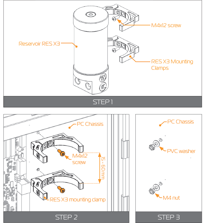
- STEP 4
Push the reservoir against the clamps. It should smoothly slide and lock into them.
These holders allow rotating the reservoir or sliding it up and down a bit – depends on the distance be-tween the clamps. - STEP 5
Fix the position of the reservoir by tightening the ad-justment screw on each clamp.
Use enclosed 2,5mm Allen key. STEP 6
NOTICE: The reservoir has multiple G1/4 ports, which can be used as inlet or outlet port. Please choose the inlet or outlet port de-pending on your loop configuration and space constraints.
Tighten the fitting barbs in clockwise direction until the gasket underneath is compressed.
The installation of the reservoir is now complete.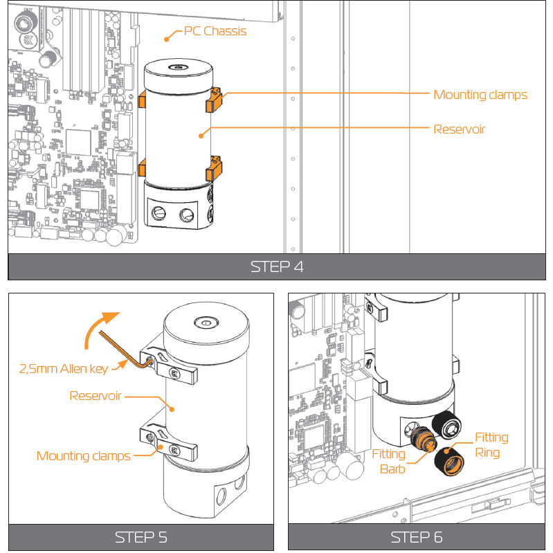
CONNECTING THE TUBING
WARNING: If you are expanding your loop with additional liquid cooling components please proceed to Page 31, chapter POSSIBILITIES OF EXPANDING THE SYSTEM.
- STEP 1
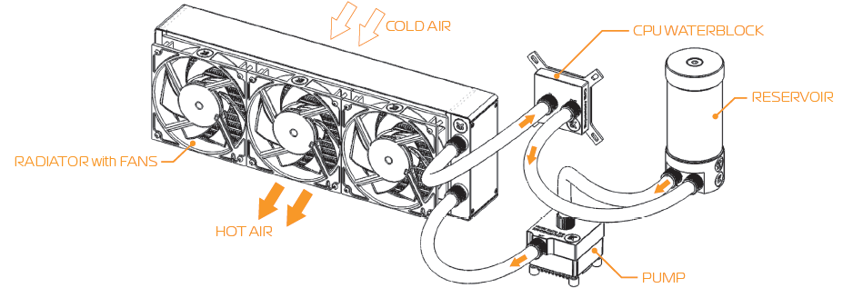
In order to successfully route the tubing it is recommended that you check the water cooling scheme on the right picture.
It is best that the water block receives the coldest fl uid as pos-sible, therefore you should connect the radiator’s outlet port with the water block’s inlet port. This is best practice but it is not mandatory. STEP 2
Visualize the tube’s routes and then measure the distance by trying to fi t it into the chassis. Mark the required length with a marker. Before cutting it is recommended that you leave an additional 2 or 3 centimeters to spare. You can shorten it af-terwards.
NOTICE: Please make sure that the tube is not bent or twisted. This way the coolant will be able to fl ow without restriction.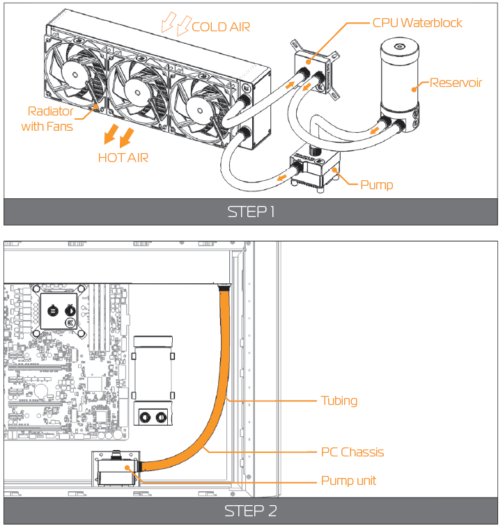
- STEP 3
WARNING: If you have assembled the components according to this installation manual you should have all the compression fittings installed.
In order to install the tubing onto the compression fittings you will have to remove the fitting ring by screwing it in counter-clockwise direction. - STEP 4
Slide the fitting ring along the tube with the threaded side fac-ing the fitting barb.
Install the tube on fitting barb. If needed heat the tube in warm water (40-50°C). You can do that by forcing it to slide over the edge as far as it goes. STEP 5.:
Slide the fitting ring towards the barb and tighten it in clock-wise direction as far as it goes.
Repeat the procedure on all the fittings in order to connect the water cooling loop.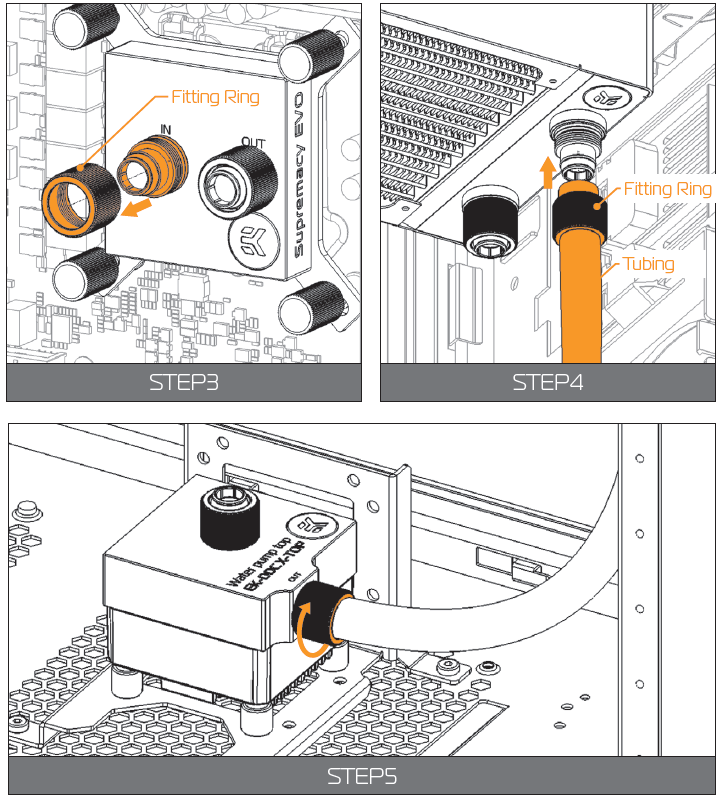
ELECTRICAL CONNECTIONS
CONNECTING THE PUMP UNIT
STEP 1
Connect the 4-pin Molex male connector to the male Molex connector of the power supply.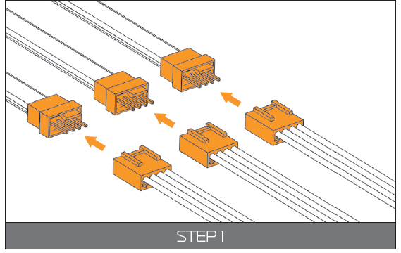
STEP 2
Take the 4-pin female connector and plug it to the male connector header located on the motherboard. Always use CPU-dedicated fan headers if possible.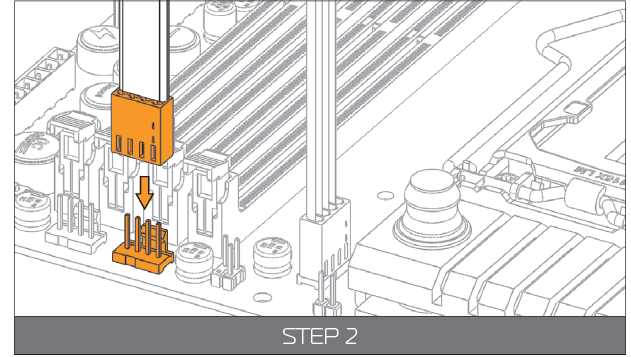
NOTICE: Always use CPU fan header. On majority of motherboards these head-ers usually offer best PWM regulation.
CONNECTING THE FANS
- STEP 1
To connect the fans you might need EK-Cable Y splitter.
The EK-Cable Y splitter is enclosed with the KIT delivery.
NOTICE: Connect the female connectors from the fans with male connectors on the fan splitter cable. STEP 2
Connect the female EK-Cable Y splitter connector to the male connec-tor header located on the motherboard. Always use CPU-dedicated fan headers if possible.
NOTICE: Always use CPU fan header. On majority of motherboards these headers usually offer best PWM regulation.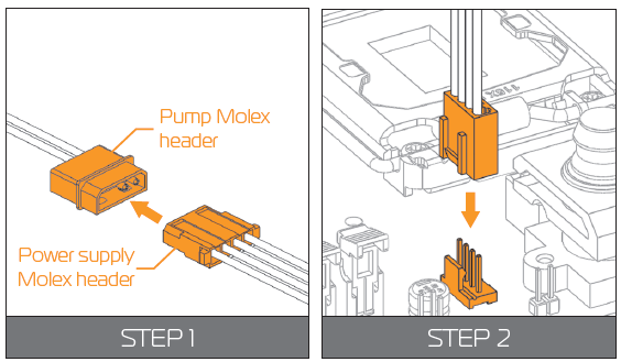
RECOMMENDED FILLING AND LEAK-TESTING PROCEDURE
- STEP 1
It is mandatory to do the following:- Disconnect all PSU power connectors (4/8-pin ESP, 24-pin ATX, PCI-express power, SATA power) in your computer.
Plug the EK-ATX Bridging plug (enclosed) to your 24-pin ATX PSU ca-ble which allows jump starting your computer.
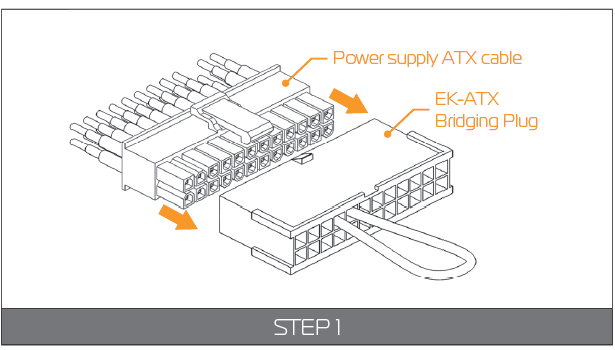
This procedure requires only the pump to be connected to the power supply (PSU). Everything else needs to be disconnected!
WARNING: This steps must be done to prepare the power supply for the pump in order to fi ll the water cooling loop with coolant and run a leak test.
Your system is now ready to be charged for the fi rst time.
FILLING THE SYSTEM FOR THE FIRST TIME
- STEP 1: Preparing the cooling liquid.
The coolant comes in concentrated form. In order to prepare the cooling liquid you must take a 100mL clear coolant concentrate, which is enclosed with the kit, and mix it with 900mL of distilled water.
Make sure you mix the mixture properly before pouring it into the water cooling loop.
WARNING: Store the remaining liquid into a PET bottle. Do not use any food or beverage container! - STEP 2
Remove the top cover of your reservoir by unscrewing it in counter-clock-wise direction.
NOTICE: It is recommended to protect the exposed hardware with a few paper towels in order you have a leak or mistakenly spill the cool-ant when pouring it.
Take the pre-mixed coolant and pour it into the reservoir until the coolant level is about 2 centimeters below the top. STEP 3
WARNING: Please check again if you have plugged in the EK-ATX Bridging plug and EK-Cable Pump Testing Adapter correctly. Refer to page 27, chapter RECOMMENDED FILLING AND LEAK-TESTING PROCEDURE.
Turn the power supply on briefl y and check that only the pump is running.
- STEP 4
When you turn on the power supply the coolant should be pushed from the reservoir to other water cooling components, therefore you have to fill the coolant continuously while the pump is running.
NOTICE: Alternatively you can cycle (turn on and of) the power supply in few second intervals to speed up the air bleeding process.
When the coolant level becomes steady fill the reservoir so that the coolant level is about 2 centimeters below the edge. Screw the reservoir top back in clockwise direction. - STEP 5
Shake and tilt the PC chassis to remove any air possibly trapped in the radia-tor. You may need to add more coolant. STEP 6: 24 HOUR LEAK TEST
WARNING: It is best practice to run your pump for at least 24 hours in order to ensure the system is leak free. Once the 24 hour leak test has been completed and there is no sign of leaking fluid you are free to finish your computer build.
You will not be needing the ATX Bridging Plug cable anymore. Connect all the necesary cables to the motherboard, graphics card and expansion drives.
DRAINING OF THE LOOP
- STEP 1
WARNING: Before disassembling the water cooling loop it is mandatory turn off your computer and pull the power cord from the socket. Prepare some paper towels and stack them over the hardware.
Take a container and put it under the reservoir unit.
NOTICE: You can alternatively pull the reservoir off the clamps and outside the chassis if you don’t have enough space to put a container inside the chassis. - STEP 2
Unscrew the fitting ring on one port on the reservoir. Rotate the ring in counter-clockwise direction.
Gently pull the tube off the fitting and direct it into the container.
Let the coolant flow into the container. STEP 3
Disconnect the other tube - connected to the reservoir second port.
Keep the first tube directed in the container and blow into the other tube to additionally drain the system.
In order to throughly drain the system you can tilt the chassis in multiple direc-tions. Alternatively you can detach the reservoir from the clamps and pour the residual coolant out.
NOTICE: Keep the disconnected tube ends over the paper towel to prevent the coolant spillage. You can additionally dry the tubes and the res-ervoir to keep the hardware safe.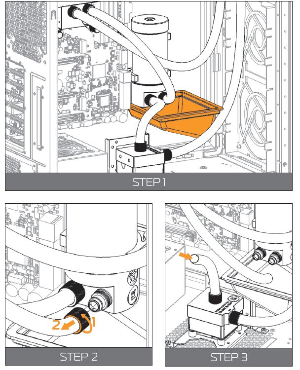
POSSIBILITIES OF EXPANDING THE SYSTEM
The best part of custom water cooling loop is that the system can be extended and the cooling capacity can be extended almost without limitations.
WARNING: Rule of thumb is to use at least one 120mm radiator (section) per each water cooled component plus one ‘spare’.
For example, if one is liquid cooling a CPU and a single high-performance graphics card it is recommended at least one 240mm (2x 120mm) radiator for good performance. Ideally, one would get a 360mm (3x 120mm) radiator for best performance. Motherboard- and memory water blocks usually have lower power output therefore they are not included in this equation.
In this manual we will expand the loop with an additional GPU full cover water block. You can also expand the loop with an additional radiator, reservoir, motherboard block.
STEP 1
WARNING: If already filled, drain the water cooling loop according to the instructions in the chapter DRAINING OF THE LOOP.
Install the unit, with which you are expanding the system according to its installation manual. When positioning it in the loop take notice that water blocks must receive the coldest coolant as possible.
Carefully determine the optimal tube routing and install the compat-ible fittings (10/13mm) and optionally the plugs.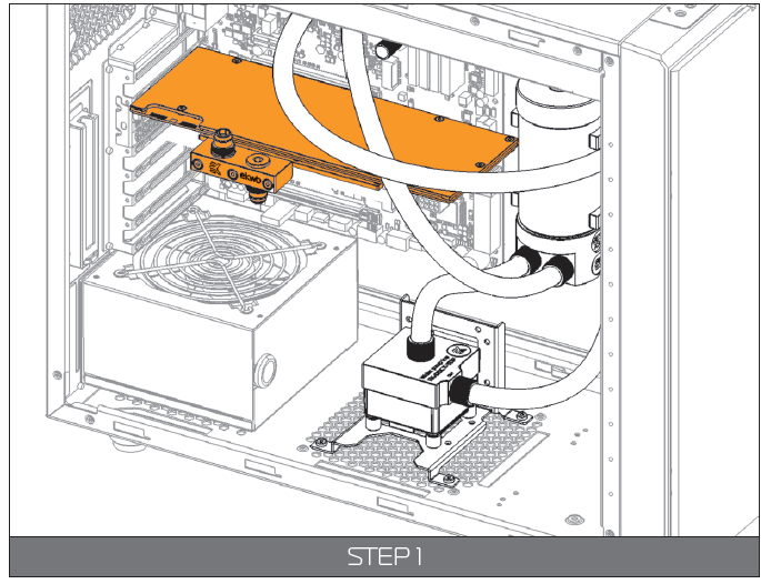
STEP 2
Measure the length of the tube that is needed to connect the CPU to GPU water block and the GPU water block to the reservoir. You can use a pair of scissors or a knife to cut the tube.
NOTICE: You may need additional tubing to connect the water block.
Attach the tube onto the both fitting barbs until it sits firmly. Secure the fitting compression ring to make the assembly complete. Check again that all of the tubing is secured by compression fittings as intended. If it is not, please repeat STEP 1 to STEP 5 of chapter CONNECTING THE TUBING.
Fill the system by following the steps in the chapter FILLING THE SYSTEM FOR THE FIRST TIME.
Setup Guide
To set up the Ekwb Starter Liquid Cooling Kit Extreme360,
- Start by preparing your workspace and ensuring all components are included.
- Mount the radiator to your case, typically at the top or front panel.
- Next, install the CPU water block according to the provided instructions, ensuring proper thermal paste application and secure mounting.
- Connect the tubing from the radiator to the water block and pump-reservoir combo.
- Securely mount the pump-reservoir combo to your case and connect it to your power supply and motherboard.
- Finally, connect the fans to your radiator and configure them in your motherboard settings or using a fan controller.
Cooling Kit Extreme360 MAINTENANCE
In order to obtain the best performance through whole lifespan of the product it is crucial to follow these maintenance tips:
- TIP 1: DUST REMOVAL
It is mandatory to remove the dust every 2-3 months. EK recommends to use a vacuum cleaner or compressed air to blow the dust away. The most dusty is usually the radiator so pay special attention to that. Do not forget to turn off the computer and unplug the power supply. It is recommended to remove the dust outside. - TIP 2: CHECKING ELECTRICAL COMPONENTS
Once a year you should check the pump and the fans, if they are running as they should. The pump and fans must run silently without any rattling noises and must react to PWM duty cycle changes. All imperfections may lead to overheating and breakdown. - TIP 3: CLEANING THE UNIT (RELATED TO CHAPTER TROUBLESHOOTING)
Every year the unit should be thoroughly cleaned. You must let all the cool-ant out (Page 30). The radiator must be flushed and the pump checked and cleaned. It is recommended to change the tubing. - TIP 4: USE EK DESIGNED AND MANUFACTURED PARTS ONLY
It is recommended to use only genuine EK Water Blocks liquid cooling gear, parts and add-ons to prevent any performance, compatibility and warranty issues.
TROUBLESHOOTING
IN CASE OF CPU OVERHEATING
Very high CPU temperatures are usually the symptoms of malfunctioning liquid cooling loop, assuming the contact between CPU heat spreader and water block itself is good and that the water itself is adequately cooled within the radiator. This can occur either due to:
- Malfunctioning or non-working water pump: The symptoms usually include rapid spike in temperature when stressing your CPU to the maxi-mum (for example with Prime95 software). Make sure the pump is plugged in to the power connector and that the liquid is indeed flowing in your sys-tem. You should feel the pump vibrating in your hand. Observe the flow indicator or flow meter reading if present.
- Malfunctioning or non-working cooling fans: The symptoms usu-ally include rapid spike in temperature when stressing your CPU to the maximum. Make sure the cooling fans are plugged in to the power con-nector hub and that the blades are indeed rotating.
- Kink in the liquid cooling tubing: Very similar symptoms to both above described. Thin-walled tubing may collapse easily under low radius turns or when obstructed by other computer chassis elements such as closing side panel doors. Check the tubing for any signs of kink which restrict the flow. This is normally not the case when using original tubing.
- Clogged microchannels in the water block: Microchannels can get clogged easily with various dirt particles and impurities, especially with plas-ticizer powder which has leached from the tubing (When using unsafe liquid cooling tubing). The symptoms usually include rapid spike in temperature when stressing your CPU to the maximum, flow rates are very low. Visually inspect the water block internals for any buildup or contamination and clean the system if necessary. In case the water block with translucent acrylic top is employed this inspection can be done without disassembling the system.
- Thermal interface material (paste/grease) not applied or applied improperly: Lack of - or even too much TIM - may result in CPU over-heating. Please refer to STEP 2 in Installing the water block section.
Another culprit could be partially or completely defective CPU. Some CPUs run at higher temperatures than the others.
Overheating of the CPU can also occur due to:
- Poor thermal contact within the CPU itself: Some CPUs, such as Intel LGA-1151 socket based Skylake, Intel LGA-1150 based Haswell and older, socket LGA-1155 based Ivy Bridge are notorious for their poor ther-mal contact between the CPU die and the heat spreader (IHS) itself due to the use of poor TIM. This is the problem of the processor and not the CPU liquid cooling unit. These CPUs are known to run very hot (80°C+) even on factory set frequencies. For best performance it is usually recommended to replace the TIM between the die and the IHS or to even run the processor de-lidded. Both require hazardous IHS removal which voids processor’s warranty but can lead to temperature decrease of 30°C and higher.
NOTICE: Upon exhausting all options please consult EK knowledge base at http://support.ekwb.com . Raise a question through EK Support ticketing system if needed.
THE COOLER IS TOO LOUD
This kit is equipped with fast-spinning EK-Vardar high-static pressure PWM controlled fans, which run at high speed if the UEFI/BIOS is not set to con-trol fan speed. Make sure to set control mode to PWM (instead of DC)! On majority of motherboards this feature can be found in ‘Hardware Monitoring’ section of the UEFI/BIOS. Please consult your motherboard manual on how change fan speed.
General ASUS Z170/X99 motherboard guide:
- Enter UEFI and go to QFAN Control
- Select the FAN header you wish to edit (the one that you have con-nected the pump- or fan to)
- Select PWM mode (instead of DC)
General ASRock Z170/X99 motherboard guide:
- Enter UEFI and go to H/W Monitor
- Choose the FAN header you wish to edit (the one that you have con-nected the pump- or fan to)
- Change from ‘Full Speed’ to ‘Silent’, ‘Standard’ or ‘Performance’ mode
General Gigabyte Z170/X99 motherboard guide:
- Enter UEFI and go to M.I.T. - > PC Health Status
- Select (CPU Fan) Speed Control optionbox and select ‘Auto’, ‘Normal’ or ‘Manual’.
General MSI Z170/X99 motherboard guide:
- Enter UEFI and go to Hardware Monitor
- Select the FAN header you wish to edit (the one that you have con-nected the pump- or fan to)
- Enable Smart Fan Mode Checkbox
- Change ramp-up curve by dragging and dropping 4 coloured squares
Pros & Cons
Pros:
- High-performance cooling for CPUs
- Ease of installation with pre-assembled tubing and fittings
- Quiet operation of pump and fans
- Aesthetically pleasing design
- Compatible with most modern CPU sockets and motherboards
Cons:
- Higher cost compared to air cooling solutions
- Potential for air leaks if not installed correctly
- Requires periodic maintenance (coolant checks, cleaning)
- Limited expandability without additional components
Customer Reviews
Customers have praised the Ekwb Starter Liquid Cooling Kit Extreme360 for its ease of installation and impressive cooling performance. Many have noted that it significantly reduces temperatures compared to air cooling solutions. However, some users have mentioned that the kit could be more expandable and that maintenance can be a bit cumbersome.
Common complaints include the higher cost and the need for careful installation to avoid air leaks.
Faqs
What is the recommended coolant for the Ekwb Starter Liquid Cooling Kit Extreme360?
How do I ensure proper thermal paste application on the CPU?
Can I use this kit with my existing case?
How often should I check and maintain the liquid cooling system?
Can I add more EKWB Starter Liquid Cooling Kit Extreme360 to this kit in the future?
What are common signs of air leaks in the system?
How do I configure fan settings for optimal performance?
Is this kit compatible with my specific CPU socket type?
What safety precautions should I take when handling liquid cooling components?
Can I use this kit in a push-pull fan configuration?
Leave a Comment
