Grizzly Heavy Duty Floor Drill Press G7944 Manual | Operations
Content
Introduction of Grizzly Heavy Duty Floor Drill Press G7944
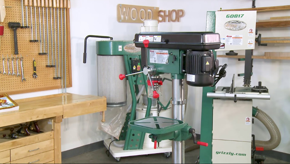
We are proud to offer the Grizzly Model G7943/44 12 Speed Heavy-Duty Drill Press. The Model G7943/44 is part of a growing Grizzly family of fine woodworking machinery. When used according to the guidelines set forth in this manual, you can expect years of trouble-free, enjoyable operation and proof of Grizzly’s commitment to customer satisfaction.
The Model G7943 is a bench version and the G7944 is a floor version. The drill press has a 3⁄4 H.P., 1720 R.P.M. motor capable of producing a 3⁄4" hole in steel. There are 12 spindle speeds ranging from 140 to 3050 R.P.M. A work light, cast iron table, and 14" swing all make this a great drill press for most drilling applications.
Parts List
001 | P7943001 | BASE |
002 | PB32M | HEX BOLT M10 X 25 |
003 | P7943003 | RACK |
003A | P7943003A | LONG RACK |
004 | P7943004 | COLUMN |
004A | P7943004A | LONG COLUMN |
005 | P7943005 | TABLE BRACKET |
006 | P7943006 | HANDLE |
007 | P7943007 | SETSCREW M3-1.0X 5 |
008 | P7943008 | SHAFT |
009 | PN01M | PIN M6 X 30 |
010 | PRP08M | NUT M6 |
011 | PW16 | WASHER M16 |
012 | P7943012 | HEX BOLT M16 X 40 |
013 | P7943013 | TABLE BOLT |
014 | P7943014 | TABLE ARM BRACKET |
015 | P7943015 | TABLE |
016 | P7943016 | CLAMP BOLT |
017 | P7943017 | GEAR |
018 | P7943018 | WORM GEAR |
019 | P7943019 | RACK RING |
020 | P7943020 | PIN STOP |
021 | P7943021 | SETSCREW M3-1.0X 10 |
022 | P7943022 | FEED SHAFT |
023 | P7943023 | DEPTH RING |
024 | PRP28M | ROLL PIN 5 X 40 |
025 | P7943025 | HANDLE BODY |
026 | P7943026 | HANDLE |
027 | P7943027 | KNOB |
028 | P7943028 | COLUMNSHOULDER SHORT |
028A | P7943028A | COLUMNSHOULDER LONG |
029 | P7943029 | SLIDEBAR BOLT |
030 | P7943030 | SETSCREW M5-1.5 X 10 |
032 | P7943032 | C-CLIP |
033 | P7943033 | SHIFTER BAR |
034 | P7943034 | SLIDEBAR BOLT |
035 | PB19M | HEX BOLT M8 X 24 |
036 | PW08 | WASHERM8 |
037 | PN03M | NUT M8 |
038 | PN08M | NUT M10 |
039 | P7943039 | SCREW SPECIAL SET |
040 | P7943040 | NUT M12 X 1.5 |
041 | P7943041 | NUT M12 X 1.5 |
042 | P7943042 | SPRING CAP |
043 | P7943043 | TORSION SPRING |
044 | P7943044 | SPRING COVER |
045 | P7943045 | SWITCH BOX |
046 | PS08M | SCREWM5 X 12 |
047 | P7943047 | SCREW ST4.2 X 9 |
048 | PS09M | SCREW M5 X 10 |
049 | P7943049 | CLAMP CORD |
050 | P7943050 | BODY |
051 | PB03M | HEX BOLT M8 X 16 |
052 | P7943052 | SHIFTER |
| 053 | P7943053 | SLIDE BAR |
| 054 | P7943054 | SLIDE BAR |
| 055 | P7943055 | MOTOR BASE |
| 056 | PW06M | WASHER M12 |
| 056A | PLW05M | LOCK WASHERM12 |
| 057 | PN09M | NUT M12 |
| 058 | P7943058 | MOTOR |
| 059 | P7943059 | MOTOR PULLEY |
| 060 | PK34M | KEY 5 X 20 |
| 061 | P7943061 | SETSCREW M3-1.0X 5 |
| 062 | P7943062 | V-BELT |
| 063 | P7943063 | CENTER SHAFT |
| 064 | P7943064 | BALL BEARING P6202 |
| 065 | P7943065 | BALL BEARING P6202 |
| 066 | P7943066 | C-CLIP |
| 067 | P7943067 | CENTER PULLEY |
| 068 | PW16 | WASHER M6 |
| 068B | PW16 | WASHER M6 |
| 069 | PS24M | SCREW M6 X 10 |
| 070 | PS08M | SCREW M5 X 12 |
| 071 | PW16 | WASHER M6 |
| 072 | P7943072 | KNOB |
| 073 | P7943073 | PULLEY COVER |
| 074 | P7943074 | V-BELT |
| 075 | P7943075 | PULLEY NUT |
| 076 | P7943076 | SPINDLE PULLEY |
| 077 | P7943077 | INSERT PULLEY |
| 078 | P7943078 | C-CLIP |
| 079 | P7943079 | BALL BEARING P6205 |
| 080 | P7943080 | SPACER |
| 081 | P7943081 | BALL BEARING P6205 |
| 082 | P7943082 | C-CLIP |
| 083 | P7943083 | ROUND NUT M17 X 1 |
| 084 | P7943084 | WASHER |
| 085 | P7943085 | BALL BEARING P6205 |
| 086 | P7943086 | RUBBER WSHR 62 X 50 X 2 |
| 087 | P7943087 | SPINDLE SLEEVE |
| 088 | P7943088 | BALL BEARING P6205 |
| 089 | P7943089 | SPINDLE |
| 090 | P7943090 | ARBOR |
| 091 | P7943091 | CHUCK |
| 092 | P7943092 | CHUCK KEY |
| 093 | P7943093 | LIGHT BODY |
| 094 | P7943094 | LIGHT BASE |
| 094A | P7943094A | SCREW |
| 095 | P7943095 | LIGHT SCREW |
| 096 | P7943096 | SWITCH BASE |
| 097 | P7943097 | SWITCH (LIGHT) |
| 098 | P7943098 | SWITCH MOTOR |
| 098B | P7943098B | SWITCH KEY |
| 099 | P7943099 | C-CLIP |
| 100 | P7943100 | PIN 18 AWG/3 METERS |
| 100B | P7943100B | WIRE GASKET |
| 100C | P7946100C | MOTOR CORD |
| 101 | PAW05M | ALLEN®WRENCH 5MM |
| 102 | PAWO3M | ALLEN®WRENCH 3MM |
| 103 | P7943103 | WEDGE |
| 104 | P7943104 | WARNING LABEL |
| 105 | P7946105 | WARNING/ID LABEL |
| 106 | P7943106 | SPEED CHARTLABEL |
| 107 | P7943107 | GRIZZLY BLACK/AL LABEL |
GRIZZLY MODEL G7943 12 SPEED DRILL PRESS
| Category | Feature | Specification |
|---|---|---|
| Design Type | Bench Model | - |
| Overall Dimensions | Table | 11-3/8" x 11-3/8" |
| Overall Height | 38" | |
| Overall Width | 14" | |
| Overall Depth | 24" | |
| Column Diameter | 3.150" | |
| Quill Diameter | 2.040" | |
| Shipping Weight | 160 lbs. | |
| Box Size | 32" L x 20-1/2" W x 11-1/2" H | |
| Footprint | 18" x 11" | |
| Construction | Table | Precision Ground Cast Iron |
| Column | Cylindrical Ground Steel | |
| Base & Head | Cast Iron | |
| Capacities | Spindle Travel | 3-1/4" |
| Max. Distance, Spindle to Base | 23" | |
| Max. Distance, Spindle to Table | 16" | |
| Spindle Taper | MT #2 | |
| Swing | 14" | |
| Chuck Size | 5/8" (16mm), keyed | |
| Number of Speeds | 12, Belt Controlled | |
| Speeds | 140, 260, 320, 380, 480, 540, 980, 1160, 1510, 1650, 2180, 3050 R.P.M. | |
| Drilling Capacity | 3/4" Diameter in Steel | |
| Motor | Type | TEFC Capacitor Start Induction |
| Horsepower | 3/4 H.P. | |
| Phase/Cycle | Single Phase / 60 Hz | |
| Voltage | 110V | |
| Amps | 9 | |
| R.P.M. | 1720 | |
| Power Transfer | V-Belt Drive | |
| Bearings | Shielded & Lubricated Ball Bearings | |
| Switch | Toggle ON/OFF Switch, w/ Safety Lock Tab | |
| Features | Table | 360° Swivel Around Table Center, 360° Swivel Around Support Column, Tilt -90° to + 90°, Lock Levers, Coolant Trough |
| Vertical Table Movement | Crank Handle Operated Rack and Pinion | |
| Illumination | 110 Volt Socket, Separately Switched | |
| T-Slot | 4 - 5/8" x 3-7/8", Accommodates 1/2" Clamping Kit | |
| Depth Gauge | On Feed Handle Hub, Inch Increments |
GRIZZLY MODEL G7944 12 SPEED DRILL PRESS
| Category | Feature | Specification |
|---|---|---|
| Design Type | Floor Model | - |
| Overall Dimensions | Table | 11-3/8" x 11-3/8" |
| Overall Height | 64" | |
| Overall Width | 14" | |
| Overall Depth | 24" | |
| Column Diameter | 3.150" | |
| Quill Diameter | 2.040" | |
| Shipping Weight | 172 lbs. | |
| Footprint | 18" x 11" | |
| Construction | Table | Precision Ground Cast Iron |
| Column | Cylindrical Ground Steel | |
| Base & Head | Cast Iron | |
| Capacities | Spindle Travel | 3-1/4" |
| Max. Distance, Spindle to Base | 49" | |
| Max. Distance, Spindle to Table | 31-1/2" | |
| Spindle Taper | MT #2 | |
| Swing | 14" | |
| Chuck Size | 5/8" (16mm), keyed | |
| Number of Speeds | 12, Belt Controlled | |
| Speeds | 140, 260, 320, 380, 480, 540, 980, 1160, 1510, 1650, 2180, 3050 R.P.M. | |
| Drilling Capacity | 3/4" Diameter in Steel | |
| Motor | Type | TEFC Capacitor Start Induction |
| Horsepower | 3/4 H.P. | |
| Phase/Cycle | Single Phase / 60 Hz | |
| Voltage | 110V | |
| Amps | 9 | |
| R.P.M. | 1720 | |
| Power Transfer | V-Belt Drive | |
| Bearings | Shielded & Lubricated Ball Bearings | |
| Switch | Toggle ON/OFF Switch, with Safety Lock Tab | |
| Features | Table | 360° Swivel Around Table Center, 360° Swivel Around Support Column, Tilt -90° to + 90°, Lock Levers, Coolant Trough |
| Vertical Table Movement | Crank Handle Operated Rack and Pinion | |
| Illumination | 110 Volt Socket, Separately Switched | |
| T-Slot | 4 - 5/8" x 3-7/8", Accommodates 1/2" Clamping Kit | |
| Depth Gauge | On Feed Handle Hub, Inch Increments |
Detailed Specifications
The Grizzly Heavy Duty Floor Drill Press G7944 is a powerful and accurate drilling machine, designed for heavy-duty applications. Here are its key features and specifications:
- 20-inch swing and 14-speed drilling capacity (170-3070 RPM)
- 3/4 HP, 110V, 1 phase motor for powerful performance
- Cast iron worktable (14-inch x 14-inch) with T-slots and locking handle for precision and stability
- Spindle travel of 4 inches with depth stop for accurate drilling
- Adjustable quill for easy tool changes and maintenance
- Built-in work light and convenient on/off switch for user comfort
- Sturdy and stable base with leveling feet for stability and versatility
- Weight: 217 lbs for durability and reliability
Unpacking
The Model G7943/44 is shipped from the manu-facturer in a carefully packed carton. If you dis-cover the machine is damaged after you’ve signed for delivery, immediately call Customer Service for advice. When you are completely satisfied with the condition of your shipment, you should inventory its parts.
WARNING: If moving this machine up or down stairs, the machine must be dis-mantled and moved in smaller pieces. Make sure floor and stair structures are capable of supporting the combined weight of the machine parts and the people moving them.
CAUTION: The G7943/7944 represents a heavy load at 160/172 pounds. Seek assistance before beginning assembly.
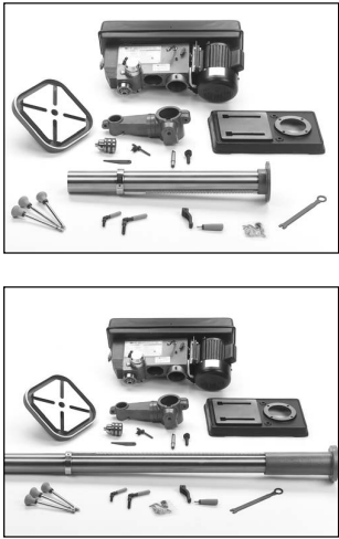
Piece Inventory
After all the parts have been removed from the carton, you should have
- Headstock
- Table Assembly
- Base
- Column Assembly
- Drill Chuck and Key
- Drift Key
- Allen Wrenches (2)
- Hex Bolts, M10 x 25 or 40 (4)
In the event that any nonproprietary parts are missing (e.g. a nut or a washer), we would be glad to replace them, or, for the sake of expediency, replacements can be obtained at your local hard-ware store.
Clean Up
The unpainted surfaces are coated with a waxy oil to protect them from corrosion during shipment. Remove this protective coating with a solvent cleaner or citrus-based degreaser such as Grizzly’s G7895 Degreaser. Avoid chlorine-based solvents as they may damage painted surfaces should they come in contact. Always follow the usage instructions on the product you choose for clean up.
WARNING: Do not use gasoline or other petroleum-based solvents. They have low flash points which make them extremely flamma-ble. A risk of explosion and burning exists if these products are used. Serious personal injury may occur if this warning is ignored.
CAUTION: Many of the solvents commonly used to clean machinery can be toxic when inhaled or ingest-ed. Always work in well-ventilated areas far from potential ignition sources when dealing with sol-vents. Use care when dis-posing of waste rags and towels to be sure they do not create fire or environ-mental hazards.
WARNING: Do not smoke while using solvents. A risk of explo-sion or fire exists and may result in serious personal injury.
Site Considerations
- FLOOR LOAD
Your Model G7943/7944 represents a moderate weight load in a small footprint. Most commercial or home shop floors should be sufficient to carry the weight of the Model G7943/7944. If you ques-tion the strength of your floor, you can opt to rein-force it. Ensure that the stand or bench you use with the Model G7943 is capable of supporting the machine. - WORKING CLEARANCES
Working clearances can be thought of as the dis-tances between machines and obstacles that allow safe operation of every machine without lim-itation. Consider existing and anticipated machine needs, size of material to be processed through each machine, and space for auxiliary stands and/or work tables. Also consider the relative position of each machine to one another for effi-cient material handling. Be sure to allow yourself sufficient room to safely run your machines in any foreseeable operation. - LIGHTING AND OUTLETS
Lighting should be bright enough to eliminate shadow and prevent eye strain. Electrical circuits should be dedicated or large enough to handle combined motor amp loads. Outlets should be located near each machine so power or extension cords are not obstructing high-traffic areas. Be sure to observe local electrical codes for proper installation of new lighting, outlets, or circuits.
CAUTION: Make your shop “child safe.” Ensure that your workplace is inaccessible to youngsters by closing and locking all entrances when you are away. Never allow visitors in your shop when assembling, adjust-ing or operating equip-ment.
Assembly
Beginning Assembly
- WARNING: Disconnect power to the machine when perform-ing any maintenance, assembly or adjust-ments. Failure to do this may result in serious personal injury.
- WARNING: Keep loose clothing rolled up and out of the way of machinery and keep hair pulled back.
- WARNING: Wear safety glasses dur-ing the entire assembly process. Failure to com-ply may result in serious personal injury.
Most of your G7943/44 Drill Press has been assembled at the factory, but some parts must be assembled or installed after delivery. We have organized the assembly process into steps. Please follow along in the order presented here.
TOOLS REQUIRED: 11⁄16" open end wrench, rub-ber or wooden mallet and (2) Allen wrenches (supplied).
Column/Base
The G7944 is a floor model and must be secured to the floor using anchor bolts, or the base should be secured to a piece of plywood. The G7943 must be secured to a bench.
WARNING: Do not use a mobile base. Drill presses are extremely top heavy. A stable base is required to prevent serious bodily injury.
- Unplug machine before assembly.
G7944: Secure the base to the floor using the appro-priate anchor bolts. or Secure base to a piece of 4' x 4' x 3⁄4" plywood. Using the holes in the base as a guide, drill and bolt the base to the back center of the plywood using carriage bolts.
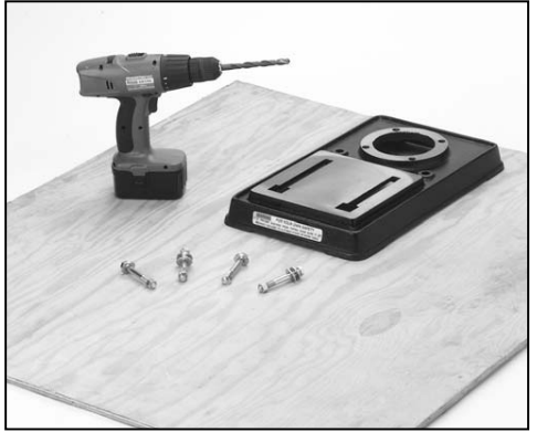
G7943: Secure base to a bench top capable of holding approximately 160 lbs plus the weight of the workpiece. Using the holes in the base as a guide, drill and bolt the base to the bench top using carriage bolts.
- Place the column on the base and line up the mounting holes. Insert and tighten the M10-1.5 hex head bolts with a wrench.
Table Support
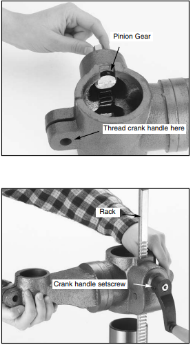
- Thread the 12mm table lock handle 3 turns into the table support bracket as shown in Figure 4.
- Insert the pinion gear into the hole on the side of the table support bracket from the inside, starting with the pinion shaft as shown in Figure 4. Align setscrew in crank handle with flat on pinion gear shaft and secure using the 3mm Allen® wrench provided as shown in Figure 5.
- Examine the rack and note that the gear teeth extend farther on one end than the other. The end of the rack where the gear teeth are closest to the end should be posi-tioned down. Insert the rack into the table support bracket and align it with the pocket as shown in Figure 5. The gear teeth on the rack must also face out.
- Slide the table support bracket onto the col-umn while holding the rack in place. Allow the bracket to go down until the bottom of the rack contacts the shoulder on the column support as shown in Figure 5. Secure the table support bracket with the lock handle.
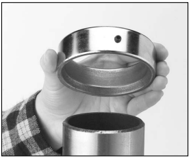
- Slide the column ring onto the column with the inside bevel in the down position as shown in Figure 6. Adjust the ring until the tip of the rack fits inside the bevel. Tighten the setscrew on the ring.
NOTICE: Use caution when tightening setscrew. Over tightening will split the column ring.
Headstock
CAUTION: The headstock repre-sents a heavy load. Seek assistance before begin-ning this step.
- There is a pocket in the bottom of the head-stock for the column to be placed. Seek assistance to help position the headstock over the column. Allow the headstock to slide down until it stops (approximately 4").
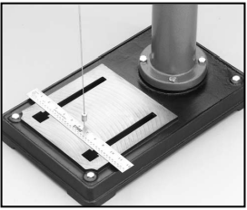
- Position the headstock directly over the base by using a plumb bob. Use a measuring tape or ruler across the drill press base to find its center. Suspend the plumb line from the cen-ter of the headstock label and lower the bob until it is near the tape/ruler as shown in Figure 7. Adjust headstock from side to side until the tip is equidistant from both the left and right sides.
- Tighten the two setscrews shown in Figure 8
Handles: Three handles are supplied with the drill press. Thread them into the handle hub.
Installing Light Bulb
The Model G7943/44 has a light socket that uti-lizes standard sized 40 watt bulbs. Before installing a light bulb, unplug the drill press. Secure bulb in opening behind the spindle.
WARNING: Use only bulbs that are “safety coated” and shatter resistant. The bulb will be exposed at the bottom of the head casting which helps with illumination. Impacts with a bulb not “safety coated” may shatter, exposing the electrical filaments and creating an electrical shock hazard.
Drill Chuck and Arbor
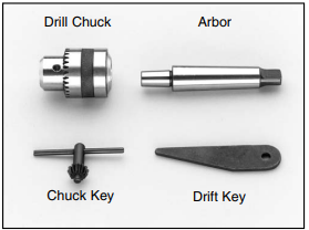


The drill chuck attaches to the drill spindle by means of a drill chuck arbor. Matched tapers on the arbor and back of the chuck create an almost permanent assembly when properly joined. To assemble the drill chuck and mount it to the spin-dle, carefully follow the instructions below:
- The drill chuck, arbor and spindle socket must be thoroughly cleaned and dried before assembly. It is recommended that mineral spirits be used for this task. Refer to the safe-ty warnings on the container of the mineral spirits. Failure to clean the mating sur-faces may result in separation and an unsafe condition. Separation is usually caused by oil or grease on the taper.
- Use the provided chuck key to adjust the jaws of the chuck until they are well inside the drill chuck body.
- Place the drill chuck on a workbench face down. The arbor has a short taper and a long taper. Place the short taper into the socket in the back of the drill chuck and tap with a rub-ber or wooden mallet as shown in Figure 10. If the chuck fails to remain secure on the arbor, repeat step 1 and 2.
- Slide the arbor into the spindle socket while slowly rotating drill chuck. The socket has a rectangular pocket in which the tang (or flat portion of the arbor) fits into. Once the tang is oriented correctly the drill chuck will not rotate without turning the spindle.
- Tap the end of the drill chuck with a rubber or wooden mallet to seat it as shown in Figure 11.
CAUTION: DO NOT use a steel hammer on the drill chuck to seat it onto the spindle. Damage will occur to the chuck and/or spindle which may make them unusable or unsafe.
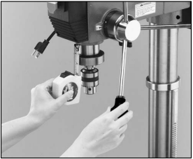
Arbor Removal
A drift key is included to aid in the drill chuck arbor removal.
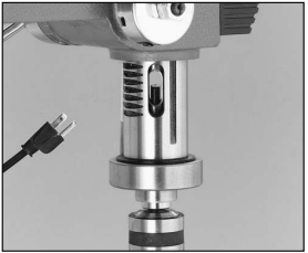
- Rotate the spindle handles until the slot is exposed in the side of the quill.
- Rotate the spindle until the inner slot is aligned with the outer as shown in Figure 12. You will see through the spindle when the slot is properly aligned.
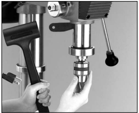
- Insert the drift key into the slot and allow the quill to rise, trapping the drift key. Hold the drill chuck with one hand and tap on the drift key with a hammer as shown in Figure 13.
Description
The Grizzly Heavy Duty Floor Drill Press G7944 is a versatile and reliable drilling machine, suitable for a wide range of applications, from woodworking and metalworking to construction and maintenance. Its powerful motor and robust construction ensure consistent and accurate performance, while its user-friendly design and features make it easy to operate and maintain. Whether you're drilling holes in wood, metal, or plastic, the Grizzly Heavy Duty Floor Drill Press G7944 is a reliable and efficient tool that will help you get the job done right.
Adjustments of Floor Drill Press G7944
Speed Changes
Unplug the drill press before changing speeds. The drill press has 12 speeds ranging from 140 to 3050 R.P.M. There is a speed chart located under the belt guard. Refer to the chart while reading these instructions.
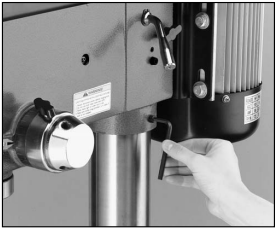
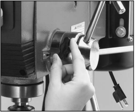
- Loosen the belt tension lock knobs on both sides of the headstock by turning counter-clockwise as shown in Figure 14.
- The motor should be free to move. Rotate the belt tension lever counterclockwise to take tension off the V-belts as shown in Figure 15.
- Locate the desired speed on the chart and move the V-belts to the desired V-grooves on the motor, idler and spindle pulleys.
- Rotate the belt tension lever until the belts are tight. Tighten both lock knobs.
- Close the cover.
Depth Stop
Your drill press comes with a depth stop adjust-ment for use when drilling.
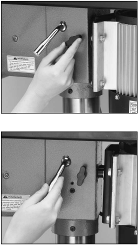
- Loosen the depth collar lock knob as shown in Figure 16.
- Secure the wood stock you will be drilling onto the drill press table.
- With the desired bit installed, lower the spin-dle until the tip of the bit just touches the wood stock you will be drilling. Hold the spin-dle in this position.
- Turn the depth collar to the desired depth indicated by the scale on the collar. Secure the collar by tightening the lock knob.
- Remove the wood stock and test the depth stop by measuring how far the spindle travels when the handles are rotated as shown in Figure 17.
You can also lock the spindle in the down posi-tion for operations such as spindle sanding.
- Loosen the depth collar lock knob as shown in Figure 16.
- Rotate the spindle to the desired depth and hold it steady.
- Rotate the the collar clockwise until it stops, and tighten the lock knob.
- Slowly release the drill press handle. The spindle should not move.
Table Adjustment
The table can be adjusted for height, rotation and angle.
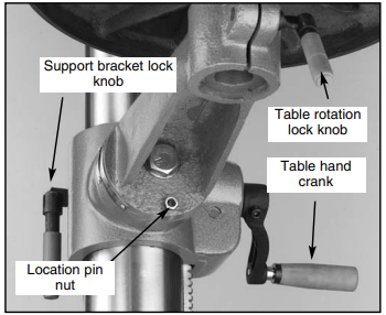
- Loosen the support bracket lock knob. Turn the table hand crank to lift or lower the table as shown in Figure 18.
- Always lock the support bracket in place before operating the machine.
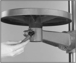
Adjust rotation
- Loosen the lock handle located under the table as shown in Figure 19. Rotate the table the desired amount.
- Always lock the table rotation in place before operating the machine.
Adjust angle
- Turn the nut indicated by the arrow in Figure 18, in a clockwise direction. This will draw the location pin out of the casting. Once loose, pull the pin and nut out, and set it in a safe place until needed.
- Loosen the large bolt in the center of the sup-port bracket.
- Rotate the bracket to the desired angle. Use the scale on the side of the bracket or a pro-tractor to set the angle. Lock in place by tightening the bolt.
When repositioning the table to 0˚ position, loosen the large bolt in the center of the support casting. Rotate the support casting until the degree scale reads 0˚. Carefully tap the location pin back into the hole from which it came until it stops. Unscrew the nut on the location pin until it is flush with the end of the threads. This will pro-tect the threads when you tap it into place with a hammer. Turn the nut clockwise until it is snug against the casting and then tighten the large bolt in the center. The table is now set to the factory pre-set angle.
Operations
Test Run
- Once assembly is complete and adjustments are done to your satisfaction, you are ready to test run the machine.
- Turn on the power supply at the main panel. Flip the START button. Make sure that your finger is poised on the paddle switch, just in case there is a problem. The drill press should run smoothly, with little or no vibration or rubbing noises. Strange or unnatural noises should be investigat-ed and corrected before operating the machine further.
- If you cannot easily locate the source of an unusual noise or vibration, contact our service department for help.
Drill Bit Changes
Make sure to secure the bit firmly in place. When changing bits, proceed as follows:
- Disconnect the machine from power source.
- Open the chuck wide enough to accept a new bit.
- Install the bit so the chuck jaws will grab as much of the bit shank as it can. Do not allow the chuck to grab the fluted body of the drill bit. Make sure small drill bits do not get trapped between the edges of two jaws.
- Tighten the chuck with the chuck key using any of the three key end locations.
- Remove the chuck key and reconnect power source.
- Reverse steps to remove drill bit.
Grizzly Heavy Duty Maintenance
General
Regular periodic maintenance on your Model G7943/44 will ensure its optimum performance. Make a habit of inspecting your machine each time you use it. Check for the following conditions and repair or replace when necessary:
- Loose mounting bolts.
- Worn switch.
- Worn or damaged cords and plugs.
- Damaged V-belt.
- Any other condition that could hamper the safe operation of this machine.
Tables
The nonpainted surfaces on the Model G7943/44 should be protected against rust and pitting. Wiping the machine clean after every use ensures that wood dust will not trap moisture against bare metal surfaces.
Some woodworkers recommend using automo-tive paste wax on exposed steel and cast iron sur-faces. The wax provides a layer of protection, as well as reducing friction between lumber and the table, making cuts faster and smoother. Avoid waxes that contain silicone or other synthetic ingredients. These materials can find their way into lumber that is being worked, and can make staining and finishing difficult. If you use paste wax, make sure that it is 100% Carnauba wax.
Lubrication
Since all bearings are shielded and permanently lubricated, simply leave them alone until they need to be replaced. Do not lubricate them.
V-Belt
Inspect regularly for tension and wear. Check pul-leys to ensure that they are properly aligned. See pulley/V-belt sections for proper tension and pul-ley alignment procedures.
Grizzly Closure
The following pages contain general machine data, parts diagrams/lists, troubleshooting guide and Warranty/Return information for your Model G7943/44.
- If you need parts or help in assembling your machine, or if you need operational information, we encourage you to call our Service Department. Our trained service technicians will be glad to help you
- If you have comments dealing specifically with this manual, please write to our Bellingham, Washington location using the address in Section 3 Introduction.
We have included some important safety mea-sures that are essential to this machine’s opera-tion. While most safety measures are generally universal, Grizzly reminds you that each work-shop is different and safety rules should be con-sidered as they apply to your specific situation. We recommend you keep a copy of our current catalog for complete information regarding Grizzly's warranty and return policy. If you need additional technical information relating to this machine, or if you need general assistance or replacement parts, please contact the Service Department listed in Section 3: General Information.
WARNING: Operating this equipment has the potential for flying debris to cause eye injury. Always wear safety glasses or goggles when oper-ating equipment. Everyday glasses or read-ing glasses only have impact resistant lens-es, they are not safety glasses. Be certain the safety glasses you wear meet the appro-priate standards of the American National Standards Institute (ANSI).
WARNING: The Model G7943/44 was specifically designed for drilling operations. DO NOT MODIFY AND/OR USE THIS MACHINE FOR ANY OTHER PURPOSE. Modifications or improper use of this tool will void the war-ranty. If you are confused about any aspect of this machine, DO NOT use it until you have answered all your questions or seri-ous personal injury may occur.
WARNING: Like all power tools, there is danger asso-ciated with the Model G7943/44. Accidents are frequently caused by lack of familiarity or failure to pay attention. Use this tool with respect and caution to lessen the pos-sibility of operator injury. If normal safety precautions are overlooked or ignored, serious personal injury may occur.
Drill Press G7944 Troubleshooting
Here are some common problems and solutions for the Grizzly Heavy Duty Floor Drill Press G7944:
- Problem: The drill press is not starting.
- Solution: Check the power cord and outlet for any issues. Make sure the power switch is in the "on" position. If the problem persists, contact a professional technician.
- Problem: The drill press is vibrating excessively.
- Solution: Check the leveling feet and make sure they are securely tightened. If the problem persists, check the belts and pulleys for any signs of wear or damage. Contact a professional technician if necessary.
- Problem: The drill press is making unusual noises.
- Solution: Check the belts and pulleys for any signs of wear or damage. Check the spindle and bearings for any signs of wear or damage. If the problem persists, contact a professional technician.
Warranty
Grizzly Industrial, Inc. warrants every product it sells for a period of 1 year to the original purchaser from the date of purchase. This warranty does not apply to defects due directly or indirectly to misuse, abuse, negligence, accidents, repairs or alterations or lack of maintenance. This is Grizzly’s sole written warranty and any and all warranties that may be implied by law, including any merchantability or fitness, for any particular purpose, are hereby limited to the duration of this written warranty. We do not warrant or represent that the merchandise complies with the provisions of any law or acts unless the manufacturer so warrants. In no event shall Grizzly’s liability under this warranty exceed the purchase price paid for the product and any legal actions brought against Grizzly shall be tried in the State of Washington, County of Whatcom.
Pros & Cons
Pros
- Powerful and accurate drilling performance
- Robust and durable construction
- User-friendly design and features
- Versatile and suitable for a wide range of applications
- Affordable price compared to similar models
Cons
- Heavy and difficult to move around
- May require professional assembly and maintenance
- May produce noise and vibration during operation
Customer Reviews about Grizzly Heavy Duty Floor Drill Press G7944
The Grizzly Heavy Duty Floor Drill Press G7944 has received positive reviews from many satisfied customers, who praised its performance, durability, and value for money. However, some customers reported issues with assembly, noise, and vibration, and recommended professional installation and maintenance. Some customers also suggested improvements in the instructions and manual.
Faqs
What are the main features of the Grizzly Heavy Duty Floor Drill Press G7944?
How do I assemble the Grizzly Heavy Duty Floor Drill Press G7944?
How do I change the drill speed on the Grizzly Heavy Duty Floor Drill Press G7944?
What are the electrical requirements for the Grizzly Heavy Duty Floor Drill Press G7944?
What are the best practices for ensuring accurate drilling with the Grizzly Heavy Duty Floor Drill Press G7944?
Can the Grizzly Heavy Duty Floor Drill Press G7944 be used for sanding or other operations?
How do I adjust the table height and angle on the Grizzly Heavy Duty Floor Drill Press G7944?
What should I do if I experience excessive vibration or noise while using the Grizzly Heavy Duty Floor Drill Press G7944?
How do I replace the chuck on the Grizzly Heavy Duty Floor Drill Press G7944?
What is the warranty on the Grizzly Heavy Duty Floor Drill Press G7944, and what does it cover?
Leave a Comment