Intex Sand Filter Pump SF80110-1 User Manual | Specs
Content
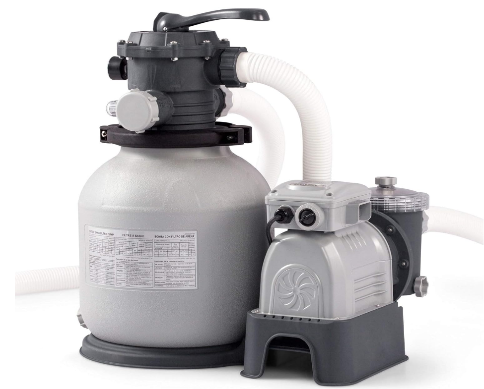
Introducing the Intex Sand Filter Pump SF80110-1
The Intex Sand is an efficient solution for keeping your above-ground pool water clean and clear. With a powerful flow rate of 2,100 gallons per hour, this pump utilizes sand filtration technology to effectively remove impurities. It features a user-friendly six-function control valve for easy operation, including filtering, backwashing, and draining. Designed for durability and low maintenance, the Intex Sand Filter Pump SF80110-1 is priced at approximately $159.99.
PARTS REFERENCE
Before assembling your product, please take a few minutes to check the contents and become familiar with all the parts.

Parts shown on this page are supplied with the pool package and are shown here for assembly purposes only.

NOTE: Drawings for illustration purposes only. Actual products may vary. Not to scale.
No tools are required for the assembly.
If this pump was not purchased as part of a pool set, the above parts can be ordered at https://www.intexcorp.com if needed.
REF. NO. | DESCRIPTION | QTY. | SPARE PART NO. | ||
SF80110-1 | SF70110-1 | SF60110-1 | |||
1 | PRESSURE GAUGE | 1 | 11411 | 11224 | 11224 |
2 | 6-WAY VALVE | 1 | 11378 | 11496 | 11496 |
3 | DRAIN OUTLET COVER | 1 | 11131 | 11131 | 11131 |
4 | CLAMP | 1 | 11380 | 11380 | 11380 |
5 | TANK O-RING | 1 | 11379 | 11379 | 11379 |
6 | SAND SHIELD | 1 | 11382 | 11382 | 11382 |
7 | CENTER PIPE HUB | 1 | 11815 | 11813 | 11814 |
8 | LATERAL | 10 | 11484 | - | - |
12 | - | 11384 | 11384 | ||
9 | DRAIN VALVE CAP | 1 | 11456 | 11456 | 11456 |
10 | DRAIN VALVE O-RING | 1 | 11385 | 11385 | 11385 |
11 | L-SHAPE O-RING | 4 | 11228 | 11228 | 11228 |
12 | HOSE WITH NUTS | 2 | 11009 | 11009 | 11009 |
13 | SAND FILTER INTERCONNECTING HOSE | 1 | 11820 | 11388 | 11535 |
14 | LEAF TRAP NUT | 1 | 11822 | 11479 | 11479 |
15 | LEAF TRAP O-RING | 1 | 11824 | 11232 | 11232 |
16 | BASKET | 1 | 11821 | 11260 | 11260 |
17 | FILTER HOUSING NUT | 1 | 11261 | 11261 | 11261 |
18 | L-SHAPE O-RING | 1 | 11412 | 11412 | 11412 |
19 | AIR RELEASE VALVE/SEDIMENT RELEASEVALVE | 2 | 10460 | 10460 | 10460 |
20 | VALVE O-RING | 2 | 10264 | 10264 | 10264 |
21* | PLUNGER VALVE (HOSE O-RING & STEP WASHER INCLUDED) | 2 | 10747 | 10747 | 10747 |
22* | HOSE O-RING | 2 | 10262 | 10262 | 10262 |
23* | STEP WASHER | 2 | 10745 | 10745 | 10745 |
24* | STRAINER NUT | 2 | 10256 | 10256 | 10256 |
25* | FLAT STRAINER RUBBER WASHER | 2 | 10255 | 10255 | 10255 |
26* | THREADED STRAINERCONNECTOR | 1 | 11235 | 11235 | 10744 |
27* | ADJUSTABLE POOL INLET JET NOZZLE | 1 | 12369 | 12369 | 12369 |
28* | ADAPTOR B | 2 | 10722 | 10722 | 10722 |
29* | STRAINER CONNECTOR | 1 | 11070 | 11070 | 11070 |
30* | POOL INLET JET NOZZLE | 1 | 12364 | 12364 | 12364 |
31* | STRAINER GRID | 1 | 11072 | 11072 | 11072 |
32 | SCREW | 2 | 11381 | 11381 | 11381 |
33 | PUMP MOTOR & CONTROL | 1 | 12491EG | 12487EG | 12489EG |
34 | PRE-FILTER ASSEMBLY | 1 | 11826 | 11371 | 11371 |
35 | LEAF TRAP COVER | 1 | 11823 | 11480 | 11480 |
36 | SAND FILTER PUMP MOTOR INLET O-RING | 2 | 11457 | 11457 | 11457 |
37 | SAND FILTER PUMP TANK | 1 | 11804 | 11802 | 11803 |
38 | SAND FILTER PUMP TANK BASE | 1 | 11816 | 11800 | 11801 |
39* | AIR JET VALVE | 1 | 12363 | 12363 | 12363 |
40* | STRAINER GRID | 1 | - | - | 10253 |
41 | PRE-FILTER HOUSING | 1 | 12100 | 12099 | 12099 |
42* | INLET THREADED AIR CONNECTOR | 1 | 12371 | 12372 | 12372 |
43* | POOL INLET AIR ADAPTOR | 1 | 12368 | 12368 | 12368 |
44* | INLET STRAINER CONNECTOR | 1 | 12365 | 12365 | 12365 |
45* | AIR JET VALVE CAP (NOT SHOWN) | 1 | 12373 | 12373 | 12373 |
" * ": Optional.
When ordering parts, be sure to quote the model number and part numbers.
Description
The Intex Sand Filter Pump SF80110-1 is built with durability and efficiency in mind. The pump features a robust sand filter tank that is resistant to corrosion, ensuring long-lasting performance. The 0.95 HP motor provides powerful circulation and filtration, while the easy-to-use control valve allows for simple operation and maintenance. The pump also includes a built-in timer for automated operation, making it convenient for pool owners who want a hassle-free maintenance routine.
POOL OUTLET
STRAINER & PLUNGER VALVE SETUP (optional)
The strainer grid prevents large objects from jamming and/or damaging the filter pump. If your pool has an inflatable top ring, install the strainer, nozzle and plunger valve before inflating the pool liner top ring. The part numbers here onward refer to the parts depicted in the Parts List section of this manual. To install, do the following:

- In a counter-clockwise motion unscrew plunger valve union from the threaded strainer connector (26) (see drawing 1). Be careful not to lose the step rubber washer (23). Place the plunger valve on the ground in a safe place.
- In a counter-clockwise motion unscrew the strainer nut (24) from the threaded connector (26). Leave the flat washer (25) on the connector (26).
- Install the strainer and plunger valve at the lower position of pool outlet (marked "+"). From the inside of the pool liner insert the connector (26) into one of the pre-cut holes with the washer remaining on the connector to be placed against the inside of the liner wall.
- Before assembly, lubricate the threads with a petroleum jelly. With the flat side of the strainer nut (24) facing the outside wall of the liner in a clockwise motion screw the strainer nut (24) back onto the threaded connector (26) (see drawing 2).
- Finger tighten the strainer nut (24) onto the threaded connector (26).
- Grasp the plunger valve assembly. Make sure the step washer (23) is in place.
- In a clockwise motion screw the plunger valve union back onto the threaded connector (26) (see drawing 3).
- In a clockwise motion turn the plunger valve handle to close position. Ensure the plunger valve is securely closed. This will prevent water from flowing out during filling of the pool (see drawing 4).
POOL INLET
NOZZLE & PLUNGER VALVE SETUP (optional)

- In a counter-clockwise motion unscrew plunger valve union from the inlet threaded air connector (42) (see drawing 5). Be careful not to lose the step rubber washer (23). Place the plunger valve on the ground in a safe place.
- In a counter-clockwise motion unscrew the strainer nut (24) from the inlet threaded air connector (42). Leave the flat washer (25) on the connector (42).
- Install the nozzle and plunger valve at the upper position of pool inlet. From the inside of the pool liner insert the nozzle union (27 & 42) into one of the pre-cut holes with the washer remaining on the connector to be placed against the inside of the liner wall.
- Before assembly, lubricate the threads with a petroleum jelly. Then, with the flat side of the strainer nut (24) facing the outside wall of the liner in a clockwise motion screw the strainer nut (24) back onto the inlet threaded air connector (42) (see drawing 6).
- Finger tighten the adjustable pool inlet jet nozzle (27) and the strainer nut (24) onto the inlet threaded air connector (42).
- Grasp the plunger valve assembly. Make sure the step washer (23) is in place.
- Screw the air jet valve (39) over the inlet threaded air connector (42). NOTE: Make sure the air jet valve is securely tighten and facing up. In a clockwise motion screw the plunger valve union back onto the inlet threaded air connector (42) (see drawing 7).
- In a clockwise motion turn the plunger valve handle to close position. Ensure the plunger valve is securely closed. This will prevent water from flowing out during filling of the pool (see drawing 8).
- Adjust the direction of nozzle head pointing away from the pool outlet for a better circulation result
(see drawing 9). - The pool liner is now ready to fill with water. Consult the above-ground-pool owner’s manual for filling instructions.
SPECIFICATIONS
The sand filter removes suspended particles but does not sanitize your pool. Pool chemistry is a specialized area and you should consult your local pool service specialist for details.
Model: | SF80110-1 | SF70110-1 | SF60110-1 |
Power: | 110-120 Volt AC | 110-120 Volt AC | 110-120 Volt AC |
Amperage: | 2.0 A | 4.0 A | 4.8 A |
Maximum working pressure: | 2 bar (30 psi) | 2 bar (30 psi) | 2 bar (30 psi) |
Effective filtering area: | 0.07 m2 (0.79 ft2) | 0.1 m2 (1.07 ft2) | 0.13 m2 (1.44 ft2) |
Maximum Flow Rate: | 6055 LPH (1600 GPH) | 8140 LPH (2150 GPH) | 9275 LPH (2450 GPH) |
Recommended filtering media quantity: | No.20 silica sand 23 Kg (50 Lbs) or glass sand 16 Kg (35 Lbs). | No.20 silica sand 35 Kg (77 Lbs) or glass sand 25 Kg (55 Lbs). | No. 20 silica sand 55 Kg (121 Lbs) or glass sand 38 Kg (84 Lbs). |
Recommended filtering media (Not included): | No. 20 silica sand or glass sand. Particle size range 0.45 to 0.85 mm (0.018 to 0.033 inches). Uniformity Coefficient less than 1.75. | ||
Limited Warranty: | see “Limited Warranty” | ||
NOTE: NOT SUITABLE FOR USE WITH KCP-LOW -SALT AUTOMATIC SALTWATER SYSTEM (MODEL 6110/6220).
SETUP INSTRUCTIONS
TOOLS REQUIRED: One (1) Phillips screwdriver
Pump location and mounting:
- The system must be installed on a solid level and vibration-free base.
- Provide a location protected from the weather, moisture, flooding and freezing temperature.
- Provide adequate access, space and lighting for routine maintenance.
- The pump motor requires free circulation of air for cooling. Do not install the pump in a damp or non-ventilated location.
A team of 2 or more people is recommended for setting up this product.
Motor pre-filtering assembly setup
- Remove the sand filter and its accessories from the packaging carefully and inspect for any visible damage. For missing or damaged parts contact the appropriate Intex Service Center listed in the separate “Authorized service Centers” sheet.
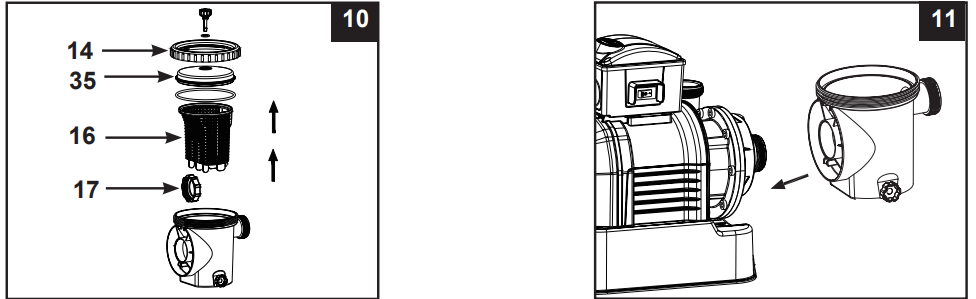
- In a counter-clockwise motion unscrew the leaf trap cover (14) from the pre-filter housing. Take out the basket (16) and filter housing nut (17) (see drawing 10).
Connect the pre-filter housing to the motor water inlet. Note: Align the connector in the pre-filter housing with the water inlet on the motor (see drawing 11).
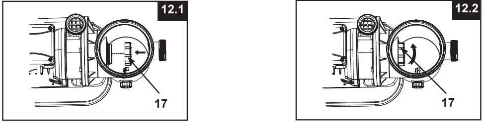
In a clockwise motion screw filter housing nut (17) onto the motor water inlet (see drawings 12.1 & 12.2).
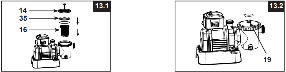
Replace the basket (16) and leaf trap cover (14) back to the pre-filter housing (see drawings 13.1 & 13.2).
Sand tank installation
- Place the tank support base on the selected location.
- Place the tank on the tank support base (see drawing 14.1).
Connect the motor pre-filtering assembly unit to the tank support base (see drawing 14.2).
NOTE: Ensure the pre-filter housing water inlet hose connection is facing towards the pool.
IMPORTANT: Some countries, especially in the European community, require the product to be secured to the ground or to a base in a permanent upright position. Check your local authorities to determine if there is a regulation in your area regarding above-the-ground swimming pool filter-pumps. If yes, then the product can be mounted to a platform using the two holes located in the base. See drawing 14.3.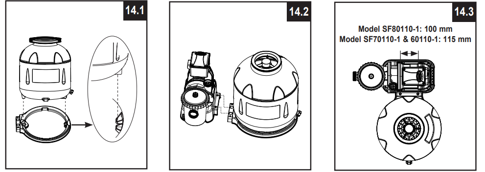
The product can be mounted on a cement base or onto a wooden plat form to prevent accidental falling over.
- The mounting holes are 6.4 mm in diameter and spaced 100 mm for model SF80110-1 (spaced 115 mm for model SF70110-1 & SF60110-1) apart.
- Use two bolts and lock nuts with a maximum of 6.4 mm in diameter.
Sand loading
IMPORTANT: Use No. 20 silica sand or glass sand with particle size range 0.45 to 0.85 mm (0.018 to 0.033 inches) and a Uniformity Coefficient less than 1.75.
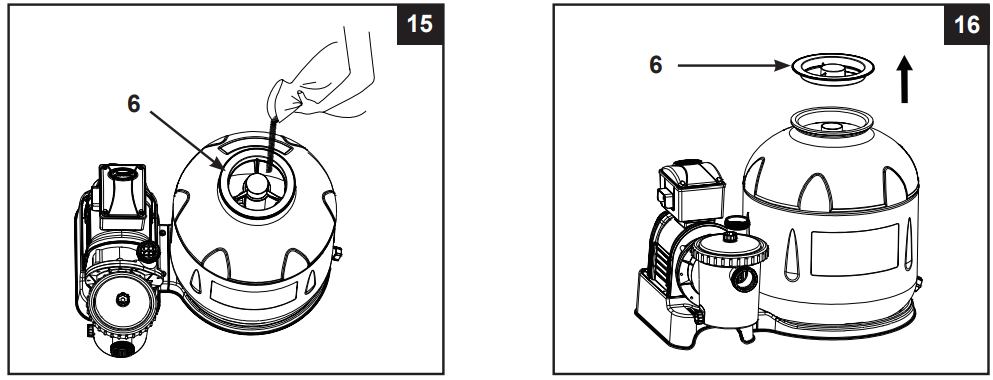
NOTE: Before loading the tank with sand, ensure the center pipe hub assembly is securely in place at the bottom of the tank, and vertically centered inside the tank.
- Place the sand shield (6) over the top of the center pipe. Pour the sand into the tank at a slow rate (see drawing 15).
Fill the tank approximately half way, remove the sand shield (6) from the top (see drawing 16).
- Evenly distribute the sand inside the tank, then fill the tank with some water to provide a cushioning effect when the remaining sand is poured in. This prevents the center pipe hub (7) from excessive shock (see drawing 17). Place the sand shield (6) back and continue to pour the sand into the tank.
Sand shall be filled between the “MAX” and “MIN” marked gauge on the center pipe. Evenly spread and level out the sand by hand (see drawings 17 & 18).
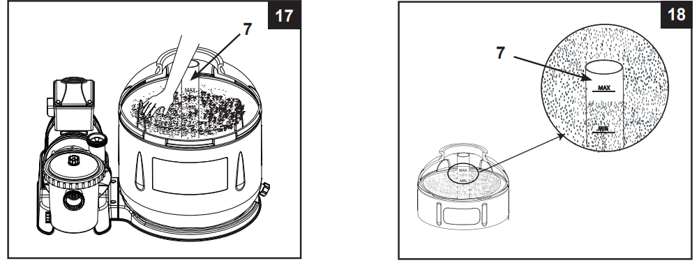
- Remove the sand shield (6).
- Wash away all sand around the top edge of the tank.
WARNING
Improper tank valve and clamp assembly could cause the valve and clamp to blow off and cause serious injury, property damage or death.
6-way valve installation
Lower the 6-way valve over the tank slowly, and ensure the bypass pipe protruding underneath the 6-way valve fits securely into the center pipe hub (7) top opening (see drawing 19).
IMPORTANT: There are three hose connection ports on the 6-way valve, ensure the outlet connection (from filter to the pool) on the valve is facing towards the pool, and the inlet connection (from motor to valve) is aligned with the motor outlet (see drawing 20).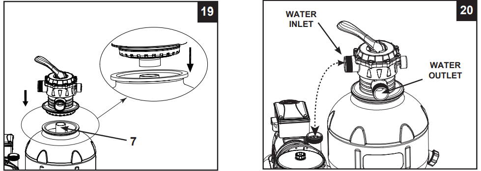
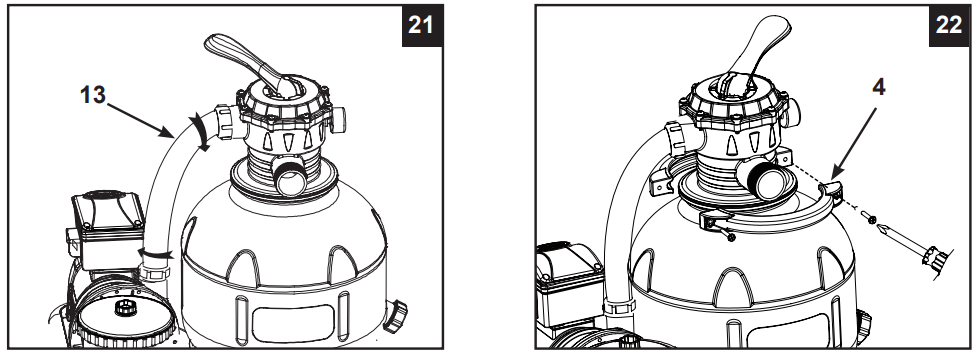
- Place an L-shape o-ring (11) on the 6-way valve inlet connection and on the pump motor outlet. In a clockwise motion connect the sand filter interconnecting hose (13) between the pump motor outlet and the 6-way valve inlet connection (see drawing 21).
Remove the clamp bolt, and install the clamp around the tank and 6-way valve flanges, then replace the clamp bolt and use a phillips screwdriver (not included) to tighten it (see drawing 22).
SAND FILTER PUMP HOSE CONNECTION SETUP
WARNING: Position this product away from the pool, so as to prevent children from climbing on it and accessing the pool.
The 6-way valve has three hose connection ports.
- Connect one hose (12) end to the pre-filter inlet and the other end of the hose to the lower plunger valve with the strainer. Ensure the hose nuts are securely tightened.
- Connect the second hose (12) between the 6-way valve water outlet and the upper plunger valve with the inlet-nozzle. Ensure the hose nuts are securely tighten.
- The third hose connection port (drain/waste outlet) on the 6-way valve shall be directed to a proper draining receptacle using a hose or pipe (not provided). Remove the drain cap before attaching the drain/waste hose or pipe.
- The sand filter pump is now ready to filter the pool.

For Pools with Dual Suction Outlets Configuration:
In order to comply with the requirement of the Virginia Grahame Baker Act (for USA and Canada), your pool is designed with dual suction outlets and one inlet fittings. Parts in grey highlight on this page are supplied with the pool set package and are shown here for assembly purposes only. If this pump was purchased as part of a pool set, refer to the pool owner’s manual for more details.

For NON-INTEX pool:
Connect the hose (12) to the pool inlet/outlet connection with a large hose clamp. Tighten securely.

For INTEX pool with 1-1/4” (32mm) connections/hoses:
Make sure the air jet valve (39) is securely tighten onto the pool inlet air adaptor (43) and facing up.
_connections-hoses_intex_sand_filter_pump_sf80110-1.png)
OPERATING INSTRUCTIONS
WARNING
- Risk of electric shock. Connect this product only to a grounding type receptacle protected by a ground-fault circuit interrupter (GFCI) or residual current device (RCD). Contact a qualified electrician if you cannot verify that the receptacle is protected by a GFCI/RCD. Use a qualified electrician to install the GFCI/RCD, which has a maximum rate of 30 mA. Do not use a portable residual current device (PRCD).
- To reduce the risk of electric shock, do not use extension cords, timers, plug adaptors or converter plugs to connect unit to electric supply; provide a properly located outlet.
- Do not attempt to plug in or unplug this product while standing in water or when your hands are wet.
- Never operate this product above the maximum working pressure stated on the filter tank.
- Always switch off pump before changing the 6-way valve position.
- Operating this product without water flowing through the system can cause a build up of hazardous pressure which can result in an explosive situation, serious injury, property damage or death.
- Never test this pump with compressed air. Never operate the system with water temperature above 35°C (95°F).
6-way valve positions and function
Valve Position | Function | Water Flow Direction |
FILTER (see drawing 23) | Normal filtration andregular vacuuming of pool | From pump throughfilter media to pool |
BACKWASH (see drawing 24) | Reverses water flow to clean filter media | From pump through filtermedia to valve waste/drain outlet |
RINSE (see drawing 25) | For initial startup cleaning of the sand, and leveling the sandbed afterbackwashing | From pump through filtermedia to valve waste/drain outlet |
WASTE (see drawing 26) | For vacuuming directly to waste, loweringpool level or to drainthe pool | From pump to valve waste/drain outlet bypassing the filter media |
RECIRCULATE (see drawing27) | For circulating waterback to pool without goingthrough the filtermedia | From pump throughvalve to pool bypassing the filter media |
CLOSED (see drawing 28) | Shuts off all flow to filter and pool “Do not use this setting with pump running” |


Initial startup and operation
Before operating, be sure that:
- All the hoses have been connected and tightened securely, and correct amount of filter sand have been loaded.
- The entire system is connected to a grounding type receptacle protected by a ground-fault circuit interrupter (GFCI) or residual current device (RCD).
CAUTION: The filter control valve has a closed position. The pump should never be on when the valve is in the closed position. If the pump is operated with the valve closed, explosive situation could exist.

- Turn both plunger valve handles fully counter-clockwise until they stop. This opens the valves to allow water to flow into the sand filter pump. With water flowing into sand filter pump, the water pressure will allow the air trapped inside to escape from the air release valves (19). When all the air has escaped water will flow out of the valves (19). When this occurs gently finger tighten the valves (19) in a clockwise direction.
- Ensure the drain/waste outlet on the 6-way valve is not covered and directed to a proper draining receptacle.
- Ensure the pump is off, depress the 6-way valve and turn 2 it to the “BACKWASH” position (see drawings 24 & 29).
IMPORTANT: To prevent damage to the 6-way valve, always depress the valve handle before turning.Always switch off pump before changing the 6-way valve position. - Switch on the pump (see drawing 30). Water is circulating backward through the sand media and to waste/drain outlet. Backwash until a clear flow of water is observed in the waste/drain outlet or through the drain sediment window.
NOTE: The initial backwash of the filter is recommended to remove any impurities or fine sand particles in the sand media. - Switch off the pump, change the 6-way valve to “RINSE” position (see drawing 25).
- Switch on the pump and run the pump for about one minute to level out the sand bed after backwashing the sand media.
- Switch off the pump, change the 6-way valve to “FILTER” position (see drawing 23).
- Switch on the pump. The system is now operating in the normal filtering mode. Run the pump until the desired pool water clearance is obtained and no more than 12 hours per day.
- Record the initial pressure gauge reading when the filter media is clean.
NOTE: During initial setup of the system, it may be necessary to backwash frequently due to unusual heavy dirt present in the water and sand. After that, as the filter removes dirt and impurities from the pool water, the accumulated dirt in the sand media will cause the pressure to rise and the flow to diminish. If there is no vacuuming device attached to the system and the pressure gauge reading is in the yellow zone it is time to backwash the sand media, see “BACKWASH” under “initial startup and operation” section. Vacuuming device (i.e. Intex auto pool cleaner) attached to the system may also cause the flow to diminish and the pressure to rise. Remove any vacuuming device from the system and check if the pressure gauge reading has dropped from the yellow zone to the green zone.
Operating the system under “TIMER” mode or manually:
To operate the sand filter pump in “FILTER” mode under “TIMER” control:
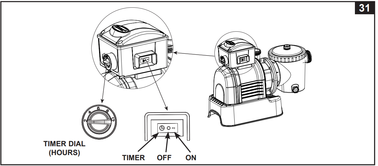
- Set the timer dial to the desired operating hours. See operation time table (see drawing 31).
- Turn on the pump by pressing the switch to “ ” position, the sand filter pump is now filtering the water and will stop after the operating hours are completed. The built-in timer will now operate for the number of hours selected at the same time each day.
- Operating hours can be re-adjusted if necessary. Follow step A – B.
To operate the sand filter pump manually (without the “TIMER” mode):
- Turn on the pump by pressing the switch to “-” position, the sand filter pump is now filtering the water.
To turn off the pump, press the switch to “O” position.
IMPORTANT
If you continue to experience difficulty, please contact our Consumer Service Department for assistance. See separate “Authorized Service Centers” sheet.
INTEX POOLS OPERATING TIME TABLE (WITHOUT INTEX SALTWATER SYSTEM)
This table shows the required operating time for average use of the sand filter pump with above ground pools. If the system is attached to an “Intex Saltwater System” unit, the filter pump running time should be longer than the required operating time of the Intex Saltwater System unit.
Pool Size | Water Capacity (Calculated at 90% for Frame Pool and 80% for Easy Set & Oval Pool) | Sand filter pump operating time (For one cycle) / (Hours) | ||||
(Gals) | (Liters) | SF80110-1 | SF70110-1 | SF60110-1 | ||
INTEX ABOVE GROUND POOLS (AGP’s) | ||||||
EASY SET® POOL | 457cmx84cm (15'x33") | 2587 | 9792 | 2 | - | - |
457cmx91cm (15'x36") | 2822 | 10681 | 2 | - | - | |
457cmx107cm (15'x42") | 3284 | 12430 | 2 | - | - | |
457cmx122cm (15'x48") | 3736 | 14141 | 4 | - | - | |
488cmx107cm (16'x42") | 3754 | 14209 | 4 | - | - | |
488cmx122cm (16'x48") | 4273 | 16173 | 4 | - | - | |
488cmx132cm (16'x52") | 4614 | 17464 | 4 | - | - | |
549cmx107cm (18'x42") | 4786 | 18115 | 4 | 2 | 2 | |
549cmx122cm (18'x48") | 5455 | 20647 | 4 | 2 | 2 | |
ROUND METAL FRAME POOL | 457cmx91cm (15'x36") | 3282 | 12422 | 2 | - | - |
457cmx107cm (15'x42") | 3861 | 14614 | 4 | - | - | |
457cmx122cm (15'x48") | 4440 | 16805 | 4 | - | - | |
488cmx122cm (16'x48") | 5061 | 19156 | 4 | - | - | |
549cmx122cm (18'x48") | 6423 | 24311 | 6 | 4 | 4 | |
640cmx132cm (21'x52") | 9533 | 36082 | 6 | 4 | 4 | |
732cmx132cm (24'x52") | 12481 | 47241 | 8 | 6 | 6 | |
ULTRA FRAME POOL | 488cmx122cm (16'x48") | 5061 | 19156 | 4 | - | - |
549cmx122cm (18'x48") | 6423 | 24311 | 4 | 4 | 4 | |
549cmx132cm (18'x52") | 6981 | 26423 | 6 | 4 | 4 | |
610cmx122cm (20'x48") | 7947 | 30079 | 6 | 4 | 4 | |
671cmx132cm (22'x52") | 10472 | 39637 | 8 | 4 | 4 | |
732cmx132cm (24'x52") | 12481 | 47241 | 8 | 6 | 6 | |
792cmx132cm (26'x52") | 14667 | 55515 | 12 | 8 | 8 | |
GRAPHITE GRAY PANEL POOL SET™ | 478cmx124cm (15'8"x49") | 4440 | 16805 | 4 | - | - |
508cmx124cm (16'8"x49") | 5061 | 19156 | 4 | 4 | 2 | |
569cmx135cm (18'8"x53") | 6981 | 26423 | 6 | 4 | 4 | |
OVAL FRAME POOL | 305cmx549cmx107cm (10'x18'x42") | 2885 | 10920 | 2 | - | - |
366cmx610cmx122cm (12'x20'x48") | 4393 | 16628 | 4 | 2 | 2 | |
RECT.ULTRA FRAME POOL | 274cmx457cmx122cm (9'x15'x48") | 3484 | 13187 | 4 | 2 | 2 |
274cmx549cmx132cm (9'x18'x52") | 4545 | 17203 | 4 | 2 | 2 | |
305cmx610cmx132cm (10'x20'x52") | 5835 | 22085 | 4 | 4 | 2 | |
366cmx732cmx132cm (12'x24'x52") | 8403 | 31805 | 6 | 4 | 4 | |
488cmx975cmx132cm (16'x32'x52") | 14364 | 54368 | 12 | 8 | 6 | |
NOTE: The “12” hours timer setting position has an additional 20 minutes over the actual setting.
NON-INTEX POOLS OPERATING TIME TABLE
This table shows the required operating time for average use of the sand filter pump with above ground pools.
Pool Size | Water Capacity (Calculated at 90% for Frame Pool and 80% for Easy Set & Oval Pool) | Sand filter pump operating time (For one cycle) / (Hours) | ||||
(Gals) | (Liters) | SF80110-1 | SF70110-1 | SF60110-1 | ||
INTEX ABOVE GROUND POOLS (AGP’s) | ||||||
EASY SET® POOL | 457cmx84cm (15'x33") | 2587 | 9792 | 2 | - | - |
457cmx91cm (15'x36") | 2822 | 10681 | 2 | - | - | |
457cmx107cm (15'x42") | 3284 | 12430 | 2 | - | - | |
457cmx122cm (15'x48") | 3736 | 14141 | 4 | - | - | |
488cmx107cm (16'x42") | 3754 | 14209 | 4 | - | - | |
488cmx122cm (16'x48") | 4273 | 16173 | 4 | - | - | |
488cmx132cm (16'x52") | 4614 | 17464 | 4 | - | - | |
549cmx107cm (18'x42") | 4786 | 18115 | 4 | 2 | 2 | |
549cmx122cm (18'x48") | 5455 | 20647 | 4 | 2 | 2 | |
ROUND METAL FRAME POOL | 457cmx91cm (15'x36") | 3282 | 12422 | 2 | - | - |
457cmx107cm (15'x42") | 3861 | 14614 | 4 | - | - | |
457cmx122cm (15'x48") | 4440 | 16805 | 4 | - | - | |
488cmx122cm (16'x48") | 5061 | 19156 | 4 | - | - | |
549cmx122cm (18'x48") | 6423 | 24311 | 6 | 4 | 4 | |
640cmx132cm (21'x52") | 9533 | 36082 | 6 | 4 | 4 | |
732cmx132cm (24'x52") | 12481 | 47241 | 8 | 6 | 6 | |
ULTRA FRAME POOL | 488cmx122cm (16'x48") | 5061 | 19156 | 4 | - | - |
549cmx122cm (18'x48") | 6423 | 24311 | 4 | 4 | 4 | |
549cmx132cm (18'x52") | 6981 | 26423 | 6 | 4 | 4 | |
610cmx122cm (20'x48") | 7947 | 30079 | 6 | 4 | 4 | |
671cmx132cm (22'x52") | 10472 | 39637 | 8 | 4 | 4 | |
732cmx132cm (24'x52") | 12481 | 47241 | 8 | 6 | 6 | |
792cmx132cm (26'x52") | 14667 | 55515 | 12 | 8 | 8 | |
GRAPHITE GRAY PANEL POOL SET™ | 478cmx124cm (15'8"x49") | 4440 | 16805 | 4 | - | - |
508cmx124cm (16'8"x49") | 5061 | 19156 | 4 | 4 | 2 | |
569cmx135cm (18'8"x53") | 6981 | 26423 | 6 | 4 | 4 | |
OVAL FRAME POOL | 305cmx549cmx107cm (10'x18'x42") | 2885 | 10920 | 2 | - | - |
366cmx610cmx122cm (12'x20'x48") | 4393 | 16628 | 4 | 2 | 2 | |
RECT.ULTRA FRAME POOL | 274cmx457cmx122cm (9'x15'x48") | 3484 | 13187 | 4 | 2 | 2 |
274cmx549cmx132cm (9'x18'x52") | 4545 | 17203 | 4 | 2 | 2 | |
305cmx610cmx132cm (10'x20'x52") | 5835 | 22085 | 4 | 4 | 2 | |
366cmx732cmx132cm (12'x24'x52") | 8403 | 31805 | 6 | 4 | 4 | |
488cmx975cmx132cm (16'x32'x52") | 14364 | 54368 | 12 | 8 | 6 | |
MOTORCYCLE PRE-FILTER CLEANING AND MAINTENANCE
- Make sure the filter pump is turned off, then unplug the power cord from the electrical outlet.
- Turn both plunger valve handles fully clockwise until they stop. This closes the valves, preventing water from flowing out of the pool.
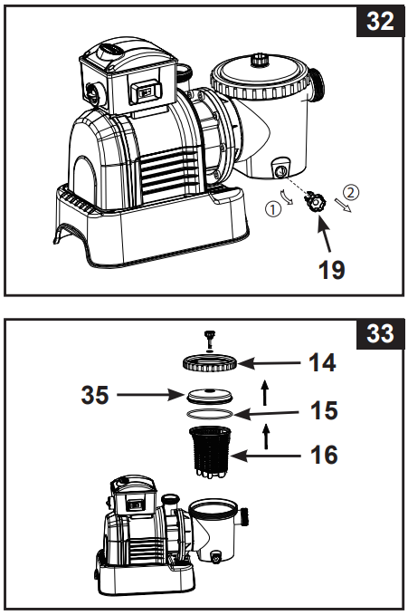
- Release the pressure first by opening the sediment release valve (19) located on the bottom side of the pre-filter housing (see figure 32).
In a counter-clockwise motion unscrew the leaf trap cover (14), then remove the basket (16) and leaf trap o-ring (15) from the pre-filter housing (see drawing 33).
- Empty and flush the basket using a garden hose, you can use a plastic brush to remove sediment from the basket. Do not use metal brushes.
- Clean and rinse the inside of the pre-filter container and leaf trap O-ring with a garden hose.
- Reinstall the leaf trap O-ring, basket and leaf trap cover into the pre-filter housing.
- Close the sediment release valve (19) again.
POOL CARE & CHEMICALS
- All pools require maintenance to keep their water clear and hygienic. With proper chemical control, your filter will help achieve this goal. Consult your pool supply dealer for instructions on the proper use of chlorine, algaecide, and other chemicals necessary for sparkling clear water.
- Keep pool chemicals away from children.
- Do not add chemicals to the pool while it is filling. Skin or eye irritation may occur.
- Daily pH checking and chemical maintenance of the water are essential and cannot be overemphasized. Chlorine, algaecide, and maintenance of proper pH levels are necessary when filling the pool as well as throughout the season. Consult your local pool supply store for instructions.
- The first filling of the pool season may have brackish water that requires additional water additions and additional filtration time. Do not allow swimming in the pool until the pH level is balanced. Consult your local pool supply store for instructions.
- Chlorinated water can damage grass, gardens, or shrubs when children play in the pool and splash water out of the pool. The grass area under the pond liner will be destroyed. Note that some types of grass can grow through the liner.
- Filter run times vary depending on pool size, weather, and usage levels. Experiment with different run times to produce clear, clean water.
CAUTION
Concentrated chlorine solutions can damage pool liners. Always follow chemical manufacturer's instructions, as well as health and hazard warnings.
LONG TERM STORAGE & WINTERIZATION
CAUTION
Allowing water to freeze will damage the sand filter and void the warranty. If an antifreeze solution is necessary, use only propylene glycol. Propylene glycol is non-toxic and will not damage plastic system components; other antifreezes are very toxic and can damage plastic components in the system.
- Before emptying your pool for long-term storage, or relocation, make sure the water is directed to an acceptable drain away from the house. Check local regulations for specific instructions regarding pool water disposal.
- Turn off the unit, and unplug the power cord from the wall outlet.
- When the pool is empty, disconnect all hoses from the pump and plunger valve and remove the strainer/plunger valve from the pool wall.
- In a counterclockwise motion, unscrew the drain valve (9) from the drain valve to drain the tank completely. The drain valve is located at the bottom of the filter tank.
- Remove the pump motor from the bottom of the tank.
- Leave the sand filter pump pieces and hose outside until completely dry.
- Coat the following o-rings and washers with petroleum jelly for long-term storage:
- L-shaped O-ring (11 & 18).
- Pump hose O-ring (22).
- Step washer filter valve assembly (23).
- Flat filter rubber washer (25).
- Press the 6-way valve handle and turn it to set the pointer to the top “N” position of the valve.
This allows water to flow from the valve. Leave the 6-way valve in this off position. - It is best to place all dry parts and pump motors in their original packaging for storage. To avoid condensation or corrosion problems, do not cover or wrap the pump motor with plastic bags.
- Store the pump motor and accessories in a dry place. The storage temperature should be controlled, between 0 degrees Celsius (32 degrees Fahrenheit) and 40 degrees Celsius (104 degrees Fahrenheit).
IMPORTANT SAFETY RULES
Read, Understand and Follow All Instructions Carefully Before Installing and Using this Product.
READ AND FOLLOW ALL INSTRUCTIONS
- To reduce the risk of injury, do not permit children to use this product. Always supervise children and those with disabilities.
- Children must stay away from this product and electrical cord(s).
- Assembly and disassembly by adults only.
- Risk of electric shock. Connect only to a grounding-type receptacle, this product is provided with a ground-fault circuit interrupter. If replacement of the plug or cord is needed, use only identical replacement parts.
- Always unplug this product from the electrical outlet before removing, cleaning, servicing or making any adjustment to the product.
- The unit is provided with a ground-fault circuit interrupter (GFCI). To test the GFCI, push the test button. The GFCI should interrupt power. Push the reset button, power should be restored. If the GFCI fails to operate in this manner. The GFCI is defective. If the GFCI interrupts power to the pump without the test button being pushed, a ground current is flowing, indicating the possibility of an electric shock. Do not use this pump. Disconnect the pump and have the problem corrected by a qualified service representative before using.
- Do not bury the electrical cord. Locate the cord where it will not be damaged by lawn mowers, hedge trimmers and other equipment.
- To reduce the risk of electric shock, replace damaged cord immediately. Use a qualified electrician to replace the cord.
- To reduce the risk of electric shock, do not use extension cords, timers, plug adaptors or converter plugs to connect unit to electric supply; provide a properly located outlet.
- Do not attempt to plug in or unplug this product while standing in water or when your hands are wet.
- Do not use an appliance leakage current interrupter (ALCI) in place of a GFCI since the ALCI will not protect people.
- Position this product away from pool, so as to prevent children from climbing on it and access the pool.
- Do not operate this product when pool is occupied.
- To reduce the risk of entrapment hazard, never enter the pool if suction strainer component is loose, broken, cracked, damaged or missing. Replace loose, broken, damaged, cracked or missing suction strainer components immediately.
- Never play or swim near suction fittings. Your body or hair may be trapped causing permanent injury or drowning.
- To prevent equipment damage and risk of injury, always turn pump off before changing the filter control valve position.
- Never operate this product above the maximum working pressure stated on the filter tank.
- Hazardous Pressure. Improper tank valve cover assembly could cause the valve cover to blow off and cause serious injury, property damage or death.
- This product is intended to be used only for the purposes described in the manual!
FAILURE TO FOLLOW THESE WARNINGS MAY RESULT IN PROPERTY DAMAGE, ELECTRIC SHOCK, ENTANGLEMENT OR OTHER SERIOUS INJURY OR DEATH.
CAUTION
This product is for use with storable pools only. Do not use with permanently-installed pools. A storable pool is constructed so that it is capable of being readily disassembled for storage and reassembled to its original integrity. A permanently-installed pool is constructed in or on the ground or in a building such that it cannot be readily disassembled for storage.
To reduce the risk of electric shock the pool must be installed no closer than 6 feet (1.8 m) from any electrical outlet. Do not place portable appliances closer than 5 feet (1.5 m) from the pool. These product warnings, instructions and safety rules provided with the product represent some common risks of water recreation devices and do not cover all instances of risk and danger. Please use common sense and good judgement when enjoying any water activity.
SAVE THESE INSTRUCTIONS
TROUBLESHOOTING GUIDE
TROUBLE | CAUSE | SOLUTION |
FILTER MOTOR FAILS TO START |
|
protected by a Class A Ground Fault Circuit Interrupter, or RCD.
|
FILTER DOESN’T CLEAN POOL |
|
|
FILTER DOESN’T PUMP WATER OR FLOW IS VERY SLOW |
|
|
PUMP DOESN’T WORK |
|
|
6-WAY VALVE/ COVER LEAKING |
|
|
HOSE LEAKING |
o-ring/L-shape o-ringmissing. |
|
TIMER IS INACCURATE OR TIMER CAN'TBE SET |
|
|
PRESSURE GAUGE DOESN’T WORK |
|
|
SAND IS FLOWING BACK INTO THE POOL |
|
|
INLET THREADED AIR CONNECTOR /AIR JET VALVE LEAKING |
|
|
COMMON POOL PROBLEMS
PROBLEM | DESCRIPTION | CAUSE | SOLUTION |
ALGAE |
|
|
|
COLORED WATER |
|
|
|
FLOATING MATTER IN WATER |
|
|
|
CHRONIC LOWWATER LEVEL |
|
|
|
SEDIMENT ON POOL BOTTOM |
|
|
|
SURFACE DEBRIS |
|
|
|
WARRANTY
Your Sand Filter Pump has been manufactured using high quality materials and workmanship. All Intex products are inspected and found to be free from defects before leaving the factory. This Limited Warranty applies only to the Sand Filter Pump and accessories listed below.
The terms of this Limited Warranty apply only to the original purchaser and are not transferable. This Limited Warranty is valid for the period stated below from the date of original retail purchase. Keep your original sales receipt with this manual, as proof of purchase will be required and must accompany any warranty claim or the Limited Warranty is void.
Sand Filter Pump Warranty – 2 Years
Hose, Plunger Valve & Fittings Warranty – 180 days
Pros & Cons
Pros
- Efficient Filtration: Effectively removes dirt and debris from the pool water.
- Durable Construction: Built with corrosion-resistant materials for long-lasting use.
- Easy Operation: Simple control valve and built-in timer for automated operation.
- Value for Money: Offers great performance at an affordable price.
Cons
- Noisy Operation: Some users have reported that the pump can be noisy during operation.
- Heavy Weight: The pump is quite heavy, making it difficult to move around.
- Complex Assembly: Some users find the assembly process challenging.
Customer Reviews
Customers have generally praised the Intex Sand Filter Pump SF80110-1 for its effective filtration and durable construction. Many reviewers have noted that it significantly improves the clarity of their pool water. However, some have mentioned that it can be noisy and heavy. Common complaints include issues with assembly and occasional leaks, but overall, the product is well-regarded for its performance.
Faqs
How should the Intex Sand Filter Pump SF80110-1 be configured?
For the Intex Sand Filter Pump SF80110-1, what kind of sand is suggested?
How often is the Intex Sand Filter Pump SF80110-1 supposed to be backwashed?
How can I fix the Intex Sand Filter Pump SF80110-1's poor water flow?
What is the Intex Sand Filter Pump SF80110-1's proper operating pressure?
How should the SF80110-1 Intex Sand Filter Pump be maintained?
How can I fix the Intex Sand Filter Pump SF80110-1's leaky pump?
What is the reason behind air bubbles in the Intex Sand Filter Pump SF80110-1's return jets?
Can heavy debris be handled by the Intex Sand Filter Pump SF80110-1?
How long is the Intex Sand Filter Pump SF80110-1 warranty?
Leave a Comment