Leviton Electronic Countdown Timer Switch LBT60 | Operating Instructions
Content
Introduction of Leviton Electronic Countdown Timer Switch LBT60
The Leviton Electronic Countdown Timer Switch LBT60 is a versatile and reliable timer switch that is perfect for a variety of applications. This countdown timer switch is designed to control lights, fans, and other electrical devices with ease. With its simple and user-friendly interface, you can set the timer to turn off your devices automatically after a specific amount of time has elapsed. The estimated price of the Leviton Electronic Countdown Timer Switch LBT60 is around $30 to $40, and it is already available in the market.
Leviton OOLS NEEDED TO INSTALL YOUR TIMER SWITCH
- Slotted/Phillips Screwdriver
- Electrical Tape
- Pliers
- Pencil
- Cutters
- Ruler
Changing the color of your device
Your device may include color options. To change color of the face, proceed as follows:

Color change kits available in White (W), Light Almond (T), Ivory (I), Brown (B), Black (E), (LTBKT-00x)
MAXIMUM LOAD PER TIMER FOR MULTI-DEVICE INSTALLATIONS
Resistive Load
Single: 20A (2400 W)
Two or more devices: 16A (1920 W)
Incandescent/Halogen Load
Single: 1800 W
Two or more devices: 1800 W
Inductive Load
Single: 20A
Two or more devices: 16A
Motor Load
Single: 1 HP
Two or more devices: 1 HP
LED/CFL Load
Single: 600 W
Two or more devices: 600 W
Detailed Specifications Timer Switch LBT60
The Leviton Electronic Countdown Timer Switch LBT60 has several key features that make it an excellent choice for anyone looking for a high-quality timer switch. Here are some of its specifications:
- Counts down from any time between 1 minute and 10 hours
- Single-pole, multi-location switch
- Backlit LCD screen for easy viewing
- Adjustable fade rate for smooth on and off transitions
- Patented preset buttons for quick and easy setting
- Manual override feature
- Suitable for indoor and outdoor use
- Rated for up to 15 amps
- Comes with a 5-year limited warranty
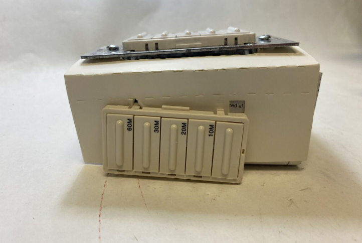
FEATURES OF YOUR COUNTDOWN TIMER SWITCH
- Four (4) Timer buttons and an OFF button.
- Each timer button has an adjacent green LED to indicate the current countdown time.
- The green bottom LED is ON when the load is OFF and is OFF when the load is ON.
- Your timer switch can be easily programmed to function as another model.
NOTE: LTB02, LTB04 and LTB12 are not programmable as a 2, 4, or 12- hour timer respectively, but can be programmed to function as any of the other timers.
INSTALLING YOUR TIMER SWITCH
WARNING: TO AVOID FIRE SHOCK OR DEATH; TURN OFF POWER at circuit breaker or fuse and test that power is off before wiring!
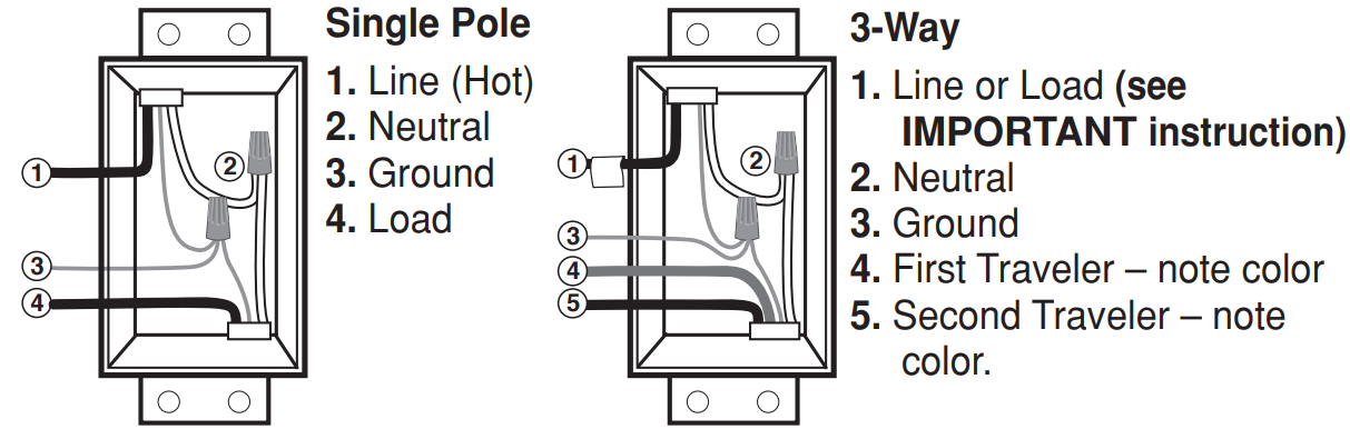
Identifying your wiring application (most common):
NOTE: If the wiring in your wallbox does not resemble any of these configurations, consult an electrician.
NOTE: For Wired Switch Companions (with LED) the First Traveler becomes Line Hot.
IMPORTANT: For 3-way applications, note that one of the screw terminals from the old switch being removed will usually be a different color (Black) or labeled Common. Tag that wire with electrical tape and identify as the common (Line or Load) in both the switch wallbox and Wired Switch Companion wallbox.
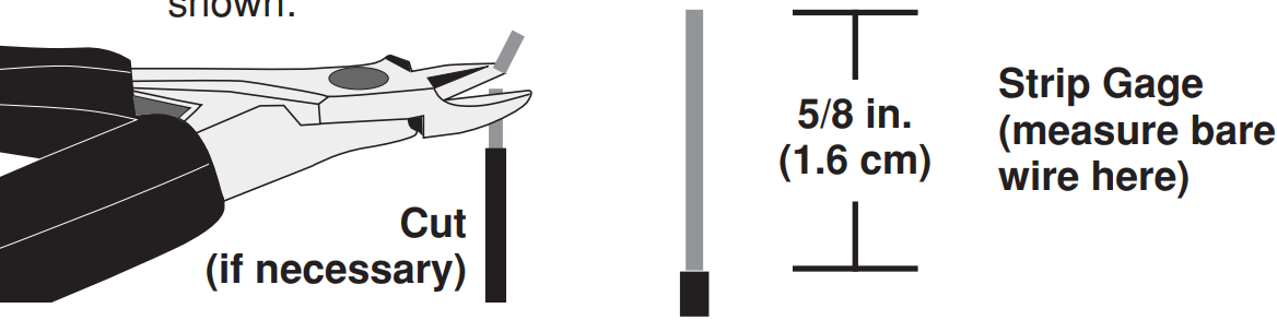
Preparing and connecting wires
Pull off pre-cut insulation from timer switch leads. Make sure that the ends of the wires from the wallbox are straight (cut if necessary). Remove insulation from each wire in the wallbox as shown
For non-standard wiring applications, refer to Wire Nut and Connector Size Chart
- Make sure that the ends of the wires from the wallbox are straight (cut if necessary).
- Remove insulation from each wire in the wallbox as shown.
- For single pole application, go to Step 4a.
- For 3-way Wired Switch Companion (without LED) application, go to Step 4b.
- For 3-Way Wired Switch Companion (with LED) application, go to Step 4c.
WIRE CONNECTOR / # OF COND. COMBINATION CHART
- 1 - #12 w/ 1 to 3 #14, #16 or #18
- 2 - #12 w/ 1 to 2 #16 or #18
- 1 - #14 w/ 1 to 4 #16 or #18
- 2 - #14 w/ 1 to 3 #16 or #18
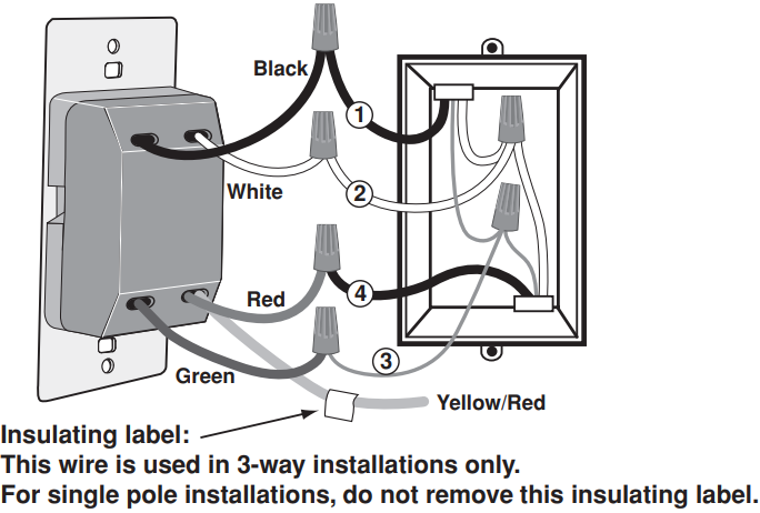
Single pole wiring application
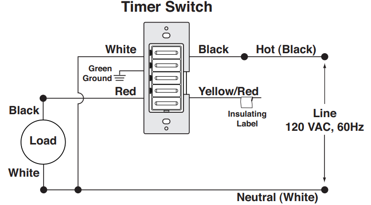
Leviton Electronic Countdown Wiring Timer Switch LBT60
Connect wires per WIRING DIAGRAM as follows:
- Green or bare copper wire in wallbox to Green lead.
- Line Hot wallbox wire to Black lead.
- Load wallbox wire to Red lead.
- Line Neutral wallbox wire to White lead.
- Timer Switch Yellow/Red lead should have Red insulation label affixed.
- Proceed to Step 5.
3-way wiring with Wired Switch Companion (VP0SR-10) application
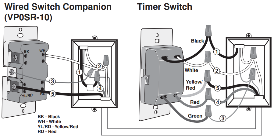

WIRING TIMER SWITCH
Connect wires per WIRING DIAGRAM as follows
NOTE: The timer switch must be installed in a wallbox that has a Line Hot connection.
NOTE: Maximum wire length from timer switch to all installed Wired Switch Companion devices cannot exceed 300 ft (90 m).
- Green or bare copper wire in wallbox to Green lead.
- Line Hot (common) wallbox wire identified (tagged) when removing old switch to Black lead.
- First Traveler wallbox wire to Red lead (note wire color).
- Remove Red insulating label from Yellow/Red lead.
- Second Traveler wallbox wire to Yellow/Red lead (note wire color). This traveler from the timer switch must go to the terminal screw on the Wired Switch Companion marked “YL/RD.”
- Line Neutral wallbox wire to White lead.
WIRING WIRED SWITCH COMPANION (VP0SR-10)
Connect wires per WIRING DIAGRAM as follows
NOTE: "BK" and "RD" terminals on Wired Switch Companion (VP0SR-10) are unused. Tighten both screws.
NOTE: Maximum wire length from timer switch to last Wired Switch Companion is 300 ft (90 m).
- Green or bare copper wire in wallbox to Green terminal screw.
- Load wallbox wire identified (tagged) when removing old switch to First Traveler (note color as above).
- Second Traveler wallbox wire (note color as above) to terminal screw marked "YL/RD." This traveler from the Wired Switch Companion must go to the Yellow/Red lead of the timer switch.
- Remove White insulating label from terminal screw marked “WH.”
- Line Neutral wallbox wire to terminal screw marked “WH.”
- Proceed to Step 5.
3-way wiring with Wired Switch Companions (VP0SR-1L) application
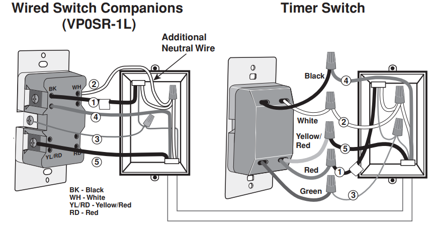
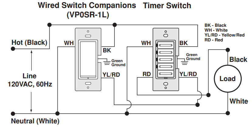
- NOTE: The timer switch must be installed in a wallbox that has a Load connection. The Wired Switch Companions (VP0SR-1L) must be installed in a wallbox with a Line Hot connection and a Neutral connection. A Neutral wire to the Wired Switch Companion (VP0SR-1L) needs to be added as shown. If you are unsure about any part of these instructions, consult an electrician.
NOTE: Maximum wire length from timer switch to all installed Wire Switch Companion devices cannot exceed 300 ft (90 m).
WIRING WIRED SWITCH COMPANIONS (VP0SR-1L)
(wallbox with Line Hot connection)
Connect wires per WIRING DIAGRAM as follows
- Green or bare copper wire in wallbox to Green terminal screw.
- Line Hot (common) wallbox wire identified (tagged) when removing old switch and First Traveler to wired switch companion screw marked “BK.”
- Second Traveler wallbox wire to wired switch companion terminal screw marked "YL/RD" (note wire color). This traveler from the wired switch companion must go to the Yellow/Red lead on the timer switch.
- Line Neutral wallbox wire to wired switch companion terminal screw marked “WH.”
WIRING TIMER SWITCH (wallbox with Load connection)
Connect wires per WIRING DIAGRAM as follows
- Green or bare copper wire in wallbox to Green lead.
- Load wallbox wire identified (tagged) when removing old switch to Red lead.
- First Traveler Line Hot to Black lead.
- Remove Red insulating label from Yellow/Red lead.
- Second Traveler wallbox wire (note color as above) to Yellow/Red lead. This traveler from the timer switch must go to the terminal screw on the wired switch companion marked “YL/RD.”
- Line Neutral wallbox wire to White lead.
- Proceed to Step 5.
Testing your Timer Switch prior to mounting in wallbox
- Position all wires to provide room in outlet wallbox for device.
Ensure that the word “TOP” is facing up on device strap.
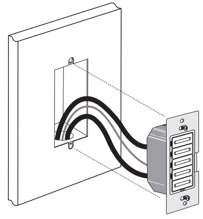
Partially screw in mounting screws in wallbox mounting holes.
NOTE: Dress wires with a bend as shown in diagram in order to relieve stress when mounting device.- Restore power at circuit breaker or fuse.
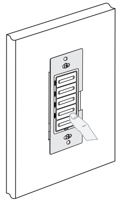
Press any timer button to turn the load ON. If the load does not turn ON, refer to the TROUBLESHOOTING section.
Timer Switch mounting
TURN OFF POWER AT CIRCUIT BREAKER OR FUSE.
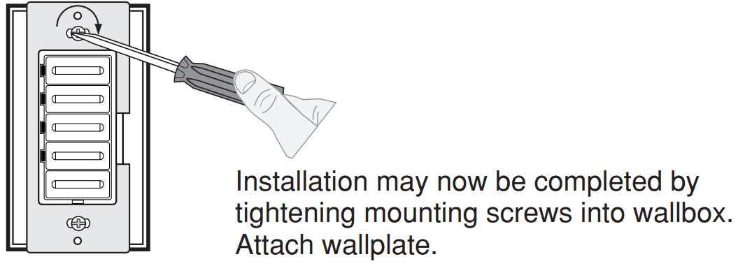
Restore power: Restore power at circuit breaker or fuse. Installation is complete.
Leviton Electronic Countdown Timer Switch Operation
- To turn the load ON press one of the timer buttons. The green LED adjacent to that button will illuminate and the timer will begin to countdown for the selected timer period.
- To select a different countdown time press the button corresponding to the desired time. The LED adjacent to that button will illuminate and the timer will begin countdown from the new selection.
- To turn the load OFF press the OFF button or wait until the selected amount of time has passed. The LED adjacent to each button will extinguish as time passes to the next preset level.
Timer override
To override the Timer countdown press and hold the top button for several seconds. The locator LED will turn amber to indicate the EXTENDED ON state. In this state the timer will automatically turn OFF after 24 hours. To exit the EXTENDED ON state press any of the timer buttons or the OFF switch.
ADVANCED PROGRAMMING FEATURE
| Timer Switch Number | Buttons | Time outs |
|---|---|---|
| LTB02 | 1 (top timer button) | 15m, 30m, 1hr, 2hr |
| LTB04 (special order only) | 1 (top timer button) | 30m, 1hr, 2hr, 4hr |
| LTB12 | 1 (top timer button) | 2, 4, 8, 12 hours |
| LTB60 | 2 | 10, 20, 30, 60 minutes |
| LTB30 | 3 | 5, 10, 15, 30 minutes |
| LTB15 | 4 (bottom timer button) | 2, 5, 10, 15 minutes |
| N/A | 5 - OFF button | N/A |
Timer Select Mode
You can change the time outs on your timer without buying a new device. Your timer can be programmed to function as any of the timers in the table below:
NOTE: If you change the ON times of your timer the printed face will no longer match the ON times. A timer change kit should be purchased to alleviate this situation.
To select different ON times please follow the subsequent steps
- Press and hold the first and third timer buttons simultaneously to enter Select Timer Mode.
- The timer’s indicator LED will turn AMBER. Continue to hold until the indicator LED and the current selected mode start flashing GREEN.
- Press button (from the table above) that corresponds with the time outs you desire and it will then start flashing GREEN.
- Pressing OFF will save programming, exit Programming Mode, and turn timer off.
NOTE: The timer will also exit Programming Mode automatically if no buttons are pressed for 3 minutes.
Multi Location Control
The Timer can be turned ON or OFF from any of the Decora Wired Switch Companion locations. The default ON time when a wired switch companion is pressed to turn the load ON will be the last countdown time chosen. The timer can be controlled from up to 10 locations using wired switch companion (VP0SR-10) or up to 5 locations using wired switch companions (VP0SR-1L).
Description of Leviton Electronic Countdown Timer Switch LBT60
The Leviton Electronic Countdown Timer Switch LBT60 is a versatile and easy-to-use timer switch that can control a wide variety of devices. It is perfect for use in homes, offices, and other commercial spaces. With its simple interface, you can quickly and easily set the timer to turn off your devices automatically. The backlit LCD screen makes it easy to view the time settings, even in low light conditions. The adjustable fade rate feature ensures smooth on and off transitions, while the manual override feature allows you to override the timer setting manually.
Troubleshooting
- Intermittent operation
- Load has a bad connection.
- Wires are not secured firmly to leads of timer switch and terminals of the Wired Switch Companion.
- Load does not turn ON and Locator LED does not turn ON
- Circuit breaker or fuse has tripped.
- Load is burned out.
- Neutral connection is not wired.
- Wired Switch Companion does not operate load
- Ensure that total wire length does not exceed 300 ft (90 m).
- Ensure that a Neutral wire is used with Wired Switch Companion.
NOTE: Sharing a Neutral wire may cause improper operation. Connect all timers to the same phase or run a separate Neutral to each phase.
Leviton Warranty
For Leviton’s limited 5 year product warranty, go to https://leviton.com/
Pros & Cons
Pros
- Easy to use with a simple interface
- Backlit LCD screen for easy viewing
- Adjustable fade rate for smooth transitions
- Manual override feature
- Can be used for indoor and outdoor applications
Cons
- May be challenging to program for some users
- Some users may prefer a digital display instead of an analog display
Customer Reviews about Timer Switch LBT60
Customers who have purchased and used the Leviton Electronic Countdown Timer Switch LBT60 have generally given it positive reviews. Many users appreciate its ease of use and versatility. Some users have noted that the timer can be challenging to program initially, but once set, it works well. The most common complaint among customers is that the timer switch can be a bit bulky and may not fit in some standard switch boxes.
Faqs
How do I install my Leviton Electronic Countdown Timer Switch LBT60?
What type of lighting can I control with the Leviton Electronic Countdown Timer Switch LBT60?
How do I program the countdown times on my Leviton Electronic Countdown Timer Switch LBT60?
What are the steps for maintaining my Leviton Electronic Countdown Timer Switch LBT60?
Can the Leviton Electronic Countdown Timer Switch LBT60 be used to control fans or motors?
How do I reset the Leviton Leviton Electronic Countdown Timer Switch LBT60 to factory settings?
Is the Leviton Leviton Electronic Countdown Timer Switch LBT60 suitable for outdoor use?
How energy-efficient is the Leviton Electronic Countdown Timer Switch LBT60?
Can I use the Leviton Electronic Countdown Timer Switch LBT60 with dimmable lights?
What is the warranty period for the Leviton Electronic Countdown Timer Switch LBT60?
Leave a Comment