Lippert JT's Strong Jack Arm Stabilizer Kit Owner Manual
Content
Introduction of JT's Strong Jack Arm Stabilizer Kit
The JT Strong Arm Stabilizer System is a locking bracket system used to stabilize and eliminate chassis movement in travel trailers and 5th Wheels using a triangulation system attached to the coach’s landing gear or jacks and frame. The JT StrongArm Stabilizer system is intended to eliminate chassis movement in travel trailers and 5th Wheels. It should not be used for any other purpose. With an estimated price range of $150 to $200 and a launching date set for early 2023, now is the perfect time to invest in this top-of-the-line stabilizer kit.
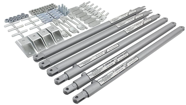
Parts List
P/N 191023 - Jack Stabilizer, 5th Wheel - 58” or more between front jacks
P/N 191024 - Jack Stabilizer, 5th Wheel, Short - Less than 58” between front jacks
JT's Resources Required
- Tape measure
- Felt-tip black marker
- Hammer
- Center punch
- Electric or cordless drill or screw gun
- 1/8” drill bit (for pilot holes)
- 5/16” drill bit
- 3/8” drill bit
- 1/2” “Uni-bit,” or step bit, preferred—standard 1/2” drill bit acceptable
- Countersink bit (for deburring)
- 9/16” deep socket and ratchet
- 9/16” box end wrench
- 5/8” box end wrench
- 11/16” box end wrench
- Locking pliers
- 3”-4” C-Clamp
- White grease
- Safety glasses
- Face shield
- Squeegee
Preparation
- Make sure to park the trailer on solid, level ground.
- Clear all jack landing locations of debris and obstructions.
- Locations should be free of depressions.
- When parking trailer on extremely soft surfaces, utilize load distribution pads under each jack.
- People and pets should be clear of trailer while operating leveling system.
Lippert JT's Strong Jack Arm Stabilizer Kit Installation
- For 2006 or later telescoping jacks:
- Replace existing 3/8” jack pad bolt with 3/8” - 16 x 4” swing bolt.
- Use 3/8” - 16 nut to secure. Insert a 3/8” - 16 x 1 1/4” swing bolt with the tab pointing to the rear of the chassis.
- Secure with a 3/8” washer and 3/8” - 16 Nyloc nut.
- Prepare T-Bolts and stabilizer tubes as described in step 12, except the inner tube should be set at 1” instead of 5”.
- After fully retracting rear telescoping jacks, attach the clevis end of the stabilizer inner tube to the swing bolt tab on the rear side of the jack using a 3/8” - 16 x 1 1/2” bolt with a 3/8” washer on the top and bottom of the tab and a 3/8” - 16 Nyloc nut.
- Tighten nut until tight.
- Repeat steps 1A-1F on opposite side.
- Locate a cross-member rearward of the rear jacks at a minimum of 6” to a maximum of 18”.
- Under front half of chassis, locate a cross-member or center compartment with a steel floor from 6”-18” from front of electric leveling jacks.
NOTE: If unable to locate a suitable mounting location at the front or rear of chassis, contact LCI customer service.
- Under front half of chassis, locate a cross-member or center compartment with a steel floor from 6”-18” from front of electric leveling jacks.
- At the front of the chassis, measure the inside distance between the front electric leveling jacks just below the frame of the chassis.
- If measurement between front electric jacks is 58” to 66” and the chassis is insulated and has a center compartment with a steel floor located between the front jacks, refer to step 4.
- If measurement between the front jacks is 58” to 66” and the chassis is uninsulated with a C-Channel cross-member, refer to step 5.
- If the measurement between the front jacks is 66” or longer and the chassis is uninsulated with a C-Channel cross-member, refer to step 6.
- If the measurement between the front jacks is 66” or longer and the chassis is insulated and has a center compartment with a steel floor located between the front jacks, refer to step 7.
- If the measurement between the front jacks is 66” or longer and the chassis is insulated and the cross-member is constructed of tubular steel, refer to step 4.
- If the measurement between the front jacks is less than 58”, use kit #191024.
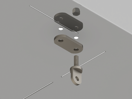
- Mark the bottom of the center compartment centered between the front electric jacks. Mark the center of one of the stiffening pads between the mounting holes.
- Align the center marks on the stiffening pad and the bottom of the center compartment and place the stiffening pad 1/4” from the front edge of the center compartment.
- Mark the center of each mounting hole in the stiffening pad on the bottom of the center compartment and centerpunch the marks.
CAUTON: REMOVE PERSONAL PROPERTY AND VALUABLES FROM THE CENTER COMPARTMENT TO PREVENT POSSIBLE DAMAGE OCCURING DURING DRILLING. - To prevent accidental damage to personal property, clear the center compartment of any valuables.
- Drill a 1/8” pilot hole at each mounting hole location.
- Drill 3/8” mounting holes. Use a countersink bit to deburr the inside of the holes.
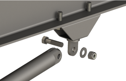
- Sandwich the floor of the center compartment between two stiffening pads.
- Insert two 3/8” - 16 x 1 1/4” swing bolts, two 3/8” SAE flat washers and two 3/8” - 16 Nyloc nuts.
Tighten nuts enough to ensure needing a screwdriver for leverage to pivot swing bolts.
- Mark the bottom of the cross-member centered between the front electric jacks. Mark the center of one of the stiffening pads between the mounting holes.
- Align the center marks on the stiffening pad and the bottom of the cross-member, clamp pads with a pair of locking pliers or C-Clamps.
- Drill 3/8” mounting holes. Use a countersink bit to deburr inside of holes.
- Sandwich the floor of the center compartment between two stiffening pads.
- Insert two 3/8” - 16 x 1 1/4” swing bolts, two 3/8” SAE flat washers and two 3/8” - 16 Nyloc nuts
- Tighten nuts enough to ensure needing a screwdriver for leverage to pivot swing bolts (Fig.1).
- From the inside of both front jacks, measure toward the center of the cross-member 30” and place a mark. Mark the center of two of the stiffening pads between the mounting holes.
- Align the center marks on the stiffening pad and the bottom of the cross-member and clamp with a pair of locking pliers or C-Clamp.
- Drill the mounting holes with a 3/8” bit.
- Secure the stiffening pads to the bot-tom of the cross-member with two 3/8” x 1 1/4” swing-bolts (P/N 191010), two 3/8” x 1 1/2” bolt (P/N 155004), four 3/8” washers (P/N 135840), and four 3/8”-16 locking nuts (P/N 118044).
NOTE: The swing bolts should be inserted into the mounting holes located closest to the electric jacks.- Tighten nuts enough to ensure needing a screwdriver for leverage to pivot swing bolts (Fig.1).
- From the inside of both front jacks, measure toward the center of the center compartment 30” and place a 2” mark 1/4” from the front edge of the compartment.
- Mark the center of two of the stiffening pads between the mounting holes.
- Align the center marks on the stiffening pads and the bottom of the center compartment and place the stiffening pad 1/4” from the front edge of the compartment.
- Mark the center of each mounting hole in the stiffening pads on the bottom of the center compartment, then centerpunch the marks.
CAUTION: REMOVE PERSONAL PROPERTY AND VALUABLES FROM THE CENTER COMPARTMENT TO PREVENT POSSIBLE DAMAGE OCURRING DURING DRILLING. - To prevent accidental damage to personal property, clear the center compartment of any valuables.
- Drill a 1/8” pilot hole at each mounting hole location. Drill 3/8” mounting holes. Use a countersink bit to deburr the inside of the holes.
- Sandwich the floor of the center compartment between the stiffening pads.
- Secure the pads using two 3/8” - 16 x 1 1/4” swing bolts, two 3/8” x 1 1/2” bolts, four 3/8” washers and four 3/8” - 16 locking nuts.
- The swing bolts should be inserted into the mounting holes located closest to the electric jacks.
- Tighten nuts enough to ensure needing a screwdriver for leverage to pivot swing bolts.
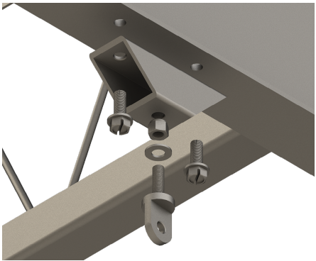
- Insert a 3/8” - 16 x 1 1/4” swing bolt into a spacer mount and secure with a 3/8” washer and 3/8” - 16 Nyloc nut.
- From the inside of both front jacks, measure toward the center of the cross-member 27 3/4” and place a mark. Align one of the short edges of the spacer mount with the mark keeping the swing bolt toward the center of the chassis.
- Mark the center of the mounting holes, then centerpunch them.
- Drill 1/8” pilot holes at the four mounting hole locations, then re-drill the holes located closest to the electric jacks to 5/16” on both sides of chassis.
- Tap the 5/16” holes with either a 3/8” - 16 tap or a 3/8” -16 x 1” self-tapping bolt. Lubricate tap as needed.
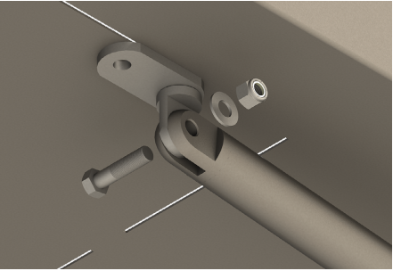
- Remove tap or bolt and secure spacer mount with a 3/8” - 16 x 1” self-tapping bolt, taking care to keep the remaining pilot hole centered in the mounting hole of the spacer mount. Tighten bolt securely.
Drill remaining pilot hole to 5/16” and insert a 3/8” - 16 x 1” self-tapping bolt and tighten (Fig.2).
- Repeat steps 8A-8F on opposite side of chassis.
- Make sure the adjustment holes in each jack leg above the foot pad pin are 1/2” diameter. If not, re-drill hole with a step bit or standard 1/2” bit, then deburr holes with a countersink bit.
- Insert a 3/8” I.D. x 1/2” O.D. flanged bushing into the second from the bottom holes in each jack leg.
- Apply a thin layer of white grease to the shaft of a 3/8” - 16 x 4” swing bolt and the flanges of the bushings.
- For each jack leg, do as follows:
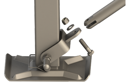
- Align the mounting holes of the electric jack clevis with the bushings from the rear of the jack leg and insert the swing bolt through both sides with the shoulder and 3/8” washer on the inside of the jack leg.
- Apply a thin layer of grease to a 3/8” washer and place on outside of clevis, over the swing bolt.
- Secure the swing bolt and clevis with a 3/8” - 16 grade A heavy hex nut.
Tighten heavy hex nut enough to eliminate side play (Fig.3).
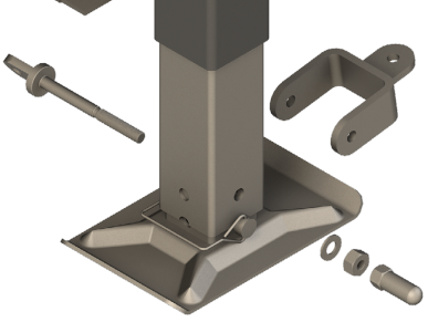
- Thread a 3/8“ - 16 nut (“Silver Bullet”) lifting handle onto the outside of the swing bolt. Tighten nut lifting handle against the 3/8” - 16 heavy hex nut (Fig.3).
NOTE: For chassis that are constructed with “I” or “H” beam main rails (front-to-back) and are uninsulated, go to step 10. For chassis that are constructed with “I” or “H” beam main rails or tubular frames and/or insulated, go to step 12.
- From the rear side of an electric jack leg, measure 30” and place a mark on the bottom of each main rail. Measure the bottom flange of each main rail, then divide that measurement by four to determine the center location of the mounting hole.
- Centerpunch the intersection of the lines, then drill a 1/8” pilot hole.
- Re-drill out the pilot hole to 3/8” and deburr with a countersink bit.
- Secure a stiffening pad to the bottom of the main rail flange using a 3/8” - 16 x 1 1/4” swing bolt, a 3/8” washer and a 3/8” - 16 Nyloc nut.
NOTE: The edge of the stiffening pad should be parallel to the edge of the main rail flange. Drill remaining mounting hole and secure with a 3/8” - 16 x 1 1/2” bolt, 3/8” washer and 3/8” - 16 Nyloc nut (Fig.4).
- Repeat steps 10A-10D for opposite side of the chassis.
- Measure from the rear side of the electric jack leg 27 3/4” and place a mark on the bottom of the main rails. Assemble a spacer mount.
- Using the spacer mount as a template, mark the mounting holes by aligning one short edge with the 27 3/4” mark.
NOTE: The spacer mount should be parallel to the outside of the main rail flange. - Center punch and drill 1/8” pilot holes at each mounting hole location.
- Re-drill the holes located closest to the front jacks to 5/16” on both sides of the chassis.
- Tap the 5/16” holes with either a 3/8” - 16 tap or a 3/8” -16 x 1” self-tapping bolt. Lubricate tap as needed.
- Secure spacer mount to bottom of main rail flange with a 3/8” - 16 x 1” self-tapping bolt, taking care to keep the remaining pilot hole centered in the mounting of the spacer mount. Tighten bolt securely.
Re-drill the remaining pilot hole to 5/16”. Then insert a 3/8” - 16 x 1” self-tapping bolt and tighten.
- Repeat steps 11A-11F for opposite side of the chassis.
- Using the spacer mount as a template, mark the mounting holes by aligning one short edge with the 27 3/4” mark.
- Apply white grease to the threads of two T-Bolts, then partially thread them into the top holes of the outer stabilizer tubes.
- Remove inner stabilizer tube from assembly and discard the plastic shipping bag.
Reassemble stabilizer tubes with the inner tube sticking out past the end of the outer tube by 5”. Tighten T-Bolts until snug (Fig.6).
- To ensure proper installation, make sure the warning labels are facing outward and right-side up. The T-Bolts should be on the top side of the stabilizers.
- Apply a thin layer of white grease to swing bolt tabs.
- Attach clevis of outer stabilizer tube to the swing bolt tab under center of chassis with a 3/8” - 16 x 1 1/2” bolt, 3/8” washer and 3/8” - 16 Nyloc nut.
- Tighten nut until the stabilizer tubes swing to the ground with resistance.
- Attach clevis of inner stabilizer tube to swing bolt tab on jack leg with a 3/8” - 16 x 1 1/2” bolt, 3/8 washer and 3/8” - 16 Nyloc nut. Loosen T-Bolt if needed.
- Repeat steps 13A-13D for opposite side of the chassis.
- Prepare stabilizer tube as described in step 12. To ensure proper installation, make sure the warning labels are facing outward and right-side up. The T-Bolts should also be on the top side of the stabilizers.
- Apply a thin layer of white grease to swing bolt tabs.
- Attach clevis of outer stabilizer tube to the swing bolt tab under main rail of chassis with a 3/8” - 16 x 1 1/2” bolt, 3/8” washer and 3/8” - 16 Nyloc nut.
- Tighten nut until the stabilizer tubes swing to the ground with resistance.
- Attach clevis of inner stabilizer tube to tab on electric jack clevis with a 3/8” - 16 x 1 1/2” bolt, 3/8 washer and 3/8” - 16 Nyloc nut. Loosen T-Bolt if needed.
- Repeat steps 14A-14D for opposite side of the chassis.
NOTE: For chassis with rear scissor jacks, go to step 15. For chassis with telescoping rear jacks, go to step 16.
- Starting with one of the rear scissor jacks, remove the existing lower, outside pivot bolt. Replace pivot bolt with a 3/8” - 16 x 4” swing bolt.
- Install swing bolt from back-to-front with the shoulder of the swing bolt to the rear side of the jack.
- Place 3/8” washer and a 3/8” - 16 Nyloc nut onto the threaded end of the swing bolt. Tighten nut enough so that the swing bolt will only pivot by using a screwdriver for leverage. Make sure the swing bolt tab is positioned horizontally.
- Prepare T-Bolts and stabilizer tubes as described in step 12, except the inner tube should be set at 1” instead of 5”.
- After fully retracting rear scissor jacks, attach the clevis end of the stabilizer inner tube to the swing bolt tab on the rear side of the jack using a 3/8” - 16 x 1 1/2” bolt with a 3/8” washer on the top and bottom of the tab and a 3/8” -16 Nyloc nut. Tighten nut until tight.
- Repeat steps 15A-15D for opposite side of the chassis.
NOTE: If scissor jacks are less than 2” wide, washers will be necessary on the swing bolt because the threads may not be long enough.
- Drill a 3/8” hole centered in the telescoping channel and 1” up from the end.
- For 2006 or later telescoping jacks:
- Replace existing 3/8” jack pad bolt with 3/8” - 16 x 4” swing bolt. Use 3/8” - 16 nut to secure swing bolt.
- Insert a 3/8” - 16 x 1 1/4” swing bolt with the tab pointing to the rear of the chassis. Secure with a 3/8” washer and 3/8” - 16 Nyloc nut. Tighten as described in step 10.
- Prepare T-Bolts and stabilizer tubes as described in step 12, except the inner tube should be set at 1” instead of 5”.
- After fully retracting rear telescoping jacks, attach the clevis end of the stabilizer inner tube to the swing bolt tab on the rear side of the jack using a 3/8” - 16 x 1 1/2” bolt with a 3/8” washer on the top and bottom of the tab and a 3/8” - 16 Nyloc nut. Tighten nut until tight.
- Repeat steps 16A.I-16A.IV for opposite side of the chassis.
- For chassis that are constructed with C-Channel rear cross-members and uninsulated, go to step 17.
- For chassis that are constructed with C-Channel rear cross-members or tubular frames and/or insulated, refer to step 18.
- For 2006 or later telescoping jacks:
- Attach a 3/8” - 16 x 1 1/4” swing bolt to the clevis end of the stabilizer outer tube with a 3/8” - 16 Nyloc nut and 3/8” washer. Tighten nut enough to allow swing bolt to point upwards.
- Rotate stabilizer tube toward center of chassis and up to cross-member identified in step 2.
- Mark where center of swing bolt meets the center of the cross-member front-to-back on the bottom of the cross-member.
- Align a stiffening pad with the outer hole centered on the mark for the center of the swing bolt. Clamp the stiffening pad to the cross-member with a pair of locking pliers and drill mounting holes with a 3/8” bit.
- Secure stiffening pad to the cross-member with a 3/8” - 16 x 1 1/4” bolt, 3/8” - 16 Nyloc nut and 3/8” washer in the inside mounting hole.
- After removing the locking pliers, attach swing bolt to remaining mounting hole with a 3/8” - 16 Nyloc nut and washer.
- Repeat steps 17A-17E for opposite side of the chassis.
- Prepare spacer mounts as described in step 8. Rotate stabilizer tubes toward center of chassis and upward to cross-member identified in step 2.
- Using the spacer mount as a template, mark the mounting holes by aligning one short edge with the center of the cross-member. Make sure the spacer mount is parallel to the edge of the rear cross-member.
- Center punch and drill 1/8” pilot holes at each mounting hole location.
- Drill 1/8” pilot holes at the four mounting hole locations, then re-drill the holes located closest to the electric jacks to 5/16” on both sides of chassis.
- Tap the 5/16” holes with either a 3/8” - 16 tap or a 3/8” -16 x 1” self-tapping bolt. Lubricate tap as needed.
- Secure spacer mount to bottom of rear cross-member with a 3/8” - 16 x 1” self-tapping bolt, taking care to keep the remaining pilot hole centered in the mounting of the spacer mount. Tighten bolt securely.
- Re-drill the remaining pilot hole to 5/16”. Then insert a 3/8” - 16 x 1” self-tapping bolt and tighten.
- Repeat steps 18A-18F for opposite side of chassis.
- Place Warning Label in any available location that is visible while operating electric leveling jack switch.
- Clean mounting surface thoroughly.
- Remove backing from label and adhere to mounting surface using a squeegee or similar tool.
Operation
- Level your trailer side-to-side.
- Lower the front of the trailer 3/4” lower than the rear.
- Lower and set rear jacks evenly.
- Tighten the T-Bolts on the two rear Strong Arm Jack Stabilizers.
- Raise the front of the trailer to make it level front- to-back.
- Tighten T-Bolts on the four front Strong Arm Jack Stabilizers.
- Briefly press the electric jack switch so the jacks slightly lift the front of the trailer. This eliminates the play (movement) at the bolts and bolt holes between the stabilizers and the trailer.
Maintenance
Periodically wash the strong arms with water to remove any salt or debris. Then wipe dry with a clean, dry cloth.
Detailed Specifications
Lippert JT's Strong Jack Arm Stabilizer Kit is built to last, with the following key features:
- Constructed from high-strength steel for maximum durability
- Features a unique linkage design for added stability
- Easy-to-install brackets and hardware included
- Designed for use with Lippert JT's Super Slide Out and other leading slide-out systems
- Rugged powder coat finish for added protection against the elements
Description of Lippert JT's Strong Jack Arm Stabilizer Kit
Lippert JT's Strong Jack Arm Stabilizer Kit is a premium stabilizer system that is designed to provide maximum support for your trailer's jack arms. The kit includes all necessary hardware and easy-to-install brackets, making it a breeze to set up and start using right away. With its unique linkage design, this stabilizer kit significantly reduces any swaying or rocking motion that can occur when you're on the road, providing added peace of mind and a safer, more secure camping experience. The rugged powder coat finish ensures that the kit can withstand even the toughest conditions, making it a reliable choice for RVers who demand the best.
JT's Strong Jack Arm Setup Guide
Setting up Lippert JT's Strong Jack Arm Stabilizer Kit is easy, with just a few simple steps:
- Identify the location where the stabilizer kit will be installed on your trailer's jack arm
- Attach the brackets to the jack arm using the included hardware
- Connect the linkage to the brackets and the jack arm
- Test the stabilizer kit by applying weight to the trailer and observing the motion of the jack arm
Read and fully understand all instructions within this manual and adhere to all safety labels.
- WARNING: FAILURE TO ACT IN ACCORDANCE WITH THE FOLLOWING MAY RESULT IN DEATH, SERIOUS PERSONAL INJURY OR SEVERE PRODUCT OR PROPERTY DAMAGE.
- WARNING: NEVER LIFT THE UNIT COMPLETELY OFF THE GROUND. LIFTING THE UNIT SO THE WHEELS ARE NOT TOUCHING THE GROUND WILL CREATE AN UNSTABLE AND UNSAFE CONDITION.
- WARNING: THE TRAILER MUST BE SUPPORTED PER THE MANUFACTURER’S RECOMMENDATIONS BEFORE WORKING UNDERNEATH. FAILURE TO DO SO MAY RESULT IN DEATH, SERIOUS PERSONAL INJURY OR SEVERE PRODUCT OR PROPERTY DAMAGE.
- WARNING: WHEN USED WITH AN AUTOMATIC LEVELING SYSTEM, STRONG ARMS MUST BE UNLOCKED BEFORE RETRACTING THE JACKS. FAILURE TO DO THIS MAY RESULT IN SERIOUS PERSONAL INJURY OR SEVERE PRODUCT OR PROPERTY DAMAGE.
- CAUTION: LWAYS WEAR EYE PROTECTION WHEN PERFORMING SERVICE OR MAINTENANCE TO THE TRAILER. OTHER SAFETY EQUIPMENT TO CONSIDER WOULD BE HEARING PROTECTION, GLOVES AND POSSIBLY A FULL FACE SHIELD, DEPENDING ON THE NATURE OF THE SERVICE.
- CAUTION: MOVING PARTS CAN PINCH, CRUSH OR CUT. KEEP CLEAR AND USE CAUTION.
Lippert JT's Strong Jack Arm Stabilizer Kit Troubleshooting
If you experience any issues with Lippert JT's Strong Jack Arm Stabilizer Kit, here are some common problems and solutions to consider:
- If the stabilizer kit is not providing the expected level of stability, check the installation to ensure that it is secure and properly aligned.
- If the linkage is binding or not moving freely, check for any debris or obstructions that may be restricting the movement.
- If the powder coat finish is showing signs of wear or damage, consider applying a touch-up coat of paint to protect against further wear.
Pros & Cons
Pros
- Provides maximum stability for your trailer's jack arms
- Easy to install and use
- Constructed from high-strength steel for added durability
- Features a unique linkage design for added stability
- Rugged powder coat finish provides added protection against the elements
Cons
- May not be compatible with all trailer brands or models
- May require additional modifications to work with certain slide-out systems
- Slightly more expensive than some competing stabilizer kits
Customer Reviews about Lippert JT's Strong Jack Arm Stabilizer Kit
"I've been using Lippert JT's Strong Jack Arm Stabilizer Kit on my trailer for several months now, and I can honestly say that it has been a game-changer. The kit is incredibly easy to install and provides a level of stability that I've never experienced before. I highly recommend it to any RVer who wants to ensure their trailer remains secure and safe on the road." - John D.
"I was a little skeptical about the price of Lippert JT's Strong Jack Arm Stabilizer Kit at first, but after using it for a few trips, I can say that it's been worth every penny. The kit is well-made, easy to install, and provides a level of stability that I didn't know was possible. I'm thrilled with my purchase and would recommend it to anyone who wants to take their camping experience to the next level." - Sarah L.
Faqs
What is the purpose of Lippert JT's Strong Jack Arm Stabilizer Kit?
How does Lippert JT's Strong Jack Arm Stabilizer Kit work?
Is the Lippert JT's Strong Jack Arm Stabilizer Kit universal?
Does the Lippert JT's Strong Jack Arm Stabilizer Kit include everything needed for installation?
Is the Lippert JT's Strong Jack Arm Stabilizer Kit adjustable for different RV heights?
How do the Lippert JT's Strong Jack Arm Stabilizer Kit engage and disengage?
Are there any models of RVs for which Lippert JT's Strong Jack Arm Stabilizer Kit is not suitable?
How do I know if the Lippert JT's Strong Jack Arm Stabilizer Kit is properly engaged?
What is the life expectancy of the Lippert JT's Strong Jack Arm Stabilizer Kit?
If a component of the Lippert JT's Strong Jack Arm Stabilizer Kit becomes damaged, can I purchase individual replacement parts?
Leave a Comment