Motekind Digital Measuring Machine HD8645 User Guide
Content
Introduction
The Saeco Automatic Espresso Machine HD8645 is a high-performance appliance designed for coffee enthusiasts. It features a built-in grinder with 10 adjustable settings, allowing you to customize the grind size to suit your taste. The machine also offers pre-brewing and a 15-bar pressure pump for optimal extraction. With its sleek design and intuitive control panel, the Saeco HD8645 delivers consistently delicious espresso drinks. The price of the Saeco Automatic Espresso Machine HD8645 is $499.99.
Component Identification
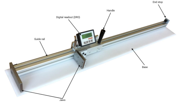
Note: DRO is powered by (1) C battery and will not power off. The battery will need to be replaced approximately every 9-12 months depending on use and battery capacity. An industrial grade battery is recommended for maximum battery life.
Technical Specifications
- Resolution 0.001”, 0.01mm, 1/64”
- Accuracy ±0.001” per foot of measure
- Repeat accuracy ±0.001”
- Operating temperature range 32°-122°F
- Protection level IP60 DRO (front) IP67 scale
- Max measuring speed 16 feet per second
- Power supply (1) C battery
- Jaw size 3.375” x 2.50”
This DMM has been tested by Motek Industries to meet or exceed the performance specifications listed above in accordance with length measuring equipment traceable to master standards at the National Institute of Standards and Technology (NIST). The specific calibration sheet for this DMM has been inserted as the final page in this manual for your records.
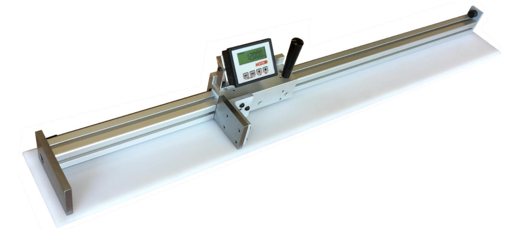
Description
The motekind Digital Measuring Machine is a versatile and easy-to-use tool that provides quick and accurate measurements. It features a large LCD screen with backlight for easy reading, even in low light conditions. The measuring range is from 0-150mm/0-6 inches, with an accuracy of ±0.02mm/±0.001 inches and a resolution of 0.01mm/0.0005 inches. The device is powered by four AA batteries or a USB power supply, and it comes with a handy storage case. The motekind Digital Measuring Machine is compact and lightweight, making it easy to carry around in your toolbox or pocket.
Saeco Automatic Espresso Machine HD8645 DRO Operation
DRO button identification
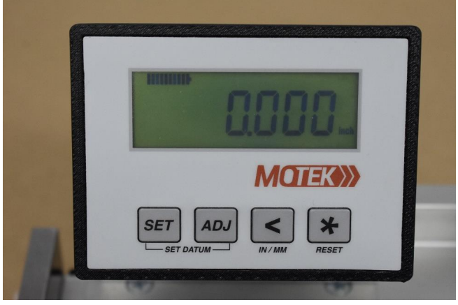
 : Set (programming/change parameters)
  : ADJ (increase value of selected digit)
  : Shift cursor left (select digit)
  : Save (save data)
Restoring factory parameters
If DRO parameters are inadvertently changed and you need to reset them, use the following procedure to restore the factory parameters:
- Hold down for 3 seconds to enter parameter mode, the DRO should display “SETUP”
- Press, the DRO should display “Unit”
- Press again to begin setting parameters back to default
- To navigate through the parameters:
- Press to scroll from one parameter to the next
- Press a second time and the current parameter value will flash on the display
- Press to change the value for that item
- When the correct value is set, press to save
- Press to move on to the next parameter
- Press
- Continue following these steps to set each parameter until you have made it through allparameters. After the final parameter, the DRO will return to its home screen. The DMM can nowbe referenced then you are ready to measure.
The table below contains the factory default values:
Parameter | Value |
Unit | 1dEc |
rES | 0.001 |
dir | uP |
F_nn1 | yES |
F_rEL | No |
F_rST | yES |
F_rEF | yES |
rEF | 000.000 |
F_oFS | No |
rESET | No rSt |
Note – For more explanation as to what other parameter options do to the machine.
Setting the datum
The datum is the value that the DRO resets to when referencing the DMM. From the factory, the datum value is set to 0. If you prefer to zero your DMM as you would handheld calipers (by bringing the jaws together and resetting to 0), there is no need to adjust the datum. If you would prefer to reference the system to a verified length standard or gauge block, you can set the datum to the measurement of that length standard or gauge block. To change the datum:
- Press and on the DRO simultaneously (the datum value will begin flashing)
- Use to move through the digits (selected digit will flash) and to change the value for that digit
- Once you have the DRO showing the desired datum, press to save the changes and to return to the measurement screen
- Now, when you reference your DMM, it will reset to the datum instead of to 0
Note – If pressing ![]() and
and ![]() simultaneously does not take you to the screen to change the datum, enter the parameters menu and make sure “f_rEF” is set to “yES”. If you prefer to always zero your DMM, this value should be left at 0.000.
simultaneously does not take you to the screen to change the datum, enter the parameters menu and make sure “f_rEF” is set to “yES”. If you prefer to always zero your DMM, this value should be left at 0.000.
Referencing the system/zeroing the system
Referencing the system refers to resetting the DRO to the datum value. This is similar to the process of zeroing a pair of calipers or a micrometer except the DMM allows the operator to change the datum value that the DMM can be referenced to.
- Hold down until the DRO displays “rESEt”
- Press the button again, the current measurement will begin to flash
- Place your length standard or gauge block consistent with your datum value on the measuring surface (if you are zeroing your DMM, skip this step)
- Bring the jaws together until the standard sits tightly against both jaws (if you are zeroing your DMM, close the jaws, ensuring there are no obstructions, such as metal chips or debris)
- Press again and the system will reset to the datum
Changing the unit of measure
Your DMM can measure in both inches and millimeters. Operators can quickly switch back and forth using the following procedure:
- Hold down for 3 seconds
- The DRO should change from displaying inches to millimeters or vice versa. Check the lower right-hand corner to see which unit is being displayed
Note: If the unit of measure does not change, check your parameters to ensure that the “F_nn1” parameter is set to “yES”.
Battery replacement
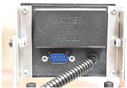
The battery is located on the rear of the DRO behind a plastic cover. To remove the cover, push in on the ends and pull straight out.
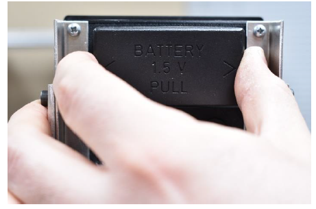
With the cover removed, you can see that the battery is held in by two plastic fingers, one on top and one on the bottom.
Push one of these fingers away from the battery while removing the positive end, as shown.
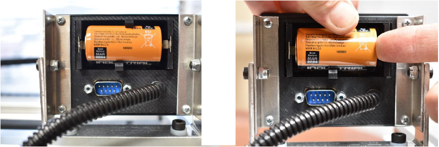
Pivot the battery from the negative end until it clears the plastic fingers and can be fully removed.
Note – During battery replacement, you should never use tools to remove the battery or pry against the DRO housing. This can result in the battery compartment pulling loose from the DRO or the solder joints between the battery connectors and the circuit board being pulled loose. For proper battery removal push out on the tabs securing the battery while pulling out on the positive end and it will come free.
Damage caused by improper battery removal will not be covered under warranty
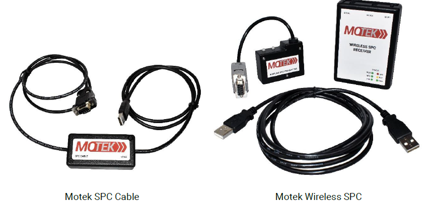
RS232 port
Your DRO is equipped with an RS232 port below the battery compartment. This port allows you to export data directly from your DRO to your computer via one of two optional SPC accessories. Motek offers both wireless and wired SPC accessories that enable the SPC output function of the DMM to transmit data to a PC by pressing . For more information or to purchase one of these devices please visit the Motek store on Amazon.
Setup Guide
Here are the steps to operate, assemble, and configure the motekind Digital Measuring Machine:
- Insert the batteries or connect the USB power supply.
- Turn on the device by sliding the power switch.
- Select the measurement unit (mm or inches) by pressing the "Mode" button.
- Place the end of the measuring tool on the object you want to measure.
- Read the measurement on the LCD screen.
- To turn off the device, slide the power switch to the "Off" position.
Safety Instructions and Obligations
- General safety
Operators of the DMM should always be cognizant of their surroundings. As a check fixture, the DMM may be in the vicinity of many hazards that require the operator’s attention. Additionally, these machines may be used to measure heavy parts and general precautions should be taken to minimize the chances of crushing or pinching hazards between the jaws, the item be measured and the jaws, or the item to be measured and the guide rail. In addition to these safety concerns specific to the DMM, all shop and/or organizational safety rules should always be followed while working with your DMM. - Owner obligations
The owner agrees to only allow the measuring machine to be used by qualified and trained persons who have read and understand this instruction manual. - Operator obligations
Before operating, all persons working with this gauge agree to familiarize themselves with the machine and this instruction manual. Each operator is responsible for following all safety guidelines and for the safe and proper operation of the DMM. - Intended use
The only acceptable use for the DMM is as a measuring system. Any other use is not intended and is a misuse of the measuring system. Motek is not liable for any damages resulting from misuse.
Intended use also means:- Following all safety precautions mentioned in this manual
- Following the maintenance and inspection procedures as mentioned in this manual
Maintenance Requirements
Maintenance schedule
See Section | Component | Clean | Lubricate | Adjust |
4.3 | Guide Rail | X | -- | -- |
4.4 | Magnetic Scale | X | -- | -- |
4.5 | Carriage | X | -- | -- |
4.6 | Jaws | X | X | O |
4.7 | Sensor | X | -- | O |
Legend: X – Daily O – As needed -- Not required
Lubricants and detergents
Detergent
- Use commercially available detergents
- Don’t use any acids or alkaline solutions
- Don’t use any high-pressure water jet cleaners
Lubricant
- The recommended lubricant is 3-IN-ONE oil or equivalent
Guide rail
Remove chips, grease and any other items that would be deemed in the pathway of, or cause an unwanted obstruction to, the carriage. This should be done several times per day if the machine is in heavy use.
Magnetic scale
The magnetic scale is what the sensor reads to produce the measurements on the DMM. It is located on the backside of the guide rail and should periodically be cleaned and checked for damage.
- Remove chips and grease on the magnetic scale and between the sensor and scale. This should be checked daily to ensure there is no development of debris or obstructions. If heavy chip or debris accumulation occurs, increase frequency to accommodate suitable maintenance measures.
- The sensor-to-scale gap should be within the range of 0.003” to 0.030” (sensor gap and alignment covered more in depth in section 4.7).
Chemical Resistance
Acetone | ** | Ketone | *** |
Acetylene | ** | Mineral oil | * |
Benzene | *** | Seawater | ** |
Gasoline | ** | Steam heat | * |
Heptane | *** | Thinner | *** |
Kerosene | * | Turpentine | ** |
* - Little-to-no effect **- Low-to-moderate effect ***- Severe effect | |||
Carriage
- Remove chips, grease and any items on the measuring surface that would be deemed in the pathway of, or cause an unwanted obstruction to, the carriage or jaws. This should be done several times per day if the machine is in heavy use.
- Ensure that the hardware connecting the jaws to the carriage is secured. This may be checked on a quarterly basis or implemented in line with the standard preventative maintenance schedules for the other equipment in the facility.
HD8645 Jaws
Cleaning
- Wipe down jaws and remove any dirt, grime, or moisture
- Apply a liberal coat of lubricant to every exposed surface of the jaws to prevent corrosion
Adjusting
From the factory, the parallelism of the jaws is set to be ±0.001” across 9 points on the jaws. To maintain accuracy, parallelism of the jaws must be maintained at this specification and should be checked periodically. A ball gage is recommended to check the distance between the jaws at 9 points shown on the smaller jaw face below. The circles on the diagram depict the mounting screw holes. Be sure that when taking measurements, the ball gage is not resting in one of these holes. In the event the measurement at any of these points is off by more than ±0.001”, the jaws should be squared to maintain the machine’s accuracy. There are adjustment procedures for coarse and fine adjustment. If the measurements vary by ±0.005” or more, begin with the coarse adjustment. If not, skip ahead to fine adjustment.
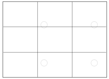
The grid to the left divides your DMM jaw in to 9 sections. Take a measurement at the center of each of these sections, being sure not to take measurements with your ball gage in one of the mounting screw holes.
In order to adjust the jaws on your DMM, you will need a 2.5mm and a 4mm hex key. If your DMM needs coarse adjustment, you will also need something to clamp the jaws together. (A small locking C-clamp, as shown, is recommended [figure 2, page 8].)
Coarse adjustment
- With the 4mm hex key, slightly loosen the four mounting screws holding the smaller jaw to the carriage bracket (figure 1).
Clamp the two jaws together using the hole in the center of the bracket as shown, being careful to avoid clamping the bracket as well. While tightening the clamp, align the top and outside edge of the jaws (figure 2).
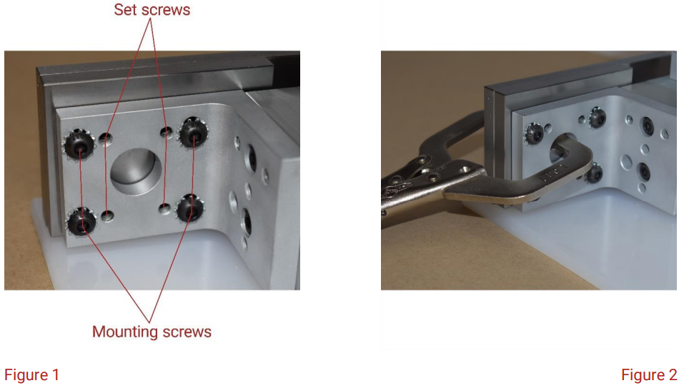
- Run the set screws in using the 2.5mm hex key until they lightly touch the jaw.
- Tighten the mounting screws to 20 in/lbs and recheck parallelism of the jaws.
Fine adjustment will most likely be necessary, but if everything falls within the specification of ±0.001” across the 9 points, you are finished adjusting and can reference your DMM to begin measuring.
Figure 1
Fine adjustment
- Check the jaws at the 9 points again and record the measurements. Start at the point with the lowest measurement and tighten the corresponding set screw very slightly (approximately 10-15 degrees at a time). If you have to tighten a set screw more than a half turn, back the mounting screw out and re-torque the nearest mounting screw to 20 in/lbs.
- Recheck the measurement at that point and the adjacent points.
- Continue checking the 9 points and adjusting the set screws accordingly until all points measure±0.001”.
Note: At no point should any of the screws be overly tightened. Over-tightening the mounting screws may cause the jaw to bow and prevent you from getting the parallelism of the jaws into spec. Mounting screws should be tightened to a torque of 20 in/lbs.
Sensor alignment
Figure 3, below, depicts the proper sensor alignment for accurate measuring. The sensor and bracket should be tight, the sensor should be level with the scale, and there should be a uniform distance between the sensor and the scale (dimension D, figure 3) of 3 to 30 thousandths of an inch (0.003”-0.030”). If the sensor does not meet these criteria, follow the steps below to adjust it.
- Loosen the sensor mounting screws slightly (figure 3).
Loosen the bracket mounting screws slightly (figure 4).
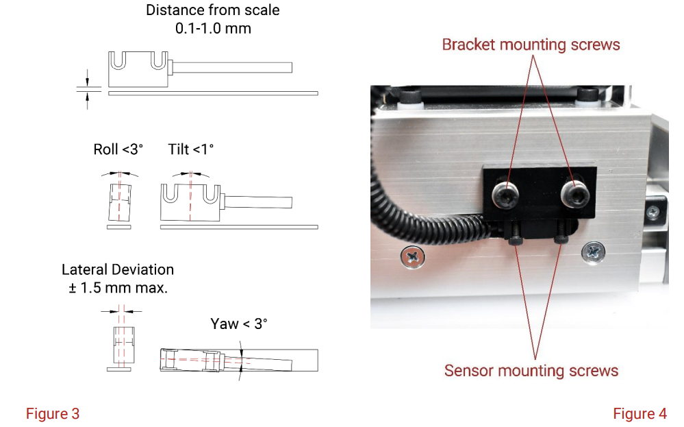
- Pull the sensor up tightly to the top of the window machined into the carriage and tighten the bracket mounting screws.
- Insert a feeler gauge with a thickness within the acceptable gap range between the sensor and the scale. Be sure that the feeler gauge is inserted far enough to maintain the proper gap throughout the full length of the sensor.
- Push in the sensor so that it touches the feeler gauge and continue holding in on it as you tighten the sensor mounting screws.
- Remove the feeler gauge from between the sensor and the scale
- Using a set of verified length standards or gauge blocks, check various measurements to see if the DMM is now measuring within spec.
Troubleshooting
Problem | Solution |
DRO won’t power on |
The DRO is constantly under power. If your DRO isn’t on the battery may be dead. Replace the battery. (Section 5.6) |
DRO won’t zero/reference |
If you can’t get your DMM to zero or reference, most likely the “F_rST” parameter has been changed to “no”. Follow the procedure for restoring factory parameters andchange “F_rST” to “Yes”.
If your DMM allows you to reset to zero but doesn’t allow you to change the datum to reference the system to a different length, parameter “F_rEF” has been changed to “no”. Follow the procedure forrestoring factory parameters and change “F_rEF”to “Yes”. (Section 5.2) |
When zeroing the system DRO resets to a value other than zero |
If you are attempting to zero the system andyour DRO resetsbut it resets to a value other than zero, a datum value has been entered in the DRO.To change the datum back to zero,press the |
DRO reading erratically or measurements are off varying amounts at various points |
Examine themagnetic scale on the rearof the guiderail for signs of damage.
If thereis no damage, check to see if yoursensor is tightand your sensor-to-scale gap is withinspec. (Section 4.7) |
Measurements are off a set amount the full measuring length |
Close the jawsIf the DMM is not displaying zero,zero it.
Check the parallelism of the jaws.If they aren’tparallel adjust them to make them parallel. (Section 4.6) |
Parameters List
The following chart outlines all the possible options for the various parameters in the DRO. Some of these parameters could make your DMM non-functional. Be sure before experimenting with parameter options, you are familiar with how to return all parameters to the factory settings.
Note – Factory DMM settings are highlighted in Red and Bolded
Parameter | Description |
Unit |
Determines what type of measuring the DRO will perform (linearor angular) as well as, the unit of measure (inches, mm, degrees).
DEC – Linear measurement display in decimal FrEE – Display with conversion factor dG1 – Angular display dG2 – Angular display IdEC – Inch display mode Ifrct – Fractional inch mode (all separated withdecimals, 15 13/64”would display 15.13.64) |
COn |
Allows operator to set a free conversion factor to display non-metric units, angles, or usedas a scaling factor to correct linearinaccuracies.
Value range: FrEE = 0.00001-1.00000 dG1, dG2 = 0.00001 – 9.99999
*parameter only availablewhen Unit = FrEE, dG1, or dG2. |
rES | Sets the resolution of the display. Options: Unit (dEC, FrEE,dG1, or dG2) – 0.001,0.005, 0.01, 0.05,0.1, 0.5, 1
Unit (IdEC) – 0.0001, 0.0005, 0.001, 0.005, 0.01, 0.05, 0.1
*parameter only available when Unit = dEC, FrEE, dG1, dG2, or IdEC |
Dir |
Sets thecounting direction of the sensor.
uP – up (standard counting direction) dn – down (inverted counting direction) |
F_nnI | Enables switching back and forth from inches to millimeters by holding down yES– enabled (holding |
F_rEL |
Enablesthe incremental measurement function.
yES – Enabled (allows changing the DRO to incremental measuring by pressing no – Disabled (DRO stays in absolute measuring) |
F_rSt |
Turns the referencing/zeroing function on or off.
yES– Enabled (holding down no – Disabled (DRO cannot be referenced) |
F_rEF |
Allows modification of the datum value the DROreferences to by pressing yES– Enabled (operator can change thedatum and the DRO willreference to that value) no – Disabled (operator cannot change the datum valueand the DRO can onlybe referenced to 0) |
F_oFS | Allows addingoffset values to the DROmeasurements. OFS1 can be adjusted by pressing yES – Enabled(operator can applyoffset values to the DRO measurement) no – Disabled (operator cannot apply offsetvalues to theDRO measurement)
*If F_oFS is previously set to yES and a value is entered for OFS1, the value must be changed to 0 before changing F_oFS to “no” or the offset will continue to be applied. |
rEF |
This valueis your datum(the value thatthe DRO resetsto when Value canbe changed eitherin parameters menuor by pressing Value range (-999999 to 999999)
*this parameter is only available if F_rSt is setto yES. |
OFS1 | This is the firstoffset value, it is addedto the measured value. This valuecan be adjusted by pressing Value range(-999999 to 999999)
*this parameter is only available if F_oFS is set to yES |
OFS2 |
This is the secondoffset value, it is addedto the measured value+OFS1. This value is onlyadjustable through the parameter menu.
Value range (-999999 to 999999)
*this parameter is only available if F_oFS is set to yES |
OFS 3 |
This is the thirdoffset value, it is addedto the measured value+OFS1+OFS2. This value is onlyadjustable through the parameter menu.
Value range (-999999 to 999999)
*this parameter is only available if F_oFS is set to yES |
Pros & Cons
Pros
- Easy to use
- Precise and accurate measurements
- Large LCD screen with backlight
- Compact and lightweight
- Versatile and durable
Cons
- May not be suitable for very small or very large measurements
- Batteries may need to be replaced frequently
Saeco Automatic Espresso Machine HD8645 Warranty
Motek Industries warrants this product for a period of twelve (12) months from the date of shipment. During the warranty period, under authorization from Motek Industries, return component parts freight prepaid. The company will repair or replace, at its option, any part found to be defective in material or workmanship, without charge to the owner for parts, service labor, or associated shipping costs. This same protection will extend to any subsequent owner during the warranty period. It does not apply to damage caused by accident, misuse, fire, flood, acts of God, or from failure to properly install, operate, or maintain the product in accordance with the printed instructions provided.
Customer Reviews
Customers love the motekind Digital Measuring Machine for its ease of use and accuracy. They appreciate the large LCD screen and compact design, and many have used it for various projects such as woodworking, engineering, and DIY repairs. Some customers have noted that the battery life could be longer, but overall they are satisfied with the product.
Faqs
What types of coffee can the Saeco Automatic Espresso Machine HD8645 make?
Is the machine easy to clean?
Can I use pre-ground coffee?
Does it have a milk frother?
Is there a warranty for the machine?
How long does it take to brew a cup of coffee?
What type of maintenance does Saeco Automatic Espresso Machine HD8645 require?
Is the machine suitable for small kitchens?
Can I program the machine for a specific brew time?
Leave a Comment