Mrcool Prodirect Air Handler Refrigerator HAH14OC User Guide
Content
Introduction
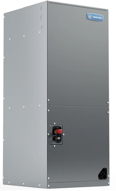
The Mr. Cool ProDirect Air Handler Refrigerator HAH14OC is a high-efficiency air handling unit designed for optimal climate control in residential and commercial spaces. Featuring a durable galvanized steel cabinet, it is built to withstand various environmental conditions while providing reliable performance. The air handler supports multi-position installation and includes a removable filter for easy maintenance. With its advanced technology and energy-efficient operation, the HAH14OC is priced at approximately $1,299.00.
Specifications
- Capacity: 14,000 BTU
- Refrigerant Type: R-410A
- Temperature Range: 40°F to 80°F
- Air Flow Rate: Up to 400 CFM
- Power Consumption: 120V, 60Hz, 15A
- Dimensions: 24" x 24" x 12"
- Weight: Approximately 70 lbs
- Noise Level: Less than 40 dB
- Certifications: UL, ETL, and Energy Star compliant
GENERAL
- The unit can be positioned for bottom return air in the upflow position, left and right return in the horizontal position, or top return in the downflow position.
- This Air Handler provides the flexibility for installation in any upflow, downflow, or horizontal application. The direct drive motors provide a selection of air volumes to match any application. The 3-Speed motor can be adjusted to provide air flow to meet desired applications.
- Top and side power control wiring, and accessible screw terminals for control wiring, all combine to make the installation easy, and minimize installation cost. Please contact your local distributor (Refer to Fig.1).
- The appliance is only intended to supply conditioned air to one room.
UNIT DIMENSIONS
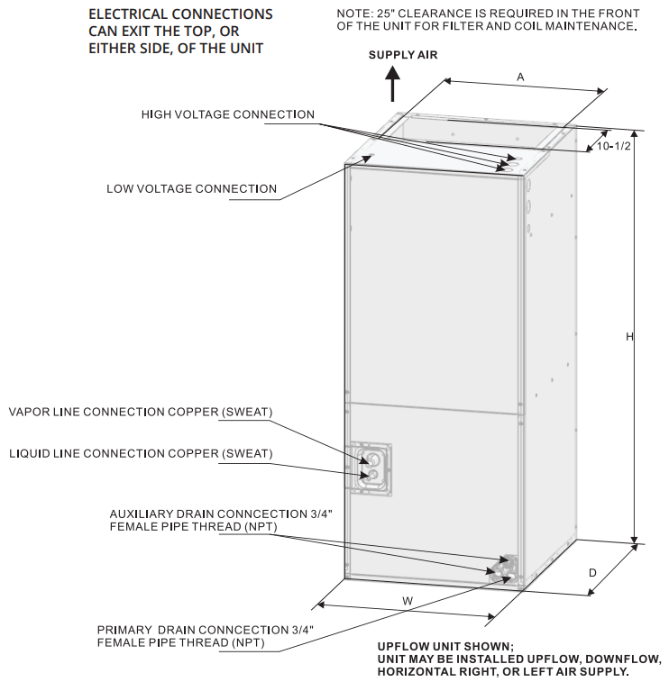
DIMENSIONS DATA
Table 1
MODEL SIZE | Dimensions inch [mm] | ||||
UNIT HEIGHT (H) in [mm] | UNIT WIDTH (W) in [mm] | UNIT DEPTH (D) in [mm] | SUPPLY DUCT (A) in [mm] | LIQUID LINE/ VAPOR LINE in | |
18K | 45.75 [1162] | 19.69 [500] | 22.05 [560] | 17.87 [454] | 3/8” / 3/4” |
24K | 45.75 [1162] | 19.69 [500] | 22.05 [560] | 17.87 [454] | 3/8” / 3/4” |
30K | 45.75 [1162] | 19.69 [500] | 22.05 [560] | 17.87 [454] | 3/8” / 3/4” |
36K | 45.75 [1162] | 19.69 [500] | 22.05 [560] | 17.87 [454] | 3/8” / 3/4” |
42K | 45.75 [1162] | 19.69 [500] | 22.05 [560] | 17.87 [454] | 3/8” / 3/4” |
48K | 53.15 [1350] | 22.05 [560] | 24.53 [623] | 19.53 [496] | 3/8” / 7/8” |
60K | 53.15 [1350] | 22.05 [560] | 24.53 [623] | 19.53 [496] | 3/8” / 7/8” |
VERTICAL UPFLOW
- Vertical Upflow configuration is the factory set on all models (Refer to Fig 1).
- If a side return air opening is required, field fabricate a return air plenum with an opening large enough to supply the unit and strong enough to support the unit’s weight.
- If return air is to be ducted, install duct flush with floor. Use fireproof resilient gaskets with a thickness of 1/8 in. to 1/4 in. (3.18 mm to 6.35 mm) , between the ducts, unit, and floor. Set the unit on the floor over the opening.
IMPORTANT NOTE:
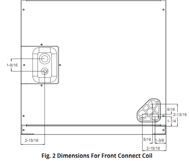
Torque applied to drain connections should not exceed 15 ft-lbs (20.34 Nm) (Refer to Figs. 1 & 2).
VERTICAL DOWNFLOW
Conversion to Vertical Downflow: A vertical upflow unit may be converted to vertical downflow. Remove the door and indoor coil and reinstall 180 degrees from its original position (Refer to Fig. 3).
IMPORTANT: To comply with certification agencies and the National Electric Code for horizontal right application, the circuit breaker(s) on field-installed electric heater kits must be re-installed, per the procedure below, so that the breaker switch ”on” position and marking is up and, ”off” position and marking is down. To rotate the circuit breakers please follow the steps below.
To rotate breaker(s): Rotate one breaker set (circuit) at a time, starting with the one on the right. Loosen both lugs on the load side of the breaker (make sure that wires are identified and are reinstalled into proper breaker). Wires are bundled with wire ties, one bundle going to the right lug and one bundle going to the left lug. Use the steps on the following page to complete this process.
- Using a screwdriver, lift the blue plastic tab with a hole away from the breaker. Continue doing this until breaker releases from its position.
- With breaker held in hand, rotate breaker so that the ”on” position is up, and ”off” position is down (with unit in planned vertical mounting position). Insert right wire bundle into top right breaker lug, ensuring all strands of all the wires are inserted fully into lug, and no wire insulation is in the lug.
- Tighten lug as tight as possible, while holding circuit breaker. Check wires and make sure each wire is secure and none are loose. Repeat for left wire bundle in left top circuit breaker lug.
- Replace breaker by inserting the breaker mounting tab, opposite of the white pull tab in opening, hook mounting tab over edge in opening.
- Using a screwdriver, pull the blue tab with a hole away from the breaker, while setting that side of the breaker into the opening. When breaker is in place, release tab, which will lock circuit breaker into location in opening.
- Repeat above operation for remaining breaker(s) (if more than one is provided).
- Replace single point wiring jumper bar, if it is used, on line side of breaker and tighten securely.
- Double check wires and lugs to make sure all are secure and tight. Check to make sure unit wiring to circuit breaker load lugs match that shown on the unit wiring diagram.
CAUTION: When using the unit with the electrical heater, the switch on the front of the panel is only used for the electrical heater.
HORIZONTAL
Horizontal right is the default fa ctory configuration for the units.
Conversion to Horizontal
A vertical upflow unit may be converted to horizontal left by removing indoor coil assembly and reinstalling coil in the unit as described in the steps below:
- Rotate unit into the downflow position, with the coil compartment on top and the blower compartment on bottom (Refer to Fig. 3).
- Reinstall the indoor coil 180° from the original position. Ensure the retaining channel is fully engaged with the coil rail (Refer to Fig. 3).
NOTE: Secondary drain pan kits are recommended when the unit is configured for the horizontal position over a finished ceiling and/or living space.
CAUTION
Horizontal units must be configured for right-hand air supply or left-hand air supply. The horizontal drain pan must be located under indoor coil. Failure to use the drain pan can result in property damage.
Conversion in Horizontal Direction
Horizontal right-hand supply can be changed to horizontal left-hand supply by removing the indoor coil, rotating it 180 degrees from the original position, and then reinstalling it.
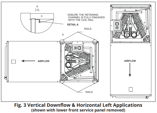

TABLE 2
14SEER AHU | ||||||||
Market Model | HAH14018 | HAH14024 | HAH14030 | HAH14036 | HAH14042 | HAH14048 | HAH14060 | |
Indoor external static pressure |
InWC |
0.10 |
0.10 |
0.15 |
0.15 |
0.15 |
0.20 |
0.20 |
Indoor air flow | CFM (hi/mi/lo) | 723/610/500 | 938/804/738 | 1204/1060/919 | 1376/1235/1161 | 1562/1385/1208 | 1695/1574/1434 | 1695/1574/1434 |
Indoor external static pressure |
InWC |
0.18 |
0.18 |
0.23 |
0.23 |
0.23 |
0.28 |
0.28 |
Indoor air flow | CFM (hi/mi/lo) | 1364/1229/849 | 1595/1366/1256 | 2046/1955/1562 | 2340/2100/1974 | 2480/2430/2074 | 2882/2676/2437 | 2882/2676/2437 |
ELECTRICAL WIRING
Field wiring must comply with the National Electric Code and any applicable local ordinance.
If required, install a branch circuit disconnect of adequate size, located within sight of, and readily accessible to the unit.
IMPORTANT: After the Electric Heat Kit is installed, units may be equipped with one, two, or three 30/60 amp. circuit breakers. These breaker(s) protect the internal wiring in the event of a short circuit and also serve as a disconnect. Circuit breakers installed within the unit do not provide overcurrent protection of the supply wiring and therefore may be sized larger than the branch circuit protection.
- Supply circuit power wiring must be 167°F (75°C) minimum copper conductors only. Refer to the Electrical Data In this section for ampacity, wire size, and circuit protector requirement. Supply circuit protective devices may be either fuses or “HACR” type circuit breakers.
- Power wiring may be connected to either the right side, left side, or top. Concentric knockouts are provided for connection of power wiring to unit.
- Power wiring is connected to the power terminal block in unit electric cabinet.
CONTROL WIRING
IMPORTANT: Class 2 low voltage control wiring should not be run in conduit with main power wiring and must be separated from power wiring, unless class 1 wire of proper voltage rating is used.
- Low voltage control wiring should be 18 AWG and color-coded. For lengths longer than 100 ft., 16 AWG. wire should be used.
- See wiring diagrams attached to indoor and outdoor sections to be connected.
- Make sure, after installation, separation of control wiring and power wiring has been maintained.
GROUNDING
WARNING: The unit must be properly and permanently grounded. Failure to do so can result In electrical shock causing personal injury or death.
- Grounding may be accomplished by grounding metal conduit when installed in accordance with electrical codes to the unit cabinet.
- Grounding may also be accomplished by attaching ground wire(s) to ground lug(s) provided in the unit wiring compartment.
- Ground lug(s) are located close to the wire entrance on the left side of the unit (upflow). Lug(s) may be moved to marked locations near the wire entrance on right side of the unit (upflow) If this alternate location is more convenient.
- Use of multiple supply circuits require grounding of each circuit to lug(s) provided in unit.
ELECTRICAL DATA
Table 3 (Applicable to 13-14 SEER)
MODEL | VOLTAGE | HERTZ | HP | RPM (low/med/high) | SPEEDS | CIRCUIT AMPS | MAXIMUM CIRCUIT PROTECTOR |
18K | 208/230 | 60 | 1/7 | 340/390/440 | 3 | 0.73 | 5(A) |
24K | 208/230 | 60 | 1/6 | 490/530/570 | 3 | 0.80 | 5(A) |
30K | 208/230 | 60 | 1/4 | 530/600/670 | 3 | 1.21 | 5(A) |
36K | 208/230 | 60 | 2/7 | 690/730/805 | 3 | 1.53 | 5(A) |
42K | 208/230 | 60 | 3/8 | 610/723/839 | 3 | 1.95 | 5(A) |
48K | 208/230 | 60 | 2/5 | 820/870/920 | 3 | 1.92 | 5(A) |
60K | 208/230 | 60 | 2/5 | 820/870/920 | 3 | 2.55 | 15(A) |
- The air distribution system has the greatest effect on airflow. The duct system is totally controlled by the contractor. For this reason, the contractor should use only industry-recognized procedures.
- Heat pump systems require a specified airflow. Each ton of cooling requires between 350 and 450 cubic feet of air per minute (CFM), or 400 CFM nominally. Duct design and construction should be carefully done. System performance can be lowered dramatically through bad planning or workmanship.
- Air supply diffusers must be selected and located carefully. They must be sized and positioned to deliver treated air along the perimeter of the space. If they are too small for their intended airflow, they become noisy. If they are not located properly, they can create drafts. Return air grilles must be properly sized to carry air back to the blower. If they are too small, they also cause noise.
- The installers should balance the air distribution system to ensure proper, quiet airflow to all rooms in the home. This ensures a comfortable living space. An air velocity meter or airflow hood can give a reading of system CFM.
REFRIGERANT CONNECTIONS
- Keep the coil connections sealed until refrigerant connections are made. See the Installation Instructions for the outdoor unit for details on line sizing, tubing installation, and charging information.
- Coil is shipped with “No charge”. Evacuate the system before charging with refrigerant.
- Install refrigerant tubing so that it does not block service access to the front of the unit.
- Nitrogen should flow through the refrigerant lines while brazing.
- Use a brazing shield to protect the cabinet’s paint, and a wet rag to protect the rubber grommet from being damaged by torch flames. After the refrigerant connections are made, seal the gap around the connections with a pressure sensitive gasket.
TXV EXPANSION VALVE INFORMATION

Thermal Expansion Valve Specifications 18K/24K/30K/36K Capacity Units Emerson NCE3ZAA ODF | |||||||||||
No. | BOM | A | B | C | D | E | F | G | H | L1 | L2 |
1 | 801600400099 | 0.50 in (12.7 mm) | 0.375 in (9.52 mm) | 0.94 in (24 mm) | 1.28 in (32.5 mm) | 1.65 in (42 mm) | 1.65 in (42 mm) | 0.71 in (18 mm) | 1.06 in (27 mm) | 31.50 in (800 mm) | 31.50 in (800 mm) |
Units: inch (millimeter) 42K/48K/60K Capacity Units Emerson NCE5ZAA ODF | |||||||||||
No. | BOM | A | B | C | D | E | F | G | H | L1 | L2 |
1 | 801600400101 | 0.50 in (12.7 mm) | 0.375 in (9.52 mm) | 0.94 in (24 mm) | 1.28 in (32.5 mm) | 1.65 in (42 mm) | 1.65 in (42 mm) | 0.71 in (18 mm) | 1.06 in (27 mm) | 31.50 in (800 mm) | 31.50 in (800 mm) |
A: Outletinner diameter Units:inch (millimeter) B: Inlet diameter C: Lengthfrom outlet centerto bottom of valve body D: Length from inlet center to bottom of valve body E: Length from outlet center to valve body center F: Length frominlet center to valve bodycenter G: Lengthbetween the centerof the adjustable screw and theback of thevalve body H: Length between the center of valve body and bottom of valve body L1: Balance tube length L2: Warm wire length | |||||||||||
CONDENSATE DRAIN TUBING
Consult Local Codes for Specific Requirements

IMPORTANT:
- When making drain fitting connections to the drain pan, use a thin layer of Teflon paste, silicone, or Teflon tape and on the connections before they are installed. Hand-tighten the fittings.
- When making drain fitting connections to the drain pan, do not over-tighten them. If the fittings are over-tightened it can cause the pipe connections to split on the drain pan.
- Install drain lines so they do not block service access to front of the unit. A minimum clearance of 2 ft (609.6 mm) is required for filter, coil or blower removal, and service access.
- Make sure unit is level or pitched slightly toward the primary drain connection so that water will drain completely from the pan (Refer to Fig. 5)
- Use a drain line that is properly sized to match the size of condensate drain pan.
- All drain lines must be pitched downward and away from the unit with a minimum of 1/8 in. per foot of line to ensure proper drainage.
DO NOT connect condensate drain line to a closed or open sewer pipe. Run condensate to an open drain or run line to a safe outdoor area. - The drain line should be insulated where necessary to prevent sweating and damage from condensate forming on the outside surface of the line.
- Make provisions for disconnecting and cleaning of the primary drain line should it become necessary. Install a 3 in (76.2 mm) trap in the primary drain line as close to the unit as possible. Make sure that the top of the trap is below the connection to the drain pan to allow complete drainage of pan (Refer to Fig. 5).
- An auxiliary drain line should be run to a place where it will be noticeable if it begins to drain. The homeowner should be warned that a problem exists if water should begin running from the auxiliary drain line.
- Plug the unused drain connection with the plugs provided in the parts bag, using a thin layer of teflon paste, silicone, or teflon tape to form a water tight seal.
- Test condensate drain pan and drain line after installation is complete. Pour water into the drain pan. Ensure the amount poured is enough to fill drain trap and line. Check to make sure drain pan is draining completely, no leaks are found in the drain line fittings, and water is draining from the termination of the primary drain line.
AIR FILTER (NOT FACTORY-INSTALLED)
An external filter, or other means of filtration, is required. Units should be sized for a maximum of 300 feet/min. air velocity, or what is recommended for the filter type installed.
Filter application and placement are critical to airflow, which may affect the heating and cooling performance of the system. Reduced airflow can shorten the life of the system’s major components, such as the motor, limits, elements, heat relays, evaporator coil, and/or compressor. Consequently, we recommend that the return air duct system have only one filter location. For systems with a return air filter grill or multiple filter grills, they can have a filter installed at each of the return air openings.
If adding high efficiency filters or electronic air filtration systems, it is very important that the airflow is not reduced by these. If airflow is reduced, the overall performance and efficiency of the unit will also be reduced. It is strongly recommended that a professional installation technician is contacted to ensure these filtration systems are installed correctly.
IMPORTANT:
- DO NOT USE MORE THAN ONE FILTER IN THE RETURN AIR DUCT SYSTEM.
- DO NOT INSTALL A FILTER FOR THE SUPPLY AIR DUCT SYSTEM.
- THESE WILL REDUCE AIRFLOW AND AFFECT THE PERFORMANCE OF THE UNIT!
WARNING
DO NOT operate the system without filters. A portion of the dust in the air may temporarily lodge in the duct runs and at the supply registers. Any circulated dust particles could be heated and charred by contact with the air handler elements. This residue could soil ceilings, walls, drapes, carpets, and other articles in the house. Soot damage may occur with filters in place, when certain types of candles, oil lamps, or standing pilots are burned.
FILTER INSTALLATION DIMENSIONS

Air Filter Dimensional Data
Table 4

AIR FILTER REMOVAL
- Remove the two bolts marked A and B. Then remove the cover for air filter (Refer to Fig. 6).
- Hold the edge of the air filter and extract it.
Clean the air filter by using a vacuum cleaner or pure water (Refer to Fig. 7).
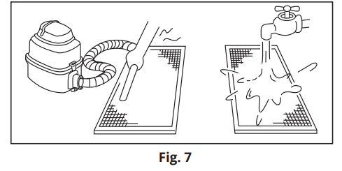
NOTE: If the air filter has a heavy amount of dust accumulation, use a soft brush and mild detergent to clean it. Then, allow it to dry out in a cool place.
Description
The mrcool Prodirect Air Handler Refrigerator HAH14OC boasts a sleek and compact design, making it easy to install in confined spaces. The unit features a high-efficiency compressor and a durable coil system that ensures reliable performance over an extended period. It also includes advanced features such as a programmable thermostat, automatic defrost function, and a filterless design for reduced maintenance.
The air handler's robust construction and weather-resistant casing make it suitable for both indoor and outdoor installations. Additionally, its quiet operation and low vibration ensure minimal disturbance, making it an excellent choice for noise-sensitive environments.
WIRING DIAGRAMS
Thermostat Wiring - 6 Conductor | 18 Gauge | Low Voltage
Control Wiring for A/C Systems only

Control Wiring for Heat Pump Systems

High Voltage Wiring
- To avoid the electrical shock, please connect the air conditioner with the ground lug. The main power plug in the air conditioner has been joined with the ground wiring, please do not change it freely.
- Use a dedicated circuit.
- DO NOT pull the power wiring hard.
- When connecting the air conditioner with the ground, observe the local codes.
- If necessary, use the power fuse, circuit breaker, or the corresponding scale ampere.
Applicable to 18k, 24k, 30k, 36k, 42k of 13-14 SEER

Applicable to 48K of 13-14 SEER

Applicable to 60K of 13-14 SEER
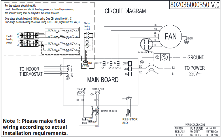
Instructions to Adjust Blower Volume Speed
To adjust blower speed, use the diagram below to wire according to the desired speed:
CN11 is the air volume output port. The air volume is adjusted by connecting one of the wires, each represents a different motor speed, to the port CN11. Regardless of the speed selected, only one wire should be connected to terminal CN11. Terminals CN12 & CN13 should be used as parking terminals for the two unused wires to be connected to.
NOTE: The circuit board used in the 18K, 24K, 30K, 36K,& 42K capacity units is shown below as an example, but the same applies for the circuit boards used in the 48K and 60K units.
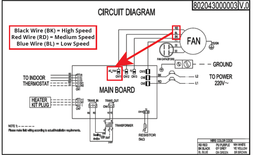
Air Handler Main Board Diagram

Fan Motor Terminals
- AC Fan Port: Used to Adjust Fan Speed/Output
- CN12 (F1) & CN13 (F2) Ports are Reserved
ELECTRIC WIRING GAUGE
NOTE: The cross-section areas of wires or lines should not be less than the corresponding line measurements listed in the tables below; Additionally, if the power wires from the unit are quite long, please select wiring that has a larger cross-sectional area in order to help guarantee a normal supply of power over the distance of the wiring.
Table 5

Table 6

Setup Guide
To operate the mrcool Prodirect Air Handler Refrigerator HAH14OC, follow these steps:
- Unpack the unit carefully and ensure all components are included.
- Choose a suitable location with adequate airflow and protection from direct sunlight.
- Connect the power cord to a 120V, 60Hz electrical outlet.
- Install the thermostat according to the user manual instructions.
- Turn on the unit and set the desired temperature using the control panel.
- Regularly check and maintain the air filter to ensure optimal performance.
ELECTRIC HEAT KIT INSTALLATION (OPTIONAL)
CAUTION
- Ensure that all power supply is disconnected prior to installing the heat kit.
- A means of strain relief and conductor protection must be provided at the supply wire entrance into cabinet.
- Only use copper conductors.
- Installation must follow National Electric Code (NEC) and other applicable codes.
- If this appliance is installed in an enclosed area such as a garage or utility room with any carbon monoxide producing appliance, ensure the area is properly ventilated to the outside.
- A filter dryer is recommended for installation based on nominals tonnage. One should be included and zip-tied to the condenser.
- Use 0.96 as approximate SCFM correction factor for wet coil.
Installation Instructions:
- Refer to the Table below for the appropriate, optional heat kit.
- Check for any physical damage; do not install a damaged heat kit.
- Remove the upper side panel from air handler.
- Remove the air duct sealing plate from the air handler (See Fig. 8).
- Knock out the hole on the front panel.
- Install the heating bracket by sliding it into the air duct hole that you removed the plate from in the previous steps. Align the 4 prongs at the end of the heat kit with the 4 corresponding holes on the opposite side of the air duct hole. Install screws to secure the heat kit to the air handler (See Fig. 9).
- Install the electrical board bracket and screw it into place. Then, position, install, and fasten the electrical board on the bracket which also screws into place (See Fig. 10).
NOTE: When installing the electrical boards, make sure the indoor unit power cable does not snag or come in contact with any of the sharp edges of the sheet metal. Insert the heat kit wiring connector into the correct terminal on the air handler main board (See Fig. 11).

- Reinstall the upper side panel to the air handler and check operation.
Heat Kit Compatibility Chart
Kit #. | Description | Unit CapacityCompatibility |
PHK05H | 5kW heat strip | 18K/24K/30K/36K/42K/48K/60K |
PHK07H | 7.5kW heat strip | 18K/24K/30K/36K/42K/48K/60K |
PHK10H | 10kW heat strip | 24K/30K/36K/42K/48K/60K |
PHK15H | 15kW heat strip | 36K/42K/48K/60K |
PHK20H | 20kW heat strip | 48K/60K |
IMPORTANT: You must use a compatible heat kit listed in the above chart. Using an incorrect size, could cause the unit to overheat and/or cause equipment damage.
Troubleshooting Indoor Unit
Display mode | Status description |
Green light always on | Nosystem alarm and error, normalstandby |
Red light always on | Evaporator temperature sensor (T2)failure |
Green light always on & yellow light flashing | Evaporator highand low temperature protection |
Green light flashing | System is in normal operating status |
T2 Evaporator temperature sensor failure

Temperature °Fahrenheit (°Celsius) | Resistor Value (Kilo-ohms KΩ) |
77°F (25°C) | 5.0 KΩ |
95°F (35°C) | 3.5 KΩ |
Evaporator high-temperature protection (for heating mode)
.png)
Evaporator low-temperature protection (for cooling mode)
.png)
MrCool Refrigerator HAH14OC Pros & Cons
Pros
- High-efficiency cooling system with low power consumption.
- Compact design suitable for confined spaces.
- Advanced features like pa rogrammable thermostat and automatic defrost.
- Quiet operation with minimal vibration.
- Durable construction with weather-resistant casing.
Cons
- Higher initial cost compared to other air handlers on the market.
- Requires professional installation for optimal performance.
- Limited availability of replacement parts in some regions.
Customer Reviews
Customers have praised the cool Prodirect Air Handler Refrigerator HAH14OC for its reliable performance and efficient cooling capabilities. Many have noted its quiet operation and ease of use, making it a favorite among both residential and commercial users. However, some reviewers have mentioned the higher initial cost as a downside.
Common complaints include the need for professional installation and the limited availability of replacement parts in certain areas.
Faqs
What is the cooling capacity of the MrCool?
What type of refrigerant does this air handler use?
What is the temperature range supported by this air handler?
How much power does the MrCool HAH14OC consume?
Is the Refrigerator certified by any regulatory bodies?
How do I troubleshoot if the unit is not cooling?
Can I install the MrCool Prodirect Air Handler Refrigerator myself?
What maintenance is required for the mrcool Air Handler?
Is the mrcool Prodirect Air Handler Refrigerator HAH14OC suitable for outdoor use?
How quiet is the operation of this air handler?
Leave a Comment
