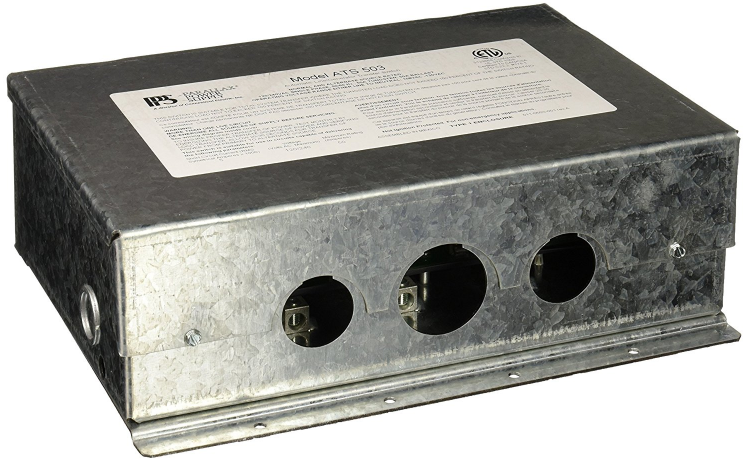
Parallax Power Supply Generator Transfer Switch ATS 503 User Guide

Content

Introduction
The Parallax Power Supply Generator Transfer Switch ATS 503 is a reliable solution for seamless power transfer between utility and generator sources. Launched in 2020, this transfer switch is manufactured by Parallax Power Supply, known for its high-quality power management products. Priced at approximately $199, the ATS 503 is designed for easy installation and operation, ensuring that homes and businesses maintain a continuous power supply during outages, enhancing safety and convenience.
Specifications
- NORMAL AND ALTERNATE SOURCE RATED:
120/240VAC SINGLE PHASE, 50/60 Hz, 50A TUNGSTEN, 50A BALLAST - OPERATING VOLTAGE RANGE:
EITHER LINE TO NEUTRAL, 108VAC -130VAC GEN. NEUTRAL CONTACTS RATED 70A W/ JUMPERS INSTALLED AUX. CONTACTS RATED 35A, 120VAC SINGLE PHASE, 50/60 Hz. - Maximum generator: 12.6 Kw
- Command source:
Generator Enclosure UL Type 1, 16 GA Steel
- Command source:
- Dimensions and Weight: ATS 503 with Mounting Flanges
- Width: 12-3/8”, Height: 4-1/8”, Depth: 9-7/8” - Weight: 10.0 pounds

Description
The Parallax Power Supply Generator Transfer Switch ATS 503 is built with durability and reliability in mind. Its sturdy construction and weather-resistant design make it suitable for both indoor and outdoor installations. The switch features advanced sensing technology that quickly detects power outages and initiates the transfer to the backup generator. The ATS 503 also includes LED indicator lights for easy status monitoring and supports remote monitoring and control through a dedicated smartphone app.
This transfer switch is designed to be versatile, compatible with a wide range of generators from various manufacturers. It ensures smooth operation of critical systems such as HVAC, lighting, and medical equipment during power outages, making it an essential component for any comprehensive power management strategy.
Parallax Power Supply

FROM SHORE LINE
To operate appliances from shore line power, plug in the shore line cable to the supply pedestal at the campground or dock. The ATS automatically connects all AC load panel appliances to shore line power.
FROM INVERTER OR GENERATOR
To operate appliances from the alternate 120/240VAC power source, energize (power on) the alternate power source connected to the ATS 503 “GEN” input terminals. When using the ATS 503 with a listed RV generator, a time delay is usually needed. With time delay enabled, a 20-25 second time delay is imposed to let the generator power stabilize before the ATS will transfer power from the alternate source to the ATS 503 load output terminals.
SET TIMER JUMPER
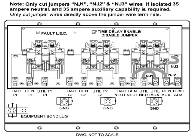
A shorting jumper at J5 or “Set Timer” (see wiring label) provides the capability to disable the time delay in the ATS 503 for use with alternate supply sources (such as an inverter) that do not need a time delay period. The default position for the shorting jumper is installed across “Timer On”. LED “TMR ON” will illuminate when the shorting jumper is bridging the pins at “Timer On”. LED “TMR ON” will not illuminate when the shorting jumper is bridging the pins at “TIMER OFF”.
Please note: If the shorting jumper is lost, the time delay will default to “TMR ON” and provide the time delay function, however the “TMR ON” LED will not illuminate.
FAULT LOCKOUT INDICATOR (“Generator” source side)
A fault lockout indicator LED (see wiring label for location) is provided to indicate that a fault has occurred in the system such as a relay failure.
If the ATS 503 is in generator mode when a fault occurs, all relays are forced back to shore line connections and the fault indicator LED illuminates. If a fault is detected prior to switching the fault indicator will turn on and the unit will not switch. In the event that the fault lockout indicator comes on do the following: Turn off the generator or alternate power source for a minimum of 1 minute. After one minute turn on the generator/alternate power source. If the fault lockout indicator comes back on, repeat the above steps. If the fault lockout indicator comes on three or more times consecutively contact a reputable RV service center. 5
LED INDICATORS
When operating from a Generator or Alternate source input, additional LEDs on the logic circuit board indicate:
- Low-voltage power supplies are operational
- Green LEDs D4 & D6 indicate relays are in shore line position
- Yellow LEDs D5 & D7 indicate relays are in “Generator” position
MOUNTING LOCATION
The ATS 503 is designed for indoor use only.
- DO NOT mount in harsh environments; avoid areas where high levels of dust, dirt, or moisture may occur.
- DO NOT mount in the same compartment as batteries or other flammable materials such as gasoline.
The ATS 503 is designed for horizontal mounting to a deck or floor. Vertical mounting may be used if the conductor entry into the switch is horizontal to the floor. - DO NOT mount upside down.
Leave adequate room for routing the shore line, generator and load (breaker panel) conductors. Use appropriately rated conductors for field installed wiring. Install strain relief fittings on all field installed wiring to provide adequate wire protection and support. Two combo knockouts are provided (1 on each side) for trade sizes ½” and ¾”.
Conductor entry openings at the front of the ATS503 are sized for 1 inch (2) and 1.25 inch (1) trade size strain relief fittings.
Wiring Diagram
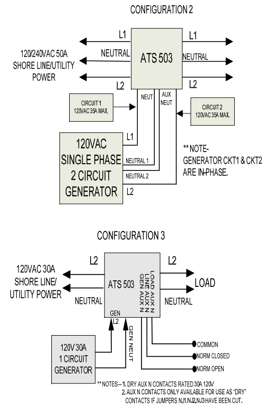
Examples Only! – Refer to the wiring diagram for wiring information.

Setup Guide
To set up the Parallax Power Supply Generator Transfer Switch ATS 503, follow these steps:
- Ensure the switch is installed by a licensed electrician to meet local electrical codes and safety standards.
- Connect the main power supply to the designated input terminals.
- Connect the backup generator to the generator input terminals.
- Configure the ATS settings using the provided user interface or smartphone app.
- Perform a test run to ensure the switch operates correctly between the main power and the backup generator.
Refer to the user manual for detailed instructions and safety precautions.
GENERAL INFORMATION
The ATS 503 is designed to switch the on-board 120-volt appliances to an alternate 120VAC power source such as an inverter or generator when the alternate power source is energized.
The ATS 503 features include a rugged galvanized steel enclosure, solid state printed circuit board construction, heavy duty PCB mounted relays, a 20-30 second generator time delay, time delay Enable/Disable, and compression lug wiring terminals with 5/32” hex drive set screws for ease of wiring and safe, reliable operation.
The default power source is the shore line or utility power input “side” of the switch.
The alternate power source or “Generator” input side of the switch will “take command” of the switch when the alternate source is energized.
Refer installation and servicing of this product to qualified service personnel. Technical or service information is provided solely for use by licensed electricians and certified RV technicians. No endorsement of technical expertise is expressed and/or implied. User assumes all liabilities arising from use of this information.
WIRING INSTRUCTIONS
WARNING: RISK OF ELECTRICAL SHOCK OR BURNS.
Note: If using the ATS 503 in a single phase 120VAC supply system, use connection terminals L2 and neutral for source input and load output connections. Generator side transfer will not occur if generator input terminals L2 and neutral are not energized.
- Utility L1, Utility L2, Utility Neut., and Utility Aux are input terminals for connection to Shore line/ Utility power.
- Gen L1, Gen L2, Gen Neut., and Gen Aux are input terminals for connection to the Generator or an alternate power source.
- Load L1, Load L2, Load Neut., and Load Aux are output terminals for connection to the load panel or load circuits.
- Jumpers NJ1, NJ2, and NJ3 bridge neutral and auxiliary terminals at each source input and at the load output to provide 70 ampere neutral return ampacity for use with “in-phase” 120VAC supply sources.
ALL CONNECTIONS MUST MEET TORQUE SPECIFICATIONS SHOWN ON THE WIRING LABEL LOCATED ON THE ATS 503 INSIDE COVER OR AS LISTED BELOW.
Terminal Torque Specifications
BONDED EQUIPMENT GND. CU 6-14; COPPER WIRE ONLY.
TORQUE RATING: 35 IN. LBS.
ALL OTHER TERMINALS TORQUE RATINGS:
| AWG | INCH-POUNDS |
|---|---|
| 10 – 14 | 35 |
| 8 | 40 |
| 4 – 6 | 45 |
| 2 | 50 |
FIELD WIRING CONDUCTORS INSULATION RATING 90°C, MINIMUM.
COPPER WIRE ONLY.
WIRE SIZE OF FIELD WIRING CONDUCTORS USE AMPACITY OF WIRE RATED AT 75 °C. MAXIMUM.
WARNING: RISK OF ELECTRICAL SHOCK OR BURNS.
No user-serviceable parts inside.
Refer installation and servicing to qualified service personnel
Troubleshooting
If you encounter issues with the Parallax Power Supply Generator Transfer Switch ATS 503, here are some common problems and solutions:
- Failure to switch to backup generator: Check the connections between the main power supply, generator, and the ATS. Ensure all settings are correctly configured.
- Indicator lights not functioning: Verify that the LED lights are not damaged and that the switch is receiving power.
- Remote monitoring issues: Ensure your smartphone app is updated and that you have a stable internet connection.
Always refer to the user manual or contact customer support for detailed troubleshooting guides and safety instructions.
Transfer Switch ATS 503 Pros & Cons
Pros
- Seamless automatic transfer between main power and backup generator
- Robust and weather-resistant design
- Advanced sensing technology for rapid power outage detection
- Remote monitoring and control capabilities
- Compliant with safety and performance standards
Cons
- Potentially higher cost compared to basic transfer switches
- Requires professional installation
- Dependent on stable internet connection for remote monitoring
Customer Reviews
Customers have praised the Parallax Power Supply Generator Transfer Switch ATS 503 for its reliability and ease of use. Many have noted the quick response time during power outages and the convenience of remote monitoring. However, some users have mentioned the higher cost and the need for professional installation as drawbacks.
Common complaints
Include occasional connectivity issues with the smartphone app and the need for more detailed user manuals.
WARRANTY INFORMATION
Reference the enclosed Parallax Power Supply Warranty Policy or download the policy at: http://www.parallaxpower.com/warranty
Faqs
What is the maximum power capacity of the Supply Generator?
Is the Parallax Switch compatible with all types of generators?
How does the remote monitoring feature work on the Generator Transfer Switch?
What are the safety standards that the Generator Transfer Switch complies with?
How long does it take for the Parallax Power Supply to switch to the backup generator during a power outage?
Is the Parallax Power Supply suitable for outdoor use?
Can I use the Parallax Power Supply ATS 503 with solar power systems?
What kind of maintenance is required for the Generator ATS 503?
Is there a warranty provided with the Parallax Power?
Leave a Comment
