Powerbass AutoSound Class D Ampifier ACS-500.2D User Guide

Content
Introduction
The PowerBass AutoSound Class D Amplifier ACS-500.2D is a compact yet powerful amplifier designed to deliver exceptional audio performance with 500 watts RMS at 2 ohms. This mono-block amplifier features a high-efficiency Class D design, ensuring minimal heat generation while maximizing output. With a variety of inputs and adjustable settings, including a variable low-pass crossover and bass boost EQ, it provides versatility for any audio setup. The cost of the ACS-500.2D is approximately $179.99.
SPECIFICATIONS
Two Channel Models | ACS-500.2D |
Power Output @ 14.4 VDCInput |
|
4 Ohms RMS Power (Watts) | 300 x 1 |
2 Ohms RMS Power (Watts) | 500 x 1 |
1 Ohm RMS Power (Watts) | n/a |
Peak Music Power (Watts) | 1000 |
THD @ RMS Power | 0.5% |
Frequency Response | 10Hz - 250Hz |
S/N Ratio (EIA Rated) | >100dB |
Input Sensitivity | 0.25V - 6.0 Volts |
Crossover Slope | 12dB |
Low-Pass Crossover Freq. (Hz) | 30 - 250Hz |
Bass EQ (on/off) | 0/12dB |
Subwoofer EQ Freq. | 45Hz |
Fuses/ ATC Style | 25A x 2 |
Dimension (2.0” H x 7.1” W) | 9.7” L |
Dimension (50mm H x 180mm W) | 246mm L |
Important Notes:
Due to continuing improvements, these specifications are subject to change without any notice. Do not attempt to fix or repair this unit. Unauthorized repairs will void the manufacturer’s warranty.
TECHNICAL FEATURES
- High Efficiency Class D Design
- Mono Block Amplifier for Subwoofer
- High and Low Level Line Input
- MOSFET Power Supplies for High Power Output and Best Stability into Low Impedance Loads
- Soft Delay Remote Turn On/Off Circuit Eliminates Pops and Clicks
- Variable Low Pass Electronic Crossover
- Selectable Bass Boost EQ
- Self Diagnostic Protection Circuit with LED Status Indicator for; Impedance Over-load, Speaker Short Circuit, Thermal Overheating, and DC Output.
- 1-OHM Stable Operation with Extensive Output Power Increase (ACS-500D, ACS-1000D)
- 2-OHM Stable Operation with Extensive Output Power Increase (ACS-500.2D)
- Variable Gain Control
- Remote Level Control Port(for optional controller)
INSTALLATION EXPERIENCE
Installation of PowerBass mobile amplifiers requires detailed knowledge of electronics wiring and proper speaker impedance. We strongly recommend installation by an authorized PowerBass dealer. This Owners Manual only provides general installation and operation instructions. If you have any reservations about your installation skills, please contact your local PowerBass dealer for assistance.
IMPORTANT: This amplifier is designed for operation in vehicles with 12-volt Negative ground electrical systems only.
PREPARING FOR INSTALLATION
NOTE: The tools listed below may be required for basic installation
- An electric drill with bits
- Philips head and standard screwdrivers
- Wire strippers
- Crimping tool
- VOM (electronic volt ohm meter)
- Heat shrink tubing and heat gun
- Soldering iron
- Electronic (Rosen Core not Acid Core) Solder
INSTALLATION PRECAUTIONS
NOTE: Proceed only if you are a qualified installer, otherwise; see your Authorized PowerBass Dealer to professionally install this amplifier. Always wear protective eyewear when using tools.
- Turn off all stereo and other electrical devices before you begin.
- Disconnect the negative (-) lead from your vehicles battery.
- Locate all fuel lines, brake lines, oil lines, and electrical cables when planning the install.
- Make sure there is at least 2-inches (5 cm) around the air vents on the amplifier.
- When connecting ground points, make sure all paint is carefully scrapped away from the vehicle’s chassis and contact is make with bare metal.
- Use a utility knife to trim away fabric from hole locations before drilling or cutting.
- When running power cables through sheet metal, be sure to use grommets to properly insulate the metal edges from the wire insulation.
- If possible, use tubing through grommets.
MOUNTING THE AMPLIFIER
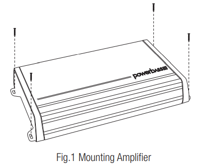
Due to the high power output of the PowerBass Autosound mono amplifiers, considerable heat may be produced when the unit is in operation. For this reason the amplifier should be mounted in a location which will allow air to circulate freely. A clearance of at least 2-inches (5 cm) to all sides of the amplifier is necessary not only for proper cooling, but also for gaining access to the inputs and other variable controls. Be sure that the power and signal cable connections can enter and leave the amplifier in a straight line to avoid the risk of kinked wires causing malfunction.
MOUNTING LOCATION
Find a clear and well ventilated area to mount your amplifier that is unobstructed by any objects that will cause harm or block ventilation. Despite the fact that this amplifier is compact, it still needs air to cool the heatsink fins. Do not mount under a carpet or an area with dead or stagnant air. Without proper air flow the amplifier may overheat and go into protection where the thermal overload circuitry will shut down the amplifier.
You may use the amplifier as a template and mark the four screw locations with a felt tip pen. Set the amplifier aside before drilling. Use caution to make sure there are no objects behind the installation surface that may become damaged during drilling.
The amplifier should be protected from exposure to moisture and direct sunlight. The best places to mount your amplifier are: The floor of the trunk, under the driver’s seat, or on the back of the rear seat. For alternate installation locations, please consult your authorized PowerBass Dealer.
NOTE: Do not use a drill with driver bit to mount the amplifier. Excessive force could cause the plastic mounting feet to crack.
WARNING
- Upside down mounting will compromise heat dissipation through the heatsink and could engage the thermal protection circuit.
- Try to avoid mounting the amplifier on a subwoofer enclosure, as extended exposure to vibration may cause malfunction of the amplifier.
- Don’t mount the amplifier so that the wire connections are unprotected or are subject to pinching or damage from nearby objects.
- The DC power wire must be fused at the battery positive (+) terminal connection. Before making or breaking power connections at the amplifier power terminals, disconnect the DC power wire at the battery end.
- The battery of the car audio system must be disconnected until the entire wiring and installation is completed.
- Don’t use a power drill to tighten the power, ground, remote or speaker output terminals on the amplifier to avoid stripping the terminal screws. It is best to hand tighten these connections.
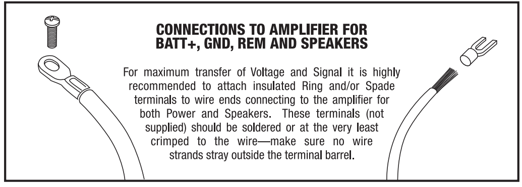
- The use of Ring and Spade terminals (not included) provides the best electrical connection for use with the clamp style connections on this amplifier.
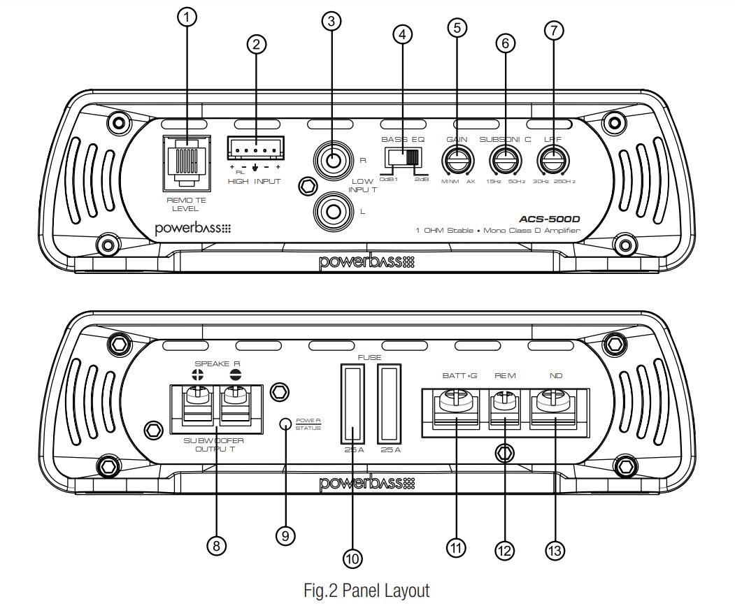
CONTROL PANEL LAYOUT
NOTE: Panel Layout and Controls may differ by model.
- REMOTE LEVEL PORT
This is the connector port for the optional Remote Gain Control. Now the amplifiers secondary gain circuit can be adjusted from the driver’s seat. Requires PB-GAIN1 accesory. - HIGH INPUT
Allows you to connect speaker output from factory radio to amplifier without the use of a low level convertor. - LINE IN (RCA) Jacks
These RCA style input jacks are for use with source units that have RCA line level outputs. A source unit with a minimum output of 250mV is required for proper operation. However, this input will accept levels up to 6Vrms. - BASS EQ Switch
This equalization circuit is used to enhance the low frequency response of the vehicle’s interior. Selectable for 12dB of boost centered at 45Hz, the BASS EQ can be adjusted to meet your own personal taste. - GAIN Control
This control is used to match the input sensitivity of the amplifier to the particular source unit that you are using up to 6 volts. - SUB SONIC Control
This control is continuously adjustable from 15Hz through 50Hz at 12dB per octave to provide an extra level of subwoofer protection from bass robbing power at unheard frequencies. - LPF (Low Pass Filter) Control
This filter controls low pass of frequencies and is adjustable from 30Hz through 250Hz to eliminate unwanted high frequencies. - SPEAKER Output Terminals
As shown in the wiring diagrams, be sure to observe speaker polarity through the system and speaker impedance. The clamp style wire terminal is designed to accommodate up to 10 gauge speaker wire (#8 spade). - POWER/STATUS Indicator
The clear LED turns BLUE when the power is on. Should the LED turn RED this is an indicator there is a problem with the system in relation to the amplifer - FUSES
For convenience most PowerBass AutoSound amplifiers utilize common automotive ATC type fuses. For continued protection in the event that a fuse blows, replace the fuse only with the same value.
CAUTION: These power fuses on the amplifier chassis are for protecting the amp against over current situation. To protect the vehicles electrical system, an additional fuse should be used within 18-inches of the battery on the 12V+ cable. [ACS-500D (25A x 2)] [ACS-1000D (35A x 3)] [ACS-500.2D (25A x 2)] - BATT+ (Power Input Terminal)
This terminal is the main power input for the amplifier and must be connected directly to the positive (+) terminal of the car battery. The clamp style wire terminal is designed to accommodate up to 4-gauge wire (#10 ring). See Power Cable Selection Chart for recommended wire gauge for each model. - REM (Remote Input Terminal)
All PowerBass AutoSound amplifiers can be turned on by applying 12 volts to this terminal. This can be found on the rear of the source unit in the form of a remote output. If this is not available you can wire to the ACC position on the key. An 18 gauge wire is sufficient to run the REMOTE. - GND (Ground Input Terminal)
A good quality ground is required for your PowerBass AutoSound amplifier to operate at peak performance. A short length of cable the same gauge as your power cable should be used to attach the ground terminal directly to the chassis of the vehicle. The clamp-style wire terminal is designed to accommodate up to 4-gauge wire (#10 ring). Make sure that all of the paint is sanded or scraped away to ensure a quality ground connection
Description
PowerBass ACS-500.2D is engineered with quality components to deliver superior sound reproduction. Its compact design makes it easy to install in tight spaces, while the robust cooling system ensures continuous operation without overheating. The amplifier features adjustable crossovers, allowing you to fine-tune the sound output to your preferences.
The unit includes multiple protection features such as overheat, overload, and short circuit protection, ensuring the longevity of the amplifier and connected components. With its sleek design and durable construction, this amplifier is a reliable choice for any car audio enthusiast.
POWER WIRING AND SIGNAL CONNECTIONS
WARNING
Disconnect the negative (-) battery terminal before you start any wiring work! The bat-tery of your car audio system must be disconnected until the entire wiring installation is completed.
Your PowerBass Autosound Mono amp will draw large levels of current, so use the largest gauge power/ground cable possible. Using too small of power cable can result in unnecessary over-heating of the ampli-fier, distortion at high volume levels and might even cause the thermal protection circuitry to shut-off the amplifier. Remember, bigger wire is better! For best results we recommend a PowerBass amplifier install kit, available at your local PowerBass dealer.
- Use rubber grommets when running cables through any metal or sharp plastic, to prevent accidental shorting or shearing. Make sure the cables do not interfere with normal operation of the vehicle.
- The audio signal cables (RCA interconnects) should be kept far away from any potential sources of electrical interference such as electronic vehicle management systems (relays, engine computers wiring harnesses, fuel pumps etc.)
This amplifier is designed to work within a 9 to 16 volt DC range. Before any wires are connected, the vehicles electrical system should be checked for correct voltage supply with the help of a voltmeter.
First, check the voltage at the battery with the ignition in the OFF position. The voltmeter should read no less than 12V. If your vehicles electrical system is not up to these specifications, we recommend having it checked by an auto electrician before any further installation. Once the vehicle is checked, make certain the correct cable gauge is used. We recommend using as large a gauge cable as possible, use the Power Cable Selection Chart to calculate the correct power wire size for your application. Remember Bigger is Better!
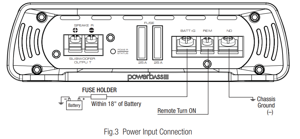
BATT+ (Power)
This amplifier should be wired directly to the vehicle battery using the appropriate size cable. Start at the vehicle battery and run the power cable through to the amplifier. Avoid running the power cable over engine components and near heater cores. The use of an inline fuse or circuit breaker is a must; this will prevent the risk of a potential fire caused by a short in your power cable.
Connect the fuse holder or circuit breaker as close to the battery positive (+) terminal as possible (no farther then 18” from that battery). This fuse or circuit breaker should be no greater then the sum of the fuses found on the chassis of your amplifier (also see specifications chart). You may now connect the cable to the battery, but remember to leave the fuse out or circuit breaker “off” until all other cable connections are made.
GND (Ground)
When grounding your amplifier, locate a metal area close to the amplifier that is good source of ground (preferably the floor pan). Once again, investigate the area you wish to use for electrical wires, vacuum lines, and brake or fuel lines. Use either a wire brush or sandpaper to eliminate unwanted paint for better contact of the ground.
Secure the ground cable to the body using a bolt, star washer and nut. Spread silicon over the screw and bare metal to prevent rust and possible water leaks.
_powerbass_autosound_class_d_amplifier_acs-500.2d.png)
Now it’s time to connect the power and ground cables to the amplifier. Cut both cables to length. Use a Philips screwdriver to loosen the BATT+ and the GND connections on the amplifier. Insert the ground first, and then the +12V and please make sure that you place them into the correctly marked terminals. Then tighten the screws down securely.
REM (Remote Trigger)
This terminal must be connected to a switched +12V source. Typically, remote turn-on leads are provided at the source unit that will turn on and off the amplifier in correspondence with the source. If the source unit does not have a remote turn-on lead, then a switched +12V supply must be used, like the ACC, +12V.
Run a minimum of 18 gauge wire from the amplifier location to the source of the switched +12V lead. If possible, route this wire on the same side of the vehicle as your power cable. Connect the source remote output to the wire. Go back to the amplifier and cut the wire to length. Loosen the screw terminal marked REM on the amplifier.
FUSE REQUIREMENTS
While the panel on your PowerBass amplifier incorporates one or more fuses, these do nothing to protect the vehicle from a dangerous short circuit. It is absolutely vital that the main power lead to the amplifier(s) in the system be fused within 18-inches (45cm) of the connection to the vehicle battery. The value of this fuse (or circuit breaker) should be no greater than the sum of the fuses found on all of the equipment being connected to that power wire.
NOTE: It is highly recommended that a hand screw driver and NOT a power drill is used to tighten the screws on the terminal blocks. This will prevent stripping or other possible damage to the amplifier.
RCA INTERCONNECT WIRING
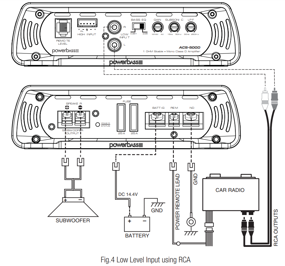
- Choose the correct length and style of RCA interconnects for your needs. Always use high quality RCA audio cables (not supplied) for signal connections—those with multiple layers of shielding or a twisted pair variety provides better noise rejection.
- Be extra careful when routing your RCA audio interconnect cables. Car environments are notorious for poorly insulated wires. This means that hiss, engine noise, and fan noise can easily be picked up through RCA cables if run incorrectly.
- Make sure that the cables for power and audio signal are not on the same side of the vehicle and that they do no cross each other; this will help reduce any noise that may radiate from the power cable and the signal cable. If an audio cable is too close to a power cable, it may pick up the magnetic field generated by the power cable, which could lead to a loss of quality in your signal.
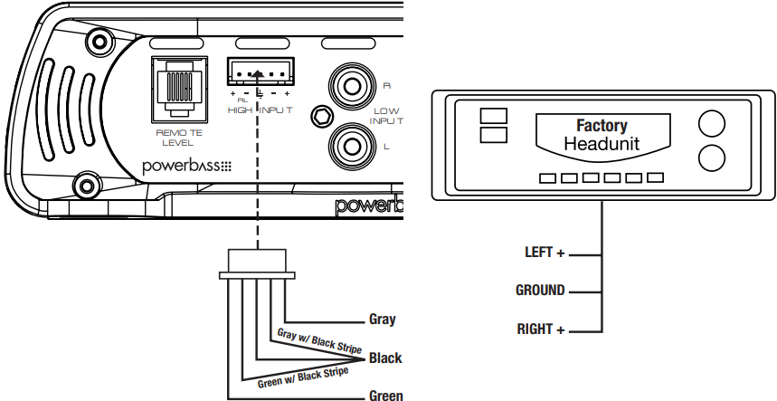
HIGH-LEVEL CONNECTIONS (Optional)
High-Level inputs have been included to connect the amplifier to a radio without low-level outputs (i.e. factory radio). This connection will allow you to connect directly to the speaker output of the radio without the need of an external adapter.
Determine the type of radio you have and make one of the following connections. Do not use the High Level inputs if you have already wired the Low Level Inputs.
CAUTION! Before making any connections determine the type of radio to avoid possible damage to amplifer and/or radio.
TWO CHANNEL CONNECTIONS: FLOATING GROUND RADIO (MOST COMMON TYPE)
_powerbass_autosound_class_d_amplifier_acs-500.2d.png)
TWO CHANNEL CONNECTIONS: COMMON GROUND RADIO (RARE TYPE)
SET UP ADJUSTMENTS
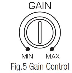
Input Gain Adjustment
This control allows you to match the input level of the amplifier to the output level of your head unit. Matching the input can be accomplished in four simple steps:
- Make sure that the remote gain control is not plugged in until after the master gain control is set.
- Set the GAIN control on the amplifier to Min (completely counter clock wise).
- Turn on the head unit and adjust volume to 2/3 maximum, and set the BASS and TREBLE to zero.
- Adjust the LEVEL control clockwise until the sound just begins to distort, then back off slightly to cut distortion and operate at optimum gain.
Remember, the GAIN control is not a volume control. Ignoring these four steps above may leave you with damaged speaker and/or a damaged amplifier.
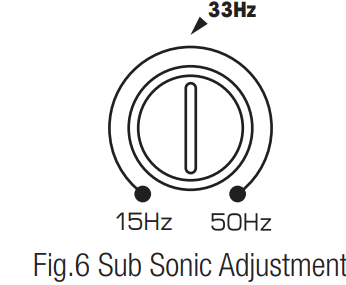
Sub Sonic Adjustment
The subsonic filter is a 12 dB/octave high-pass filter, with a fully variable cutoff frequency between 15 - 50 Hz. When set at frequencies lower than 33 Hz, it conserves amplifier power without audibly affecting the quality of the sub-bass output.
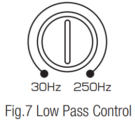
LPF (Low Pass Filter) Adjustment
The crossover frequency adjustment filters out frequencies that you don’t want your subwoofer(s) to repro-duce. Using the LPF control, adjust the Low Pass Frequency to limit the amount of mid range you want going to your subwoofer(s). Since musical tastes vary, adjust the crossover by ear while listening to the music of your choice. Be sure to set the tone controls of your source unit to flat before adjusting the crossover
_adjustment_powerbass_autosound_class_d_amplifier_acs-500.2d.png)
Bass EQ Switch
This special feature is designed to provide you more powerful sound quality, and it allows you to boost the Bass EQ to 12dB. Keep in mind that more is not always better. Setting the control to the max (12dB) will stress the amplifier and the speakers and could result in damage.
NOTE: More is not always better. By selecting 12dB you can overwork the amplifier and send the unit into thermal protection.
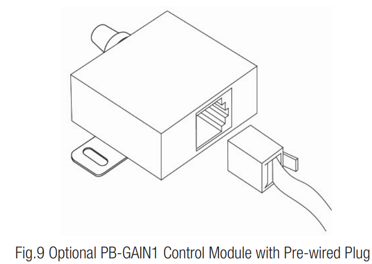
Remote Level Controller Connection (Optional)
A Remote Level control module is available separately, ask your dealer for model PB-GAIN1. It uses standard telephone wire and telephone RJ45 connectors. To connect the Remote Level Control to the amplifier, simply insert one end of the telephone plug into the REMOTE LEVEL port. Plug the other end into the remote module. Install the module within easy reach on or under your dash.
SPEAKER WIRING AND CONFIGURATIONS
Speaker Load
Keep in mind your PowerBass Autosound Class D amp is a high power amplifier and not a high current amplifier. 1-OHM minimum for ACS-500D and ACS-100D. 2-OHM minimum for ACS-500.2D Lower impedance will send the amplifier into protection and possibly damage the electronics inside.
Subwoofer Wiring
- Choose the correct speaker wire for your application. We recommend a minimum of 16 gauge wire. Route these using the same precautions as you did when you ran the power cable. Terminate these wires at the subwoofer end using insulated speaker terminals (not supplied) or by soldering the connection to the sub-woofer. Be certain to maintain correct polarity throughout the system.
- Make sure the subwoofer connections are positive-to-positive and negative-to-negative. Most speaker wire has some indicator (color code, ribbing, or printing) on one of the two wires to help you distinguish the positive (+) and negative (-) leads.
- At the amplifier end, insert the speaker wires into the properly marked terminals. Use a Phillips screw driver to loosen the speaker terminals on the amplifier. Make certain that no bare wire ends touch each other. Such contact could result in an electrical short and cause the amplifier to turn off (short circuit protection) or malfunction.
- DO NOT attempt to “bridge” the speaker outputs of this amplifier with the speaker outputs of a second amplifier.
NOTE: It is highly recommended that a hand screwdriver and NOT a power drill is used to tighten the screws on the terminal blocks. This will prevent stripping or other possible damage to the amplifier.
SPEAKER OUTPUT CONFIGURATIONS
ACS-500D, ACS-1000D
1-OHM STABLE DESIGN Minimum Impedance Load is 1-OHM
A SINGLE VOICE COIL SUBWOOFER SPEAKER

TWO SINGLE VOICE COIL SUBWOOFER SPEAKERS

ONE DUAL VOICE COIL SUBWOOFER SPEAKERS


RECOMMENDED WIRE SIZES
| Power Cable Selection Chart | |||||||
| Fuse Total | 4Ft | 4-7Ft | 7-10Ft | 10-13Ft | 13-16 Ft | 16-19 Ft | 19-22 Ft |
| In Amperes | Length of Wire/Gauge | ||||||
| 150A - 200A | 2 GA | 2 GA | 2 GA | *1/0* | *1/0* | *1/0* | *1/0* |
| 125A - 150A | 4 GA | 4 GA | 4 GA | 4 GA | 2 GA | 2 GA | 2 GA |
| 105A - 125A | 8 GA | 8 GA | 8 GA | 4 GA | 4 GA | 4 GA | 2 GA |
| 85A - 105A | 8 GA | 8 GA | 8 GA | 4 GA | 4 GA | 4 GA | 4 GA |
| 65A - 85A | 10 GA | 8 GA | 8 GA | 8 GA | 4 GA | 4 GA | 4 GA |
| 50A - 65A | 10 GA | 10 GA | 8 GA | 8 GA | 8 GA | 8 GA | 8 GA |
| 35A - 50A | 10 GA | 10 GA | 10 GA | 8 GA | 8 GA | 8 GA | 8 GA |
PowerBass makes several types of amplifier wiring kits to assist with the installation of your PowerBass amplifier. Consult your local PowerBass dealer for details. For more information about recommended power wire check out our website at http://www.powerbassusa.com
PowerBass AutoSound Class D Amplifier Troubleshooting
| Problem | Solution |
| Power LED not ON | With a Volt Ohm Meter (VOM) check: • +12 Volt power terminal (should read +12 to +16VDC • Remote turn-on terminal (should read +12 to +16VDC) • Ground Terminal |
| Power LED lights BLUE, no output | • Check RCA connections • Test speaker outputs with known good speaker • Substitute known good Source Unit • Check for signal on the RCA cable with VOM in AC position |
Red Status Protection LED is ON, no output and 1. Amp is VERY HOT
2. Amp shuts down ONLY when the vehicle is running
3. Amp plays at very low volume |
• Thermal protection is engaged. Check for proper impedance at speaker terminals. Also check for adequate air flow around the amplifier. • Voltage protection engaged. Voltage to the amp is not within the 10-16.5 VDC operating range. Have the battery/charging system inspected. • Short circuit protection is engaged.Check for speaker wires shorted to each other or the vehicle chassis. Speakers operating below the minimum impedance can cause this to occur. |
| Alternator noise (varies with RPM) | • Check for damaged RCA cable. • Check routing of RCA cable • Check Source Unit for good ground • Check amp gain setting, turn down if set too high • Check for chassis Ground short on speakers |
| Poor Bass Response | Check woofer polarity, reverse the connection of one speaker only. |
NOTE: If the Status L.E.D. is activated and glows RED with no speakers connected to the amplifier, and all the power connections are correct, this would indicate an internal problem with the ampli-fier. Contact PowerBass USA or your local dealer.
Pros & Cons
Pros
- High Efficiency with Low Heat Generation
- Compact Design for Easy Installation
- Robust Power Output with Clean Sound Quality
- Adjustable Crossover Settings for Customization
- Multiple Protection Features for Reliability
Cons
- Higher Price Point Compared to Other Brands
- Requires Proper Installation to Avoid Overheating
- Slightly Complex Setup for Beginners
Customer Reviews
Customers have generally praised the PowerBass AutoSound Class D Amplifier for its performance and durability. Many have noted the significant improvement in sound quality and the ease of installation despite its compact size. However, some users have mentioned that it requires careful setup to avoid overheating issues.
Common complaints include the higher price point compared to other amplifiers on the market and the need for a detailed understanding of car audio systems for optimal setup.
WARRANTY POLICY
PowerBass Autosound Amplifiers are to be free of defects in material and workmanship for a period of one (1) year.
Faqs
What is the power output of the PowerBass AutoSound Class D Amplifier?
What are the key features of this amplifier ACS-500.2D?
How do I set up the PowerBass AutoSound Class D Amplifier?
Why is my PowerBass AutoSound Class D Amplifier not turning on?
How do I prevent overheating issues with my PowerBass AutoSound Class D Amplifier?
Can I use this amplifier with any car audio system?
What are some common problems and solutions for this amplifier?
Are there any specific warnings or precautions when using this amplifier?
What do customers generally say about this amplifier?
Leave a Comment