
Setup: Profi Pumpe FLOW SWITCH User Manual
Content
profi pumpe FLOW SWITCH
Introduction
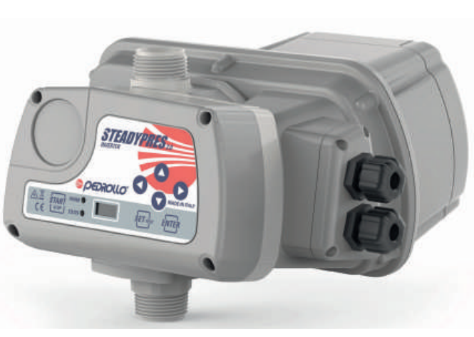
The profi pumpe FLOW SWITCH is a reliable, intelligent solution for monitoring and controlling water flow in a wide range of residential, commercial, and industrial applications. Designed for non-abrasive, clear water systems, this flow switch offers advanced opto-electronic sensing technology, ensuring precise detection and automatic pump control. Whether you're managing irrigation, water supply, or pump protection, the profi pumpe FLOW SWITCH delivers unmatched reliability and safety.
Key benefits include high sealing, complete isolation of live parts from water pipes, and an integrated design that simplifies installation and reduces material costs. The device can replace traditional pressure switches, water protection devices, and check valves, making it a versatile upgrade for any water system. Its robust IP65 protection grade ensures durability in demanding environments.
Target users include plumbers, facility managers, and homeowners seeking efficient, automated water management. The profi pumpe FLOW SWITCH is widely available through authorized distributors and online retailers, with an estimated price range of €80–€120, offering excellent value for its advanced features and long-term reliability.
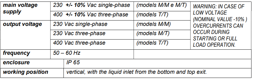
Specifications
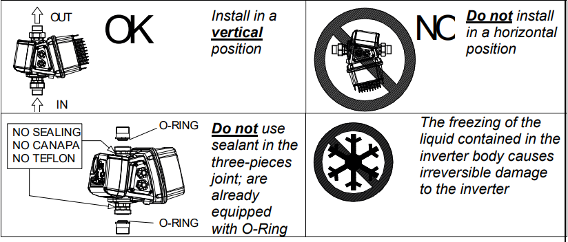
Install the inverter in a place:
- protected from the elements
- ventilated, free from excessive humidity or excessive dust
- as close as possible to the pump
- Make sure that it does not receive harmful vibrations or mechanical stress from connected pipelines
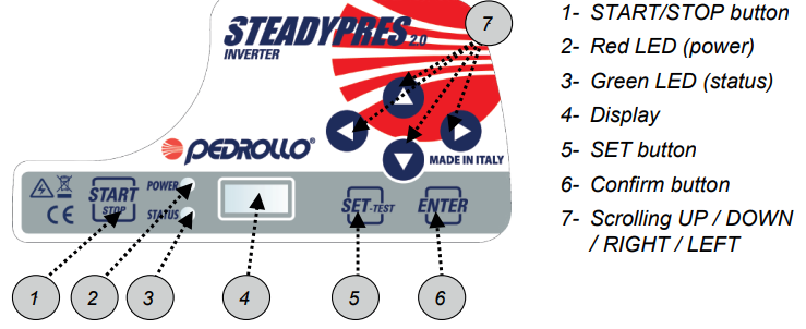
Control panel:
INSTALLATION AND HYDRAULIC CONNECTIONS
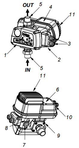
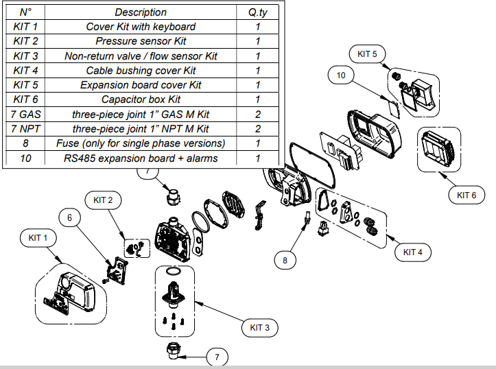
PART LIST
- control system
- removable electric connector
- I/O power cable bushing
- power board cover
- three-piece joint
- tTecnicadata plate
- n.a.
- fuse (not present in T/T models)
- non-return valve unit
- expansion board cover
- capacitors box
NOTE: the inverter supply line must be protected by suitable devices in conformity with applicable standards.
In applications in parallel,
- there is a MASTER inverter that controls one or two SLAVE inverters.
- The MASTER receives the programming of the parameters and controls the operating data, and activates and deactivates the SLAVE as needed.
- If the MASTER is turned off, the SLAVE goes back to being self-employed and will continue to operate independently
- When working in parallel with other inverters, STEADYPRES controls the alternation of starting to make the use of the pumps uniform.
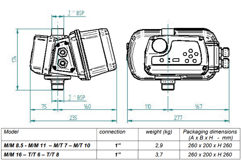
DIMENSIONS AND WEIGHTS
INSTALLATION
Before installing and using STEADYPRES:
- Read this manual thoroughly and carefully, and refer to the Safety Standards.
- Before making the connections, make sure that the ends of the line wires are not live.
- Make sure also that the electric power supply network is protected by thermal magnet and differential protections according to the applicable Standard in force. The differential switch must be a high-sensitivity type (30 mA in class A for domestic applications, class B for industrial applications)
- Ground connections must be in compliance with Standards.
- Check that the plate data is what is required and suitable for the system
- The cable section (power supply cable and connection cable between the inverter and the motor) must be dimensioned according to:
- Voltage (230 V single-phase, 230 V three-phase, 400 V three-phase)
- Pump power
- Cable length
- The power supply cable and the motor cable must be sized to curb any power voltage drop within 3%.
- The power supply cable and the motor cable must be suitably shielded to comply with EMC standards.
- In case of long cables between the Inverter and the pump motor, evaluate the application of the inverter output sinusoidal filter. It aids the smooth running of motors, eliminating the negative effect of voltage peaks.
STARTING UP
- Before running, this Manual must have been carefully read and the instructions followed; wrong settings and operations are thus prevented that could cause operating faults.
- Before starting the system, the pumps must be primed (filling and air bleeding)
- After performing the operations described in the INSTALLATION chapter, the inverter can be started.
- When STEADYPRES is switched on, it enters the STARTING phase, which lasts 10 seconds, after which STEADYPRES returns to the same operating conditions in which it was when it was last switched off :Inn WORK mode if at the time of the last shutdown it was IN SERVICE
- in OUT OF SERVICE mode if at the time of the last shutdown was OUT OF SERVICE (OFF)
- In case of accidental fall of the power line, if it STEADYPRES was in service, when the power returns, it automatically returns in service
- To put STEADYPRES IN SERVICE / OUT OF SERVICE, press the START / STOP button.
- In applications with parallel inverters (MASTER / SLAVE) is just the MASTER inverter that receives input from the keyboard - SLAVE inverters operate independently only if the MASTER is turned off, in which case they receive input from their own keyboard.
- In each group can be only one MASTER, one SLAVE 1, and one SLAVE 2.
- In normal operation, you can view the status parameters.
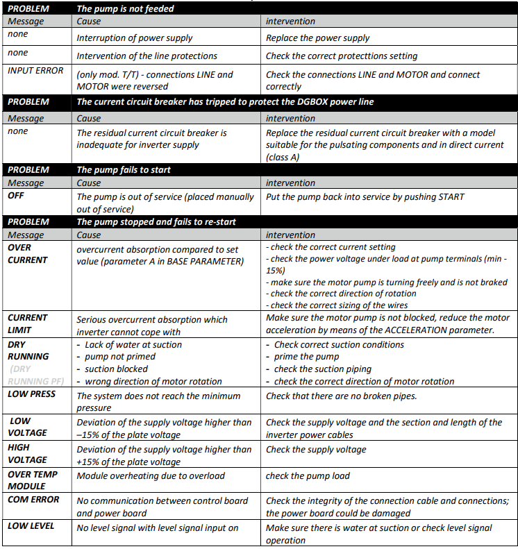
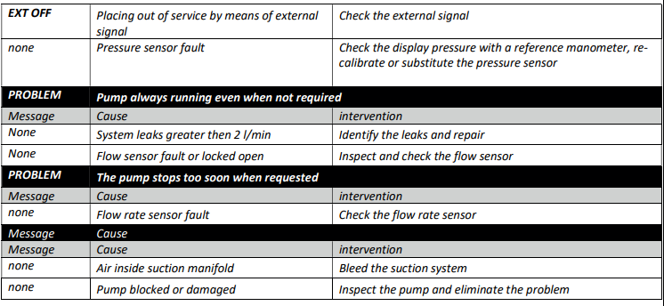
Troubleshooting: Profi Pumpe FLOW SWITCH
MAINTENANCE
Replacement of the CONTROL BOARD + PRESSURE SENSOR
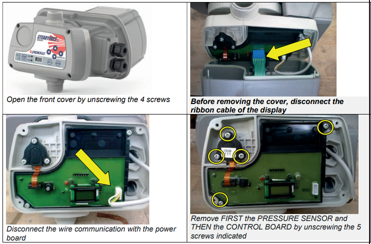
- Disconnect the inverter main power supply and wait 2 minutes (capacitors discharge)
- Open the front coveand r and anddisassembley the pressure sensor and the control board as shown below
- Install the new control board with the pressure sensor in the reverse order of removal.
SPARE PARTS DIAGRAM
WARRANTY
Before installation and use of the product, read this manual completely and thoroughly. Installation and maintenance must be carried out by qualified staff, responsible for performing the hydraulic and electric connections according to the applicable Standards in force.
The manufacturer declines all responsibility for damage deriving from improper use of the product and is not liable for damage caused by maintenance or repairs that are carried out by unqualified staff and/or using non-original spare parts. The use of non-original spare parts, tampering, or improper use makes the warranty null and void.
Pros & Cons Profi Pumpepe FLOW SWITCH
Pros
- Advanced opto-electronic sensing for precise flow detection
- High safety with IP65 protection and live part isolation
- Easy installation and integration with existing systems
- Replaces multiple traditional components, saving space and cost
- Reliable performance in residential and light commercial applications
Cons
- Limited to clear, non-abrasive water (not suitable for dirty or slurry applications)
- The maximum water temperature of 35°C may restrict use in hot water systems
- Single-phase only; not compatible with three-phase pumps without additional circuit protection
The profi pumpe FLOW SWITCH offers excellent value for money, especially for users seeking a modern, automated solution for water flow monitoring and pump control.
Customer Reviews: Profi Pumpe FLOW SWITCH
Users consistently praise the profi pumpe FLOW SWITCH for its reliability and ease of installation. Many highlight its ability to prevent pump dry runs and its robust build quality. Common complaints include the temperature limitation and the need for clear water. The device typically receives 4.5 out of 5 stars, with customers recommending it for residential water supply and irrigation systems. Frequent mentions include its long lifespan and minimal maintenance requirements.
Faqs
How do I properly install the profi pumpe FLOW SWITCH for optimal performance?
What should I do if the profi pumpe FLOW SWITCH is not activating the pump as expected?
Can the profi pumpe FLOW SWITCH be used with pumps over 10A current or three-phase pumps?
How do I switch between Quick-Stop and Normal-Stop modes on the profi pumpe FLOW SWITCH?
What maintenance is required to keep the profi pumpe FLOW SWITCH functioning reliably?
What water quality requirements are necessary for the profi pumpe FLOW SWITCH to operate correctly?
How can I adjust the cut-in pressure on the profi pumpe FLOW SWITCH?
What are common issues causing the profi pumpe FLOW SWITCH red status light to flash, and how can I resolve them?
Tags
Leave a Comment