
Usage: Reliance Controls Pro/Tran 2 Manual Transfer Switches Owner Manual
Content
Reliance Controls Pro/Tran 2 Manual Transfer Switches
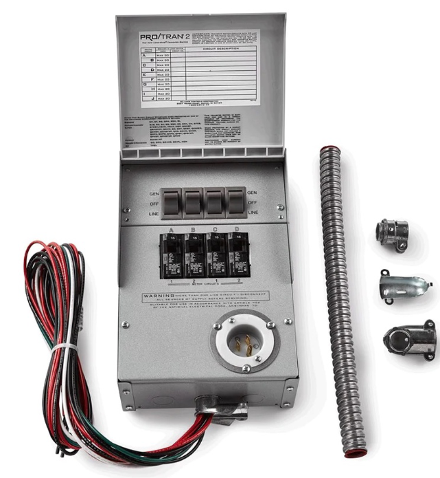
Introduction
The Reliance Controls Pro/Tran 2 Manual Transfer Switches are engineered to provide safe, reliable backup power to your home or business during an outage. These transfer switches are designed for seamless integration with portable generators, ensuring that critical circuits—such as lighting, refrigeration, heating, and medical equipment—remain operational when the grid goes down. With their user-friendly manual operation, robust construction, and UL-listed certification, Reliance Controls Pro/Tran 2 switches stand out as a top choice for emergency power management.
Key benefits include easy installation thanks to pre-wired circuits, color-coded wattmeters for load balancing, and flexible configuration options for both single- and double-pole breakers. These switches are compatible with any UL-listed 1” interchangeable circuit breaker, making them adaptable to various electrical setups. Their non-defeatable, break-before-make, double-throw switches ensure safe transitions between utility and generator power, protecting both your equipment and utility workers.
The target audience includes homeowners, small business operators, and contractors seeking a dependable, code-compliant solution for backup power. Typical use cases range from residential whole-house backups to selective circuit powering in offices, workshops, and retail spaces. The Reliance Controls Pro/Tran 2 Manual Transfer Switches are widely available through electrical suppliers, home improvement stores, and online retailers, with prices generally ranging from $300 to $600 depending on the model and number of circuits.
Whether you’re preparing for storm season or ensuring business continuity, the Reliance Controls Pro/Tran 2 Manual Transfer Switches deliver peace of mind, safety, and convenience in a single, rugged package.
Reliance Installation
Key Components of the Reliance Transfer Switch
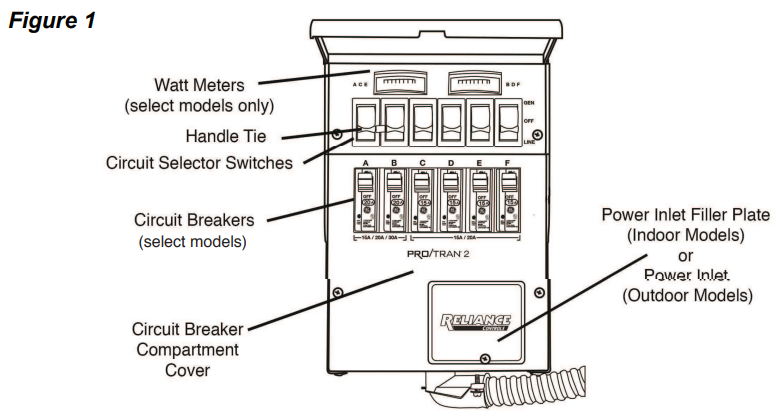
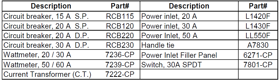
- Circuit breakers. Each transfer switch circuit has a 1-in interchangeable circuit breaker that protects the branch circuit when the circuit selector switch is in the GEN position. In the LINE position, each branch circuit is protected by the breaker in the load center. If you purchased a transfer switch that does not include the circuit breakers, you will need to purchase the appropriate UL 489 Listed breakers. A list of acceptable breakers can be found on the inside of the transfer switch cover.
- Circuit selector switches. These switches allow you to select either GEN (generator) or LINE (utility) as the power source for the branch circuits that have been wired through the transfer switch. The OFF position is generally not used, as a switch in the OFF position removes that branch circuit from both utility and generator power.
- Handle ties. Handle ties are used for 240-volt circuits or multi-wire branch circuits. They may be removed for 120-volt circuits. See page 6 for instructions on removing and adding handle ties. Power inlet filler plate. This can be replaced with a power inlet that is included in the suffix A and B models (see page 7 for installation instructions). The power cord from the generator is plugged into this inlet. The inlet is supplied separately for indoor models to encourage the use of a remote connection outdoors,, reducing the likelihood of running the generator indoors,, is whichis extremelyextremely dangerous. If this indoor model is installed outdoors, make sure it is installed in a dry location.
- Circuit Breaker Compartment Cover. Remove to change circuit breakers. Also includes a wiring space that can be used to hard-wire the unit to a remote power inlet box. Analog wattmeters (suffix A and C models). These meters indicate the total load, in watts, on each side of the generator when the generator is supplying power as follows:

Installation Instructions
You will need the following items:
- Electric drill
- Screwdriver
- Wire cutters/stripper
- Hammer
- Four anchors and screws
- 6 or 10 yellow wire connectors (depending on the model)
- 4 red wire connectors for the 20A and 30A hard-wire models
The following five steps generally apply to all transfer switch installations. The transfer switch may be installed on either side of the load center.
- Turn off the main circuit breaker in the load center to ensure your safety.
- Remove the cover of the load center.
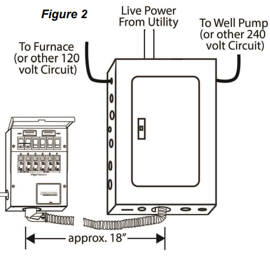
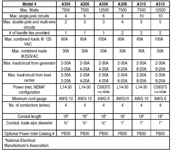
- Locate and remove a knockout (ko) at the bottom of the load center (Figure 2). Use a 3/4" ko for 6-circuit models, and a 1" ko for 10-circuit models.
- Insert the wires extending from the end of the flexible conduit through the ko. Attach the conduit connector securely with the locknut provided.
- Anchor the transfer switch to the wall using the top bracket and bottom mounting holes located in the cabinet behind the wiring compartment cover. Do not attempt to bend the flexible conduit beyond its structural capabilities.
Wiring the Reliance Transfer Switch to the Load Center
Determine which circuits will be used during an emergency. The residential wattage requirement chart on the inside front cover of this manual may be used as a guide, but actual appliance wattages may vary. If a selected circuit is part of a multi-wire branch circuit, ensure the other branch circuit that shares the neutral is also connected to the transfer switch. The two circuits must be connected to opposing legs (phases) of the generator power,, and a handle tie must be installed on the switch handles so that both legs are transferred at the same time.
Warning: Failure to properly install a multi-wire branch circuit could result in overloading the neutral wire.
The maximum number of circuits available and those that can be used for multi-wire branch circuits depend on the model of the transfer switch as follows:

Balancing the Load
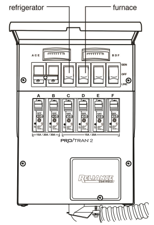
To maximize the efficiency of your generator, divide appliance circuits and others requiring higher wattage between adjacent circuit selector switches of the transfer switch so that a usage balance is achieved between the opposing legs of the generator power. For example, on a 6-circuit transfer switch, consider wiring the refrigerator to Switch C and the furnace to Switch D (Figure 3).
Changing Circuit Breakers
This product is wired for a combination of 15- and 20-amp circuit breakers,, and a 30-amp double-pole breaker may be installed in the A and B positions.
All circuit breaker positions will accommodate 15- and 20-amp circuit breakers, and may be easily changed in the field. To install/remove a circuit breaker, remove the circuit breaker compartment cover, unscrew the terminal screw in the breaker to be removed, remove the wire, tilt the top of the circuit breaker towards you, , and lift up and out. Reverse the procedure to install a new breaker. In addition, positions A and B (but only these positions) will accommodate 30-amp circuit breakers. This product is UL approved for use with the field-installed breakers listed on the side of the cabinet: Use 30 amps maximum in positions A and B, 20 amps maximum in all other positions. The rating of a transfer switch circuit breaker should not exceed the rating of the corresponding branch circuit breaker in the load center. Do not install any breaker larger than 20 amps., except in positions A and ,, B, which may be 30 amps.
Installing 120-volt Circuits
Warning: Transfer switch circuits with 20 amp breakers must be installed on only those branch circuits with 20 amp branch circuit breakers. Transfer switch circuits with 15-amp breakers can be installed on 15 or 20-amp branch circuits. Do not install any transfer switch circuit on branch circuits greater than 20 amps, except in positions A and B,, which may be 30 amps.
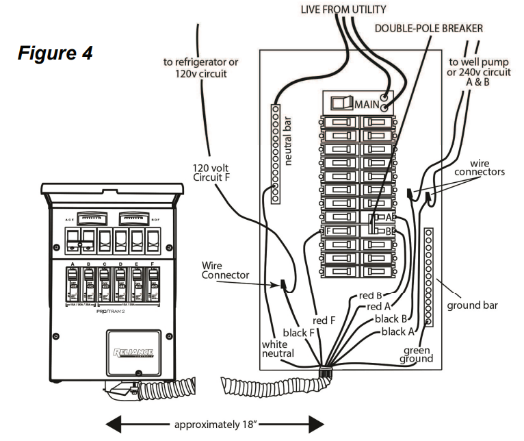
Wire the most critical circuits first, starting with any circuit position on the transfer switch. Let's assume that Switch C will be designated to supply power to the refrigerator.
- Turn off the refrigerator circuit breaker. Loosen the screw that secures the wire to the circuit breaker. Disconnect the wire from the circuit breaker.
- On the transfer switch, find the black and red wires marked C.
- Feed the red wire to the selected breaker, in this case,, the refrigerator breaker.
- Cut the red wire C to a convenient length. Strip approximately 5/8" from the end of the wire. Connect the red wire to the refrigerator circuit breaker and retighten the screw.
- Cut the black wire C to a convenient length for aligning with the wire removed from the refrigerator circuit breaker in step 1. Strip approximately 5/8" from the end of the wire.
- Insert both wires (the wire removed from the circuit breaker in step 1 and the black wire) into a yellow wire connector. Twist the connector tightly and push the wires back into the wiring compartment of the load center.
- This completes the installation of the transfer switch for your refrigerator. Repeat steps 1-6 for each of the remaining,, consideringg the following:
- See the following section for 240-volt circuits and the removal of handle ties if 240-volt circuits are not required.
- Remember to "balance the load"—dividing the appliances requiring higher wattage between the left and right sides of the transfer switch.
Installing 240-volt Circuits
Any two adjacent circuit selector switches may be used for a double-pole 240-volt circuit. Use a handle tie to connect the two circuit selector switches.
Note: Circuits used for multi-wire branch circuits are not available for 240-volt circuits
Removing handle tie(s). If there are no 240-volt or multi-wire circuits in the transfer switch installation, handle-ties on the switches are not needed. To remove a handle tie, place the handle-tied switches in a position opposite to the other switches. Rotate the cylindrical spacer between the switches upward repeatedly until the threaded shaft is exposed on the right switch. Grab the threaded shaft and continue to rotate the spacer upward until the spacer is free, being careful not to drop the spacer when it becomes free. Remove the shaft from the switch. If the shaft is not exposed after several revolutions of the spacer, insert a small slot screwdriver in the hole in the right switch and continue rotating the spacer upward while the screwdriver prevents the shaft from rotating. Adding handle ties. If additional ties are needed to accommodate an additional 240-volt
or multi-wire circuits, they can be added to adjacent pairs of switches.
Warning: Transfer switch circuits with 20 amp breakers must be installed on only those branch circuits with 20 amp branch circuit breakers. Transfer switch circuits with 15-amp breakers can be installed on 15 or 20-amp branch circuits. Do not install any transfer switch circuit on branch circuits greater than 20 amps, except in positions A and ,,,, B,, which must, be 30 amps.
Installing 240-volt circuit(s)
- Locate the two red and two black wires from any adjacent circuit positions.
- Turn off the double-pole breaker in the load center.
- Loosen the screws that secure each wire to each circuit breaker. Disconnect the wires from the circuit breakers.
- Feed the two red wires in Step 1 to the double-pole circuit breaker. 5. Cut the red wires to a convenient length. Strip 5/8" from the end of each wire. Connect the two red wires to the double-pole circuit breaker.
- Cut the black wires to a length convenient for aligning with wires r
- Removed from the circuit breaker. Strip 5/8" from the end of each wire.
- Insert one wire removed from the circuit breaker and one black wire into a yellow wire connector. Twist to tighten and push the wires back into the wiring compartment of the load center. Do the same for the other wire removed from the circuit breaker and the other black wire from the transfer switch.
- Be sure that a handle tie is connected between the two circuit selector switches.
Repeat steps 1-8 for the other double-pole circuits.
- 30-Ampere Circuits. Only circuits A and B may be used for 30-amp. Circuits. Follow the above wiring instructions for installing 240-volt circuits. If 30-amp. Single-pole circuits are being used; refer to the previous section regarding the installation of 120-volt circuits.
- For models with a C or D suffix, or to hard-wire any cord-connected model, continue to the next section entitled "Hard-wire Installation" to complete the installation.
- For models with an A or B suffix,, skip to "Inlet Installation for Indoor Models Used Outdoors" on page 7.
Hard-wire Installation
"Hard-wire" installation to a power inlet box located remotely from the transfer switch (Figure 5) requires additional steps to complete the installation. The wire connections to the wires frothe m the power inlet box are made in the circuit breaker compartment of the transfer switch. Access the circuit breaker compartment by removing the two screws located on the sides of the lower circuit breaker compartment cover. Replace when installation is complete.
From the transfer switch, connect:
- The black wire leads to the power inlet X or Y terminal
- The white wire leads to the power inlet neutral W terminal, the red wire leads to the power inlet X or Y terminal T. hee green wire leads to the power inlet ground G terminal.
Inlet Installation (For indoor models installed outdoors)
Suffix A and B models have a power inlet included. The inlet can be installed on the unit by removing the circuit breaker compartment cover (described in the preceding section and the power inlet filler plate, installing the inlet with the enclosed screws onto the wiring compartment cover, and connecting the wire leads to the inlet as described in the instructions included with the inlet. Make sure the unit is installed in a dry location.
Completing the Installation When you have wired all the load circuits in the transfer switch, only the white neutral wire and the green ground wire remain.
When you have wired all the load circuits in the transfer switch, only the white neutral wire and the green ground wire remain.
- Insert the white neutral wire into an unused opening in the neutral bar in the load center and tighten the screw (Figure 4).
- Insert the green ground wire into an unused opening in the ground bar, if existing, and tighten the screw. If no ground bar exists, insert the green wire into an unused hole in the neutral bar and tighten the screw.
- Replace the cover to the load center.
- Fill in the chart on the transfer switch to identify your emergency circuits and corresponding circuit numbers in the load center.
- Return all load center branch circuitand main breakersrs to the "ON" position. 6 Move all circuit selector switches on the transfer switch to the
"LINE" position.
Installation is now complete.
Specifications and Parts List
Transfer Switch Parts List
Warranty
Each Reliance transfer switch or accessory IS guaranteed against mechanical or electrical failure due to manufacturing defects for a period of 60 months following shipment from the factory. The manufacturer's responsibility during this warranty period is limited to repair or replacement, free of charge, of products proving defective under normal use or service when returned to the factory, transportation charges prepaid. Guarantee is void on products that have been subjected to improper installation, misuse, alteration, abuse abuse,,e or unauthorized The manufacturer makes no warranty with respect to the fitness of any goods for a user's particular application and assumes no responsibility for proper selection and installation of its products. This warranty is instead of all other warranties, expressed or implied, and limits the manufacturer's liability for damages to the cost of the product. This warranty gives you specific legal rights, and you may have other rights, which vary from state tootate.
Performance Benchmarks: The Pro/Tran 2 series is UL-listed to Standard 1008 and compliant with NEC Article 702, ensuring safety and reliability Compared to generic transfer switches, Reliance Controls units offer superior ease of installation, load monitoring, and flexible circuit configuration. Their robust build and clear metering set them apart from budget alternatives, making them a preferred choice for both residential and light commercial applications.
Troubleshooting
Switch won’t Transfer Power:
Ensure the generator is running and properly connected. Check for tripped circuit breakers in both the transfer switch and the main panel. Verify that all connections are tight and correct.
- Generator Trips When Connected: This may indicate a bonded neutral issue. Consult your generator manual and consider using a generator with a floating neutral or consult an electrician for a proper bonding solution
- Wattmeter Readings Inaccurate: Confirm that loads are balanced across phases. If readings are consistently off, contact Reliance Controls support for potential meter calibration.
- Preventive Measures: Regularly inspect connections for corrosion or looseness. Test the system periodically to ensure proper operation. Avoid overloading circuits beyond the switch’s rated capacity.
- Warranty & Support: Reliance Controls offers a 5-year limited warranty. For technical support, contact Reliance Controls directly via their website or customer service hotline. Always consult a licensed electrician for installation and complex issues.
Pros & Cons
Pros
- Easy Installation: Pre-wired design and included conduit whip simplify setup, even for non-electricians
- Flexible Configuration: Supports both single- and double-pole circuits, adaptable to various home and business needs
- Load Monitoring: Built-in wattmeters help prevent overloading and optimize generator performance
- Durable Construction: Powder-coated steel cabinets resist corrosion and physical damage
- Safety Compliant: UL-listed and NEC Article 702 compliant for peace of mind
Cons
- Manual Operation: Requires user intervention to switch between utility and generator power, which may not suit all users.
- Limited Circuit Capacity: While flexible, the maximum number of circuits may not suffice for large homes or businesses with many critical loads.
- Price: Higher initial cost compared to some basic transfer switches, though the value in safety and features justifies the investment.
Value for Money: Reliance Controls Pro/Tran 2 Manual Transfer Switches offer excellent value for homeowners and small businesses needing reliable, code-compliant backup power. They outperform many alternatives in durability, ease of use, and safety features.
Customer Reviews
Users consistently praise the Reliance Controls Pro/Tran 2 Manual Transfer Switches for their straightforward installation, robust build quality, and reliable performance during outages. Many highlight the convenience of pre-wired circuits and the usefulness of the integrated wattmeters for balancing loads. Star ratings typically range from 4 to 5 stars, with particular appreciation for the product’s durability and clear instructions.
Common complaints include the manual switching process, which some find inconvenient during prolonged outages, and the limited number of circuits in smaller models. A few users note that the initial cost is higher than generic switches, ,but agree that the added safety and features are worth the investment. Purchase recommendations emphasize choosing a model with enough circuits for your needs and consulting an electrician for installation if unsure.
If you’re seeking a dependable, code-compliant transfer switch for your generator, the Reliance Controls Pro/Tran 2 series is a top contender, especially for those prioritizing safety, ease of installation, and load management.
Faqs
How do I correctly set up reliance controls Pro/Tran 2 Manual Transfer Switches for a 30-amp portable generator?
What troubleshooting steps should I follow if my reliance controls Pro/Tran 2 Manual Transfer Switch isn't transferring power correctly?
Can reliance controls Pro/Tran 2 Manual Transfer Switches be used with both 120V and 240V single-phase generators?
What are the key features of reliance controls Pro/Tran 2 Manual Transfer Switches that enhance safety and ease of use?
How do I maintain my reliance controls Pro/Tran 2 Manual Transfer Switch to ensure long-term reliability?
What should I consider regarding circuit breaker configurations when installing reliance controls Pro/Tran 2 Manual Transfer Switches?
How can I optimize the performance of reliance controls Pro/Tran 2 Manual Transfer Switches during a power outage?
Is the reliance controls Pro/Tran 2 Manual Transfer Switch suitable for outdoor installation or only indoor use?
Tags
Leave a Comment