Sain-Smart Genmitsu Controller Board 1810 Pro
Content
Introduction
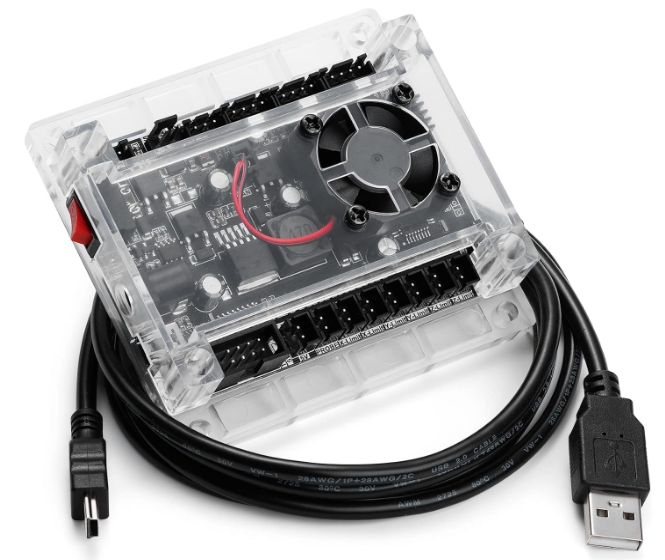
The SainSmart Genmitsu Controller Board 1810 Pro is a high-performance control board designed for CNC machines. It is built with advanced technology to ensure efficient and precise control over your CNC router, milling machine, or engraving machine. The estimated price of this product is around $120, and it is now available for purchase.
Parts List
GRBL Controller
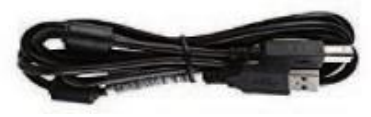
USB cable (USB-A <-> mini-USB)
Optional Accessories
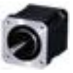
- 5.5W Engraving CNC milling cutter
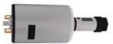
- Laser module material
Milling chuck
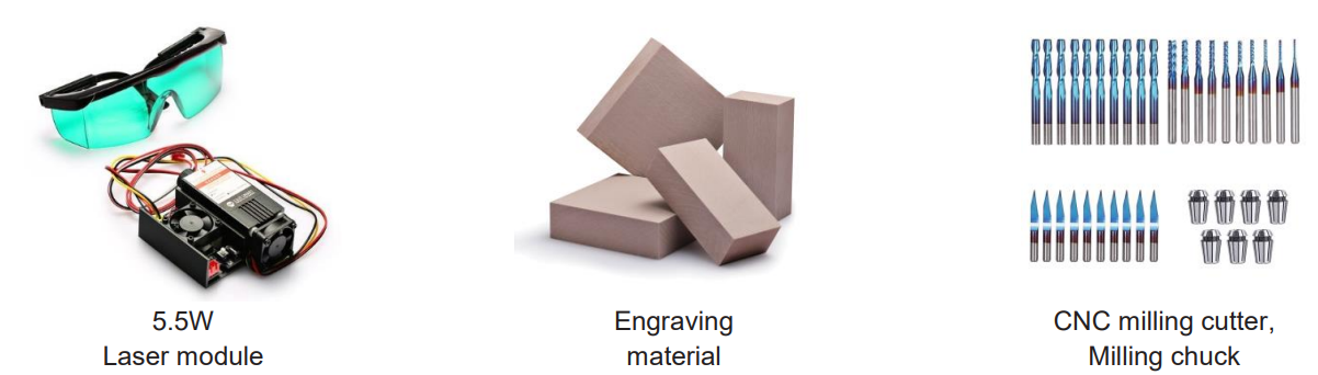
Accessories for your milling/engraving machine are best purchased from SainSmart.
Detailed Specifications
The Genmitsu Controller Board 1810 Pro features a powerful 32-bit Cortex-M3 processor, which ensures fast and accurate processing. It has a built-in driver that supports up to four stepper motors, making it ideal for multi-axis CNC machines. The board has a maximum current rating of 2.8A per phase, which is sufficient for most CNC applications. It also features a built-in USB port for easy connectivity to your computer. The board's dimensions are 110mm x 75mm x 20mm, making it compact and easy to install.
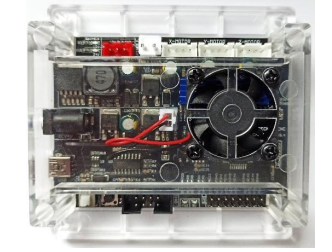
Control Module Design
- The control module measures just 91mm x 87mm x 23mm.
- It has a very quiet, brushless fan which provides sufficient cooling for the three A4988 stepper motor drivers, which have a common aluminium heat sink.
Each of these 3 stepper motor drivers can deliver a motor current of up to 2A at 12V. For the NEMA42 or NEMA57 stepper motors typically used in CNC milling/engraving machines, these stepper motor drivers offer more than enough power and do not need to be operated at the upper end of their specification.
Hint: During the first turn on, please set the current required for the stepper motors using the three miniature potentiometers located on the board. This is described in more detail in a later chapter under the heading "Setting Vref".
Description
The SainSmart Genmitsu Controller Board 1810 Pro is designed to provide efficient and precise control over your CNC machine. It features a user-friendly interface that makes it easy to configure and operate. The board supports GRBL firmware, which is widely used in the CNC community. It also features a real-time clock that ensures accurate timings and movements. The board's sturdy construction and high-quality components ensure reliable and long-lasting performance. It is compatible with most CNC software, making it a versatile solution for your CNC needs.
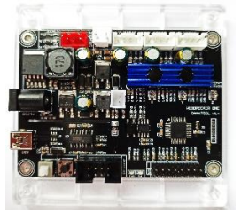
Connection and Operating Elements
The following elements are located on the upper side of the control module, seen from left to right:
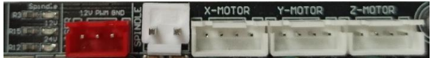
- Light emitting diodes for Spindle/Laser (blue), +12V (red), +24V (red)
- Connection for PWM-controlled 12V DC laser module (red)
- Connection for 24VDC spindle motor (white)
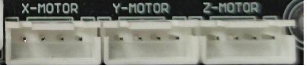
- Connection for stepper motor of X-axis (white)
- Connection for stepper motor of the Y-axis (white)
- Connection for stepper motor of Z-axis (white)
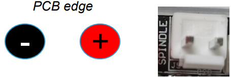
Connection for 24V Spindle Motor
The connection for the 24VDC spindle motor is controlled by an IRF024 N-channel MOSFET with a maximum load of 10A. Since the MOSFET is not cooled, the maximum load capacity should not be used. However, this is still quite sufficient to operate a 775ER type motor. The speed of the spindle motor is controlled by pulse width modulation (PWM).
Pin assignment:
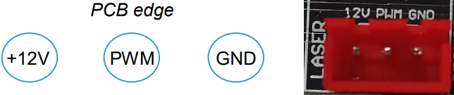
Connection for 12V PWM Laser Module
A PWM-controlled laser module can be connected to the red, 3-pin connector. Please note that either the spindle motor or a laser module is connected to their respective connectors. Simultaneous connection and operation of spindle motor and laser module is not supported by the control module.
Pin assignment:
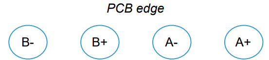
Connection for Stepper Motors
The module comes with 4-pin connectors for 3 stepper motors. One for the X-, one for the Y- and another one for the Z-axis.
Pin assignment:
XH 2.54 type
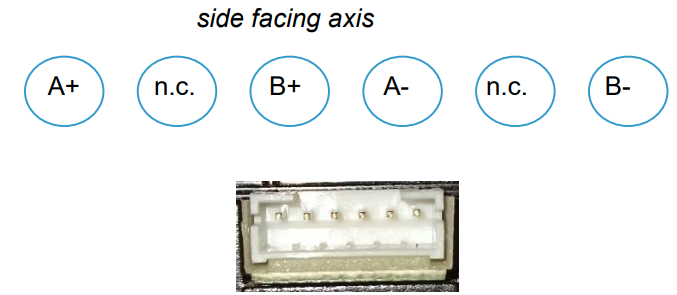
Those stepper motors, that come with a built-in 6-pin PH 2.00 type header, normally have their pins assigned as follows.
Pin assignment:
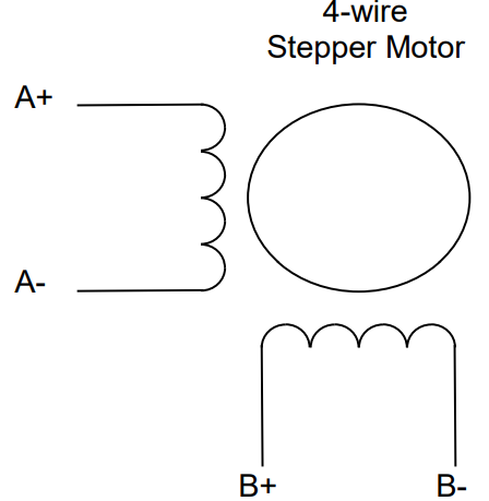
PH 2.00 type
Connection for External 24V Power Supply Unit
On the left side of the control board, there is a DC power jack for connecting an external 24VDC power supply. The outer ring is connected to GND whilst the inner pin is connected to +24V.
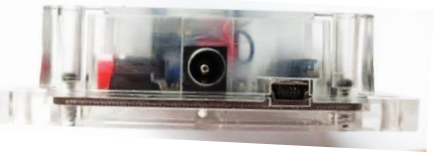
Connection for PC
A PC can be connected via the mini-USB socket, which is also located on the left side of the control module. The USB port is connected to the central processor of type Atmel ATMEGA328P via a USB-to-serial converter of type CH340. The ATMEGA328P comes with a bootloader and the GRBL firmware version 1.1f already preinstalled at the factory.
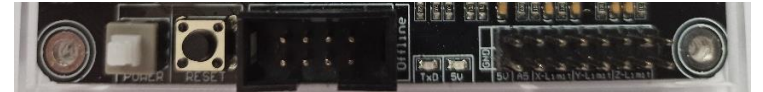
On the bottom side of the control module, the following elements are located, as seen from left to right:
- On/Off switch
- Reset button
- 8-pin connector for offline-controller
- Light emitting diode for TxD (blue)
- Light emitting diode for +5V (red)
16-pin connector for Z-Probe (measuring tool) as well as Z-, Y- and X-limit switches
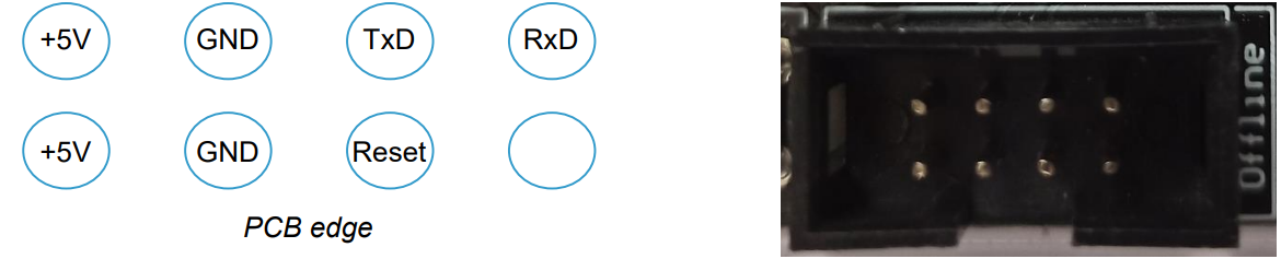
Connection for Offline-Controller
An external offline-controller can be connected to the 8-pin tub connector. This makes it possible to operate the CNC milling/engraving machine connected to the control module independently without an additional PC. In such a case, the positioning data (g-code) are stored beforehand on a micro-SD card located in the offline-controller.
Pin assignment:
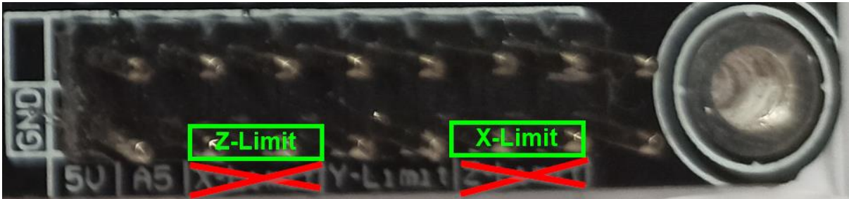
Connection for Limit Switches and Z-Probe
Limit switches as well as a measuring device for the Z-axis (Z-probe) can be connected via the 16-pin plug that is also available at the bottom edge of the control module.
Pin assignment:
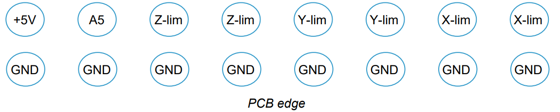
Hint: Please note that the labeling for the connections of the X- and Z-limit switches on the board is reversed.
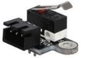
Connection of Limit Switches
For each of the 3 axes, there are connections for two limit switches on the control module. The connections of the limit switches of one axis are connected in parallel to each other. The direction of movement enables the control module to differentiate which limit switch was triggered.
Activate Homing Using Limit Switches: In order for the control board to evaluate the limit switches in the context of a homing run, this must first be switched on in the control module. Homing is controlled by Grbl parameter $22. If limit switches are used, enter "$22=1" in the Grbl or LaserGrbl command line to activate them and "$22=0" to deactivate them. A homing run can then be triggered by entering "$H".
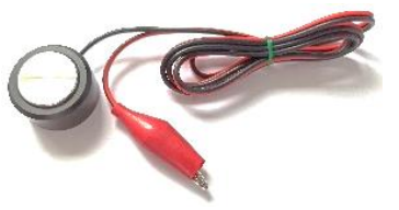
Connecting a Z-Probe (Measuring Tool): To automatically determine the distance between the tip of the milling cutter and the surface of the workpiece to be milled, an additional measuring tool, a so-called Z-probe, can be used. This is connected to terminal A5 of the 16-pin connector and the opposite GND terminal.
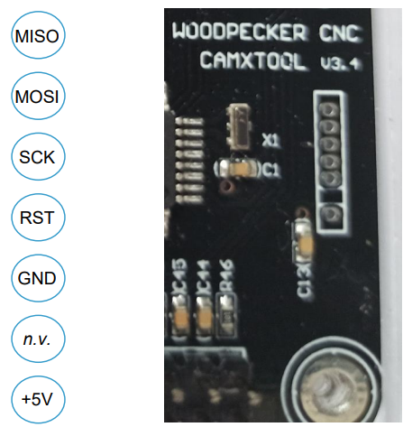
ICSP Interface
On the right side of the board, there are 6 pads for the ICSP interface (in-circuit serial programming). They have been set up in a 1.27mm grid. Since a bootloader is already preinstalled on the ATMEGA328P at the factory, this interface is normally no longer required for later operation of the control board. Therefore, no pin header has been installed.
Setting Vref
Before connecting stepper motors to the control module, the maximum motor currents for the stepper motors used must first be set on the control module using the appropriate miniature potentiometers. For the stepper motor drivers of the type A4988 used in the control module, the formula for determining the maximum motor current is:
Imax (maximum motor current) = Vref / (8 x Rsense)
Rsense has a resistance value of 0.1Ω for this control module. Converted to Vref it makes the following formula:
Vref = Imax (maximum motor current) x 0.8Ω
Thus, for an ordinary stepper motor with a maximum motor current of 0.8A, this results in a Vref value of 0.8A x 0.8Ω = 640mV.
To set the reference voltage Vref, you need a multimeter and an adjustment screwdriver. Connect the COM port of your multimeter to GND. GND is, for example, on all pins of the 16-pin male connector pointing to the lower edge of the board. Hold the V connector tip of your multimeter to the middle connector of the corresponding miniature potentiometer (X, Y, or Z). Then set the required voltage value Vref on the miniature potentiometer with the adjustment screwdriver.
Assembly and Operation
Assembly
Please refer to the manual of your milling/engraving machine for assembly instructions. Pay attention to the required cable lengths of the supply lines to all movable elements. If possible, use additional fabric hoses to protect the supply lines. Mounting material is not included in the package of the control module.
Power Supply
The control module requires a 24VDC supply for operation. The required current depends on the connected CNC milling/engraving machine. Usually, a DC power supply with 24V rated at 5A is sufficient.
Operation
Connect up to three stepper motors to the terminals labeled "X-MOTOR", "Y-MOTOR", and "Z-MOTOR".
A spindle motor is connected to the 2-pole "SPINDLE" connection. Pay attention to the polarity. The plus pole is usually marked red whilst the minus pole is marked black.
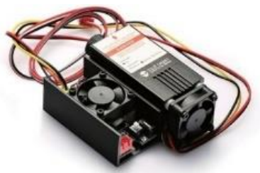
A PWM laser module, such as the blue SainSmart 5500MW laser module, can be connected to the red 3-pin connector labeled "LASER" using the 3-core cable supplied with the laser module. Note that either a spindle motor is connected to the "SPINDLE" connector or a laser module is connected to the "LASER" connector, but never both at the same time.
- In addition, limit switches for the X-, Y-, and Z-axes can be connected to the 16-pin connector.
- In order to put the device into operation, either an offline controller can be connected to the 8-pin post socket or a PC can be connected to the USB port of the control module.
- When operating with an offline controller, it is possible to manually move the 3 axes (jogging) after turning on the device. The on/off switch is located at the lower left edge of the control module.
- Additional software is required for operation with a PC. For CNC milling/engraving work, we recommend Grbl, and for laser work, LaserGRBL. Both programs are OpenSource.
- We wish you much pleasure and success when operating a device connected to this control module.
Setup Guide
To set up the Genmitsu Controller Board 1810 Pro, follow these steps:
- Install the GRBL firmware on the board using the Arduino IDE.
- Connect the board to your CNC machine's stepper motors and other components.
- Connect the board to your computer using the USB cable.
- Configure the board's settings using a CNC software such as Universal Gcode Sender or Candle.
- Test the board by running a simple Gcode program.
Genmitsu Controller Update Firmware
Grbl v1.1f comes preinstalled on the control module. Should it become necessary to replace the delivered firmware with a newer one, this is also possible at any time thanks to the built-in bootloader.
CH340 Device Driver
For Windows 7 users, the CH340 driver must be installed first in order to communicate with the control board. For Windows 10 users, this driver is automatically installed the first time the control board gets connected to the computer via a USB connection.
Download Update-Archive
Now download the appropriate firmware for your CNC milling/engraving machine, preferably directly from the manufacturer's website. Usually, this is an archive file. It contains both the required firmware file of type ".hex" and the "xloader" program required for transfer. If the xloader is not included in your update archive, you can also find it on the Internet by searching for "xloader arduino".
Hint: SainSmart is not liable for damage to the control module or other modules and devices connected to it resulting from improper or incorrect firmware installation. SainSmart is also not liable for any other damage to persons or property.
Installing the Firmware
- Connect the control module to a Windows PC with a USB connection. The USB port of the PC supplies the microprocessor of the control module with sufficient voltage. Therefore, make sure that the CNC controller's external power supply is disconnected or switched off.
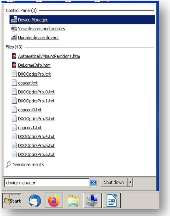
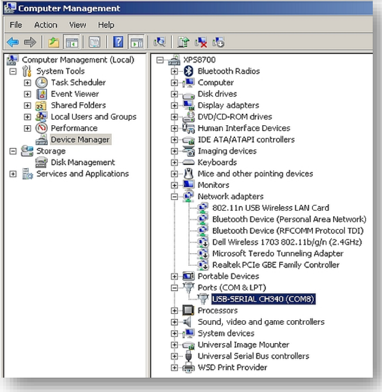
Find the Device Manager application by typing "Device Manager" in the Windows 7 "Start" window. For Windows 10, type "Device Manager" in the search window. Start the Device Manager application by left-clicking it.
In Device Manager, locate the "Ports (COM & LPT)" entry and click it to display the active driver that is in use. For this CNC control board, it should be "CH340", but it may display different COM port numbers. Make a note of the COM port number as it will be needed later.
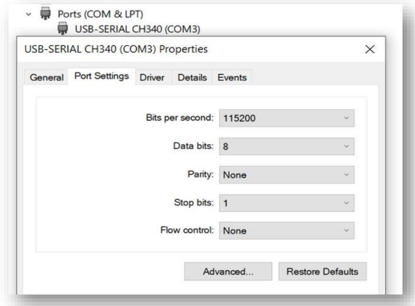
Double-click the highlighted driver line to expand it. When expanded, it will display multiple tabs, click the Port Settings tab and set it to transfer at 115200 bits per second.
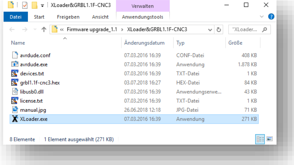
Use the file manager to navigate to the directory where you saved the update file and unpack it. In the created file there is usually also an executable program called "XLoader". Double-click on this program to start it and ignore any error messages that may appear.
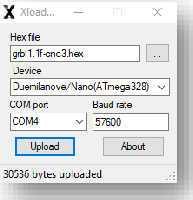
In the Hex file window, click the name of the hex file required to update the GRBL version of your control board. In the "Device" window, select "Duemilanove/Nano(ATmega328)" as the device type. In the "COM Port" window, enter the same COM port number that you noted down in step 3. Set the baud rate to "115200". Only then click on the "Upload" button. As soon as the specified hex file has been completely uploaded to the control module, a message is displayed which also shows the number of bytes uploaded. The value depends on the size of the hex file.
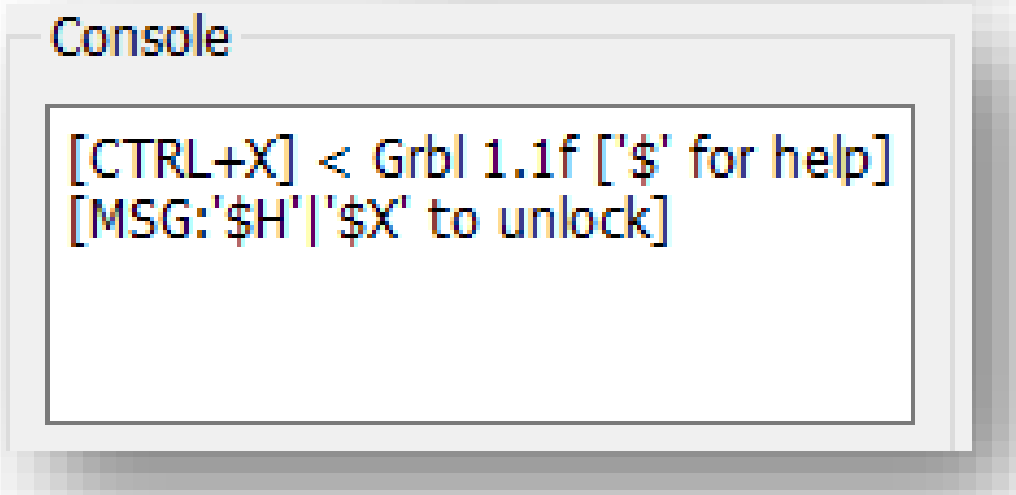
Start Grbl (Candle) on your PC and in the status window check whether a version number is displayed. This final check completes the upgrade process of the control module.
Troubleshooting
If you encounter any issues with the Genmitsu Controller Board 1810 Pro, try the following troubleshooting steps:
- Check the board's connections and ensure that all components are securely connected.
- Make sure that the GRBL firmware is properly installed and configured.
- Check the CNC software settings and ensure that they match the board's configuration.
- If the board is not responding, try resetting it by disconnecting and reconnecting the power supply.
- If the issue persists, contact SainSmart's customer support for further assistance.
Pros & Cons
Pros
- Powerful 32-bit processor for fast and accurate processing.
- Built-in driver that supports up to four stepper motors.
- Compatible with most CNC software and GRBL firmware.
- User-friendly interface and easy to configure.
- Sturdy construction and high-quality components for reliable performance.
Cons
- May be expensive for some users.
- Requires some technical knowledge to set up and configure.
Customer Reviews
Customers have praised the Genmitsu Controller Board 1810 Pro for its fast and accurate processing, easy configuration, and reliable performance. Some have noted that the board can be a bit difficult to set up for beginners, but once set up, it works flawlessly. Overall, customers are satisfied with their purchase and recommend the board for CNC enthusiasts and professionals alike.
Most Common Complaints
The most common complaint about the Genmitsu Controller Board 1810 Pro is its high price point. Some users have also noted that the board can be difficult to set up and configure, especially for beginners. However, once set up, most users agree that the board's performance and reliability make it worth the effort.
Faqs
What is the SainSmart Controller Board 1810 Pro for Genmitsu?
Which kind of CNC machines can be used with the Genmitsu Controller Board 1810 Pro?
What are the Genmitsu Controller Board 1810 Pro's primary features?
For what software does the Genmitsu Controller Board 1810 Pro work with?
How can I link my PC to the Genmitsu Controller Board 1810 Pro?
What power source does the Genmitsu Controller Board 1810 Pro require?
Are laser modules compatible with the Genmitsu Controller Board 1810 Pro?
Is it possible to update the Genmitsu Controller Board 1810 Pro's firmware?
The Genmitsu Controller Board 1810 Pro can control how many axes?
For what kind of stepper motors does the Genmitsu Controller Board 1810 Pro work with?
Leave a Comment