Trion TESKIT09CH Kito Electric Shower Instruction Manual
Content
Introducing the Trion TESKIT09CH Kito Electric Shower
This book contains all the necessary fitting and operating instructions for your Triton electric shower. Please read them carefully. The shower installation must be carried out by a suitably qualified person and in the sequence of this instruction book. Care taken during the installation will provide a long, trouble-free life from your shower.
Detailed Specifications
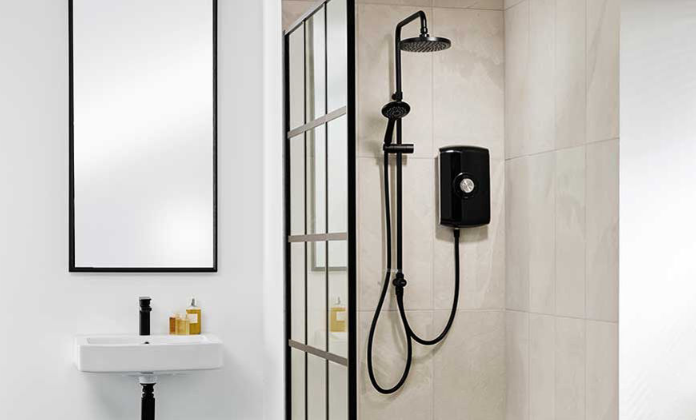
The Trion TESKIT09CH Kito Electric Shower is a powerful and stylish shower unit that boasts several impressive features. These include a 9.5 kW thermostatic heating element, Phased Shutdown technology, rub-clean showerhead, and an easy-to-use dial control. The unit is also made of high-quality chrome and features a sleek and modern design.
Specifications
Electrical
- Nominal power rating at 240V:
- 9.5kW – (40A MCB rating)
- 10.5kW – (45A MCB rating)
- Nominal power rating at 230V:
- 8.7kW – (40A MCB rating)
- 9.6kW – (40A MCB rating)
Water
- Inlet connection: 15 mm diameter.
- Outlet connection: ½” BSP male thread.
Entry Points
- Water: bottom, back, or right-hand side entry.
- Cable: top or back.
Materials
- Backplate, cover, controls, showerhead: ABS.
- Sprayplate: Acetal.
- Elements: Minerally insulated corrosion resistant metal sheathing.
Dimensions
- Height: 308mm
- Width: 211mm
- Depth: 95mm
Standards and Approvals
- Splashproof rating: IPX4.
- Complies with the requirements of current British and European safety standards for household and similar electrical appliances.
- Complies with requirements of the British Electrotechnical Approvals Board (BEAB).
- Meets with Compliance with European Community Directives (CE).
Advice to Users
When first installed, the unit will be empty. It is essential the unit should contain water before the elements are switched on. It is vital that the commissioning procedure is followed. Failure to carry out this operation will result in damage to the unit and will invalidate the guarantee.
The following points will help you understand how the shower operates: a. The electric heating elements operate at a constant rate at your chosen power setting. The rate of the water passing through the heater determines the water temperature. (The slower the flow, the hotter the water becomes; the faster the flow, the cooler the water). b. During winter, the mains water supply will be cooler than in the summer, so the flow rate will vary between seasons at any one temperature setting. At different times of the year, you may have to adjust the position of the temperature control to maintain your desired temperature setting. c. The stabiliser valve minimizes variations in shower temperature during mains water pressure changes. If changes in shower temperature are experienced during normal use, it will most likely be caused by the water pressure falling near to or below the minimum level. The drop in pressure may be due to water being drawn off at other points in the house whilst the shower is in use. If pressure drops appreciably below the minimum, the heating elements will automatically cut out.
If ever the water becomes too hot and you cannot obtain cooler water, first check that the sprayplate in the showerhead has not become blocked. Do not place items such as soap or shampoo bottles on top of the unit. Liquid could seep through the joint between the cover and backplate and possibly damage the sealing rubber.
Main Components
Inside unit (fig.1)
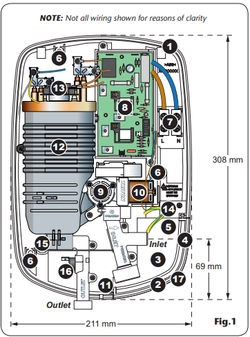
- Top cable entry
- Bottom pipe entry
- Rear pipe entry area
- Side pipe entry area
- Rear cable entry area
- Wall screw fixing
- Terminal block
- Power PCB
- Stabilising valve
- Solenoid valve
- Guide pockets
- Can and element assembly
- Thermal cut-out (main)
- Earth connection
- Pressure relief device
- Outlet temperature regulator
Trimplate
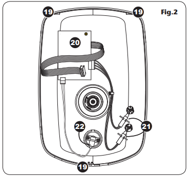
Inside cover (fig.2)
- Cover tags
- Control PCB
- Neon & bracket
- Start/Stop switch
Electrical Requirements
WARNING! THIS APPLIANCE MUST BE EARTHED
The installation, supply cable, and circuit protection must conform with BS 7671 (IEE wiring regulations) and be sufficient for the amperage required. The following notes are for guidance only:
- The shower must only be connected to a 230-240V AC supply. If you are installing a shower with a kilowatt rating above 9kW, it is advisable to contact the local electricity supply company.
The electrical rating of the shower is shown on the rating label (Fig.3) within the unit.
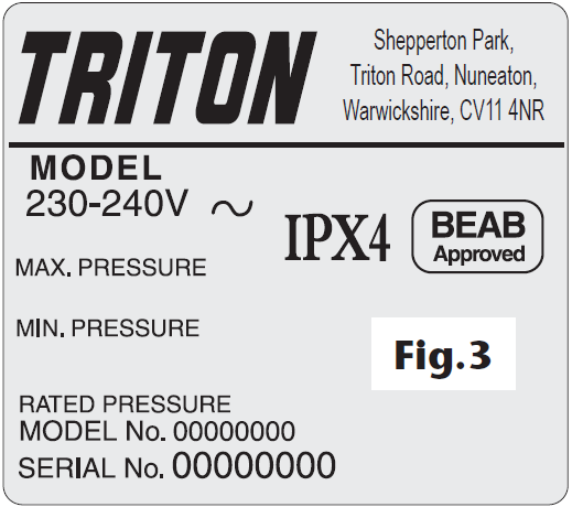
- Before making any sort of electrical connection within the installation, make sure that no terminal is live. If in any doubt, switch off the whole installation at the mains supply and remove the correct fuse.
- The shower must be connected to its own independent electrical circuit. IT MUST NOT be connected to a ring main, spur, socket outlet, lighting circuit, or cooker circuit.
- The electrical supply must be adequate for the loading of the unit and existing circuits.
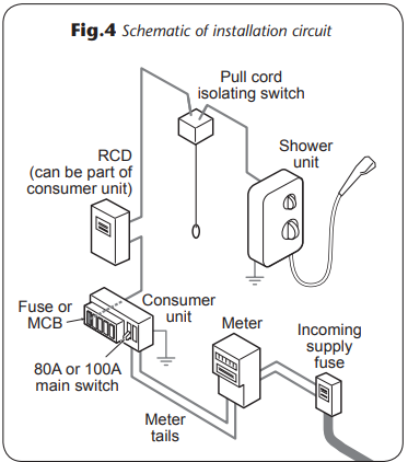
Check your consumer unit (main fuse box) has a main switch rating of 80A or above and that it has a spare fuse way which will take the fuse or Miniature Circuit Breaker (MCB) necessary for the shower (Fig.4).
- If your consumer unit has a rating below 80A or if there is no spare fuse way, then the installation will not be straightforward and may require a new consumer unit serving the house or just the shower.
- You will need to contact the local electricity company. They will check the supply and carry out what is necessary.
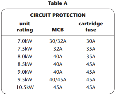
For close circuit protection, DO NOT use a rewireable fuse. Instead, use a suitably rated Miniature Circuit Breaker (MCB) or cartridge fuse (see Table A).
- A 30mA residual current device (RCD) must be installed in all UK electric and pumped shower circuits. This may be part of the consumer unit or a separate unit.
- A 45 amp double pole isolating switch with a minimum contact gap of 3 mm in both poles must be incorporated in the circuit.
- It must have a mechanical indicator showing when the switch is in the OFF position, and the wiring must be connected to the switch without the use of a plug or socket outlet.
- The switch must be accessible and clearly identifiable but out of reach of a person using a fixed bath or shower, except for the cord of a cord-operated switch, and should be placed so that it is not possible to touch the switch body while standing in a bath or shower cubicle. It should be readily accessible to switch off after using the shower.
- Where shower cubicles are located in any rooms other than bathrooms, all socket outlets in those rooms must be protected by a 30mA RCD.
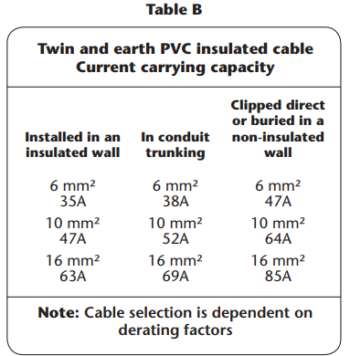
The current carrying capacity of the cable must be at least that of the shower circuit protection (see Table B).
- To obtain full advantage of the power provided by the shower, use the shortest cable route possible from the consumer unit to the shower.
- It is also necessary to satisfy the disconnection time and thermal constraints which means that for any given combination of current demand, voltage drop, and cable size, there is a maximum permissible circuit length.
- The shower circuit should be separated from other circuits by at least twice the diameter of the cable or conduit.
- The current rating will be reduced if the cabling is bunched with others, surrounded by thermal loft or wall insulation, or placed in areas where the ambient temperature is above 30°C. Under these conditions, derating factors apply and it is necessary to select a larger cable size.
- In the majority of installations, the cable will unavoidably be placed in one or more of the above conditions. This being so, it is strongly recommended to use a minimum of 10mm cabling throughout the shower installation.
- In any event, it is essential that individual site conditions are assessed by a competent electrician in order to determine the correct cable size and permissible circuit length.
Water Requirements
The installation must be in accordance with Water Regulations/Bylaws. To ensure activation of the heating elements, the shower must be connected to a mains water supply with a minimum running pressure of 100kPa (1.0 bar) at a minimum flow rate of nine litres per minute for the 9.5kW rated model. For the 10.5kW rated shower, the minimum running pressure must be 150kPa (1.5 bar) at a minimum flow rate of eleven litres per minute. For all units, the maximum static pressure must be no greater than 1000kPa (10 bar). If in any doubt, the pressure should be checked.
Note: If the stated flow rate is not available, it may not be possible to achieve optimum performance from the unit throughout the year. During periods of high ambient temperatures, it may be necessary to select a low power setting to achieve your preferred shower temperature. The water supply can be taken from a cold water storage cistern provided there is a minimum head of ten metres (fifteen metres for the 10.5kW model). Minimum head is the vertical distance from the base of the cistern to the showerhead. It must be an independent supply to the shower only. If it is intended to operate the shower at pressures above the maximum or below the minimum stated, contact Triton Customer Service for advice.
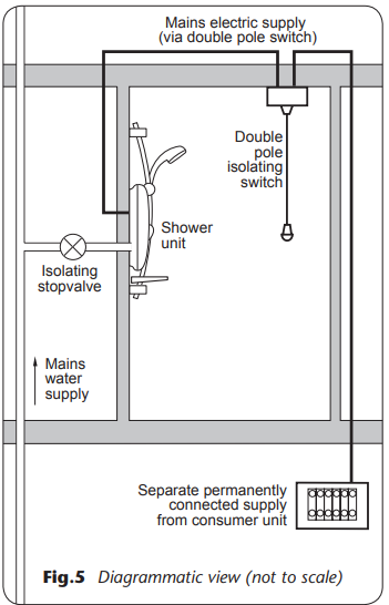
Fig 5. shows a typical system layout. Do not use jointing compounds on any pipe fittings for the installation.
Siting of the Shower
IMPORTANT: If installing onto a tiled wall, always mount the unit on the surface of the tiles. NEVER tile up to the unit.
Refer to fig.6 for the correct siting of the shower. Position the unit where it will not be in direct contact with water from the showerhead. Position the shower unit vertically. Allow enough room between the ceiling and the shower to access the cover top screws. Leave enough space between the left-hand side of the unit and the wall to allow access to the pressure relief device (PRD) in the future.
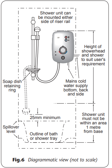
Note: Water regulations require the showerhead to be ‘constrained by a fixed or sliding attachment so that it can only discharge water at a point not less than 25mm above the spill-over level of the relevant bath, shower tray, or other fixed appliance’. The use of the supplied gel hanger/hose guide will in most cases meet this requirement, but if the showerhead can be placed within a bath, basin, or shower tray, then a double check valve, or similar, must be fitted in the supply pipework to prevent back-flow.
Pressure Relief Safety Device
A pressure relief device (PRD) is designed into the shower unit which complies with European standards. The PRD provides a level of appliance protection should an excessive build-up of pressure occur within the shower. Do not operate the shower with a damaged or kinked shower hose, or a blocked showerhead which can cause the PRD to operate. When commissioning, the showerhead must be removed from the flexible hose, while at the same time the temperature control must be at the minimum flow position. Failure to follow this procedure may also cause the PRD to operate.
Make sure the shower is positioned over a bath or shower tray because if the PRD operates, then water will eject from the bottom of the unit. Should this happen, turn off the electricity and water supplies to the shower at the isolating switch and stop valve. Contact Customer Service for advice on replacing the PRD.
WARNING! The shower must not be positioned where it will be subjected to freezing conditions.
IMPORTANT: The unit must be mounted on a flat surface which covers the full width and length of the backplate. It is important that the wall surface is flat; otherwise, difficulty may be encountered when fitting the cover and subsequent operation of the unit may be impaired.
Fitting the Shower to the Wall
WARNING! Check there are no hidden cables or pipes before drilling holes for wall plugs. Use great care when using power tools near water. The use of a residual current device (RCD) is recommended.
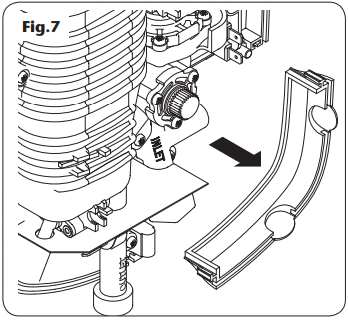
Note: The control knob is an integral part of the cover – do not attempt to remove it. Lift the cover from the backplate. To access the pipe and cable connections lift off the trim plate (fig.7). Entry positions for the mains water are from the bottom, rear, or side. Cable entry is via the top or rear.
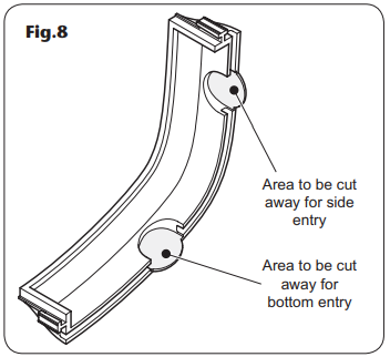
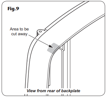
Note: Deviations from the designated entry points will invalidate product approvals. If bottom or side surface entry is required for the mains cold water, then the necessary opening will need to be cut out in the trim plate (fig.8). If surface cable entry from the top is required then a small area will need to be cut out in the backplate (fig.9). If installing a feed pipe from the rear, bottom, or side, the center of the inlet valve to the wall surface is 21mm (fig.10).
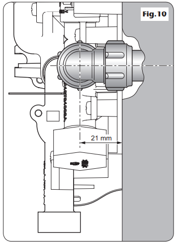
Note: If entry is from the rear, the nut of the compression fitting will be partially behind the surface of the wall (fig.10). This area must be left clear when plastering over the pipework in order to make the nut accessible for future adjustments.
IMPORTANT
- Always seal around the incoming pipework to prevent water from entering the wall.
After choosing the site for the shower, use the backplate as a template and mark the three fixing holes (fig.11). Drill and plug the wall. (An appropriate drill bit should be used.
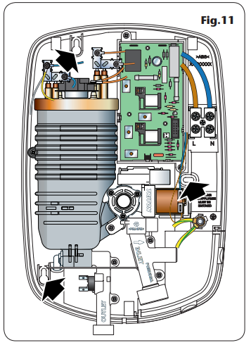
- If the wall is brick, plasterboard, or a soft building block, appropriate wall plugs and screws should be fitted).
- Screw the top and bottom fixing screws into position leaving the base of the screw heads protruding 6mm out from the wall.
- Hook the backplate over the top and bottom screws and fit the center fixing screw into position.
- Do not fully tighten the screws at this stage, as the fixing holes are elongated to allow for out-of-square adjustment after the plumbing connections have been completed.
WARNING! The outlet of the shower acts as a vent and MUST NOT be connected to anything other than the hose and showerhead supplied.
Plumbing Connections
Plumbing to be carried out before wiring
Do not use jointing compounds on any pipe fittings for the installation. Do not solder fittings near the shower unit as heat can transfer along the pipework and damage components. Compression fittings must be used to connect to the inlet of the shower. (Push-on fittings must not be used as full engagement cannot be guaranteed).
Note: An additional stop valve (complying with Water Regulations) must be fitted in the mains water supply to the shower as an independent means of isolating the water supply should maintenance or servicing be necessary.
IMPORTANT: Before completing the connection of the water supply to the inlet of the shower, flush out the pipework to remove all swarf and system debris. This can be achieved by connecting a hose to the pipework and turning on the mains water supply long enough to clear the debris to waste.
Procedure
- Turn off the water supply either at the mains stop valve or the isolating stop valve.
- Connect the mains water supply to the inlet of the shower via 15mm copper, stainless steel, or plastic pipe using a 15mm x 15mm brass elbow or straight coupler compression fitting.
- Do not use excessive force when making these connections.
- Make sure the backplate is square on the wall and tighten the two retaining screws which hold it to the wall.
- Turn on the mains water supply and check for leaks in the pipework connection to the shower.
- Note: At this stage no water can flow through the unit.
Electrical Connections
Switch off the electricity supply at the mains.
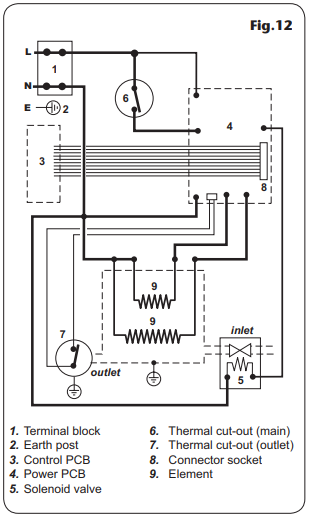
Fig.12 shows a schematic wiring diagram. The cable entry points are shown in fig.1. The cable can be surface clipped, hidden, or via 20mm conduit.
Note: Conduit entry can only be from the rear. Route the cable into the shower unit and connect to the terminal block (fig.13) as follows:
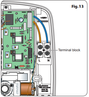
- Earth cable to terminal marked
- Neutral cable to terminal marked N
- Live cable to terminal marked L
IMPORTANT: Fully tighten the terminal block screws and make sure that no cable insulation is trapped under the screws. Loose connections can result in cable overheating.
Note: The supply cable earth conductor must be sleeved. The outer sheath of the supply cable must be stripped back to the minimum. The supply cable must be secured either by routing through conduit or in trunking or by embedding in the wall, in accordance with current IEE regulations. The use of connections within the unit to supply power to other equipment i.e. extractor fans, pumps, etc. will invalidate the guarantee. DO NOT switch on the electricity supply until the cover has been fitted.
Note: The elements on UK models are to 240V specification and will give a lower kW rating if the voltage supply is below 240V.
Commissioning
WARNING! Before normal operation of the shower, it is essential the following commissioning procedure is completed correctly. At this stage, temporarily fit the cover in order to carry out the commissioning procedure. The first operation of the shower is intended to flush out any remaining unit debris and to make sure the heater unit contains water before the elements are switched on.
- Refit the trim plate.
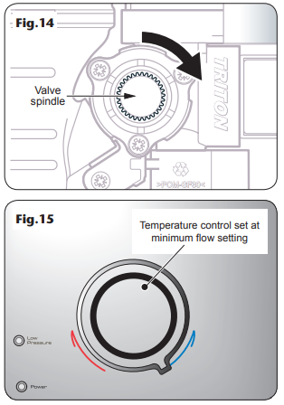
- Turn the valve spindle fully clockwise until the spindle hits the ‘stop’ (fig.14). Do not force the spindle.
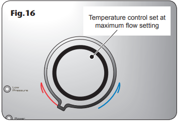
Turn the temperature control on the cover to the minimum flow position (fig.15).
- Offer the cover to the unit.
- IMPORTANT! Do not connect the 10-way ribbon cable at this stage.
- Carefully locate the cover onto the backplate and make sure the wires are not trapped.
- Guide the cover into position so that the control spindle locates correctly (minor adjustment may be necessary to align the control and spindle). Should any difficulty arise, recheck the points above.
- While applying slight pressure to the front cover, secure in position with the three retaining screws.
- Fit the flexible hose to the shower outlet making sure the outlet of the hose is directed to waste. Check the supplied sealing washer is in place. Do not attach the showerhead at this stage.
- Before turning on the electric and mains water supplies to the shower, make sure the temperature control is rotated fully clockwise to ‘HOT’, the minimum flow position (fig.15).
- Note: Failure to rotate the valve spindle fully clockwise may cause the PRD to operate.
- Turn on the water supply to the shower at the isolating stop valve. Switch on the electricity supply to the shower at the isolating switch.
- Wait until water starts to flow from the flexible hose.
Slowly rotate the temperature control fully anti-clockwise, the maximum flow position (fig.16).
- It will take about thirty seconds for a smooth flow of water to be obtained while air and any debris are being flushed from the shower. When a smooth flow of water is obtained, turn the temperature control from minimum flow to maximum flow and back again several times to release any trapped air from within the unit.
- Once the flushing out has been completed, switch off the electricity to the shower at the isolating switch. The water will cease to flow.
- Unscrew the top and bottom cover retaining screws and lift the cover from the backplate.
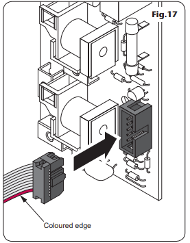
Attached to the control and display PCB, inside the cover, is a 10-way ribbon cable. The ribbon cable connector must be plugged into the socket located at the right of the power PCB situated inside the unit (fig.17). Note the cable connector can be fitted to the socket only one way. The ribbon cable has a colored edge which is lowermost when correctly fitted to the socket.
- Note: Make sure the cable is not trapped when fitting the cover.
Replacing the Cover
Important: Before finally fitting the cover, the following steps must be taken:
- Check the plumbing connections are watertight.
- Check the terminal block screws are fully tightened.
- Make sure the pipe and cable entering the unit do not prevent the cover from locating correctly to the backplate.
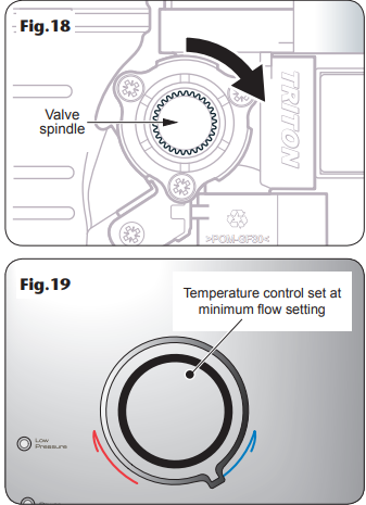
- Rotate the valve spindle fully clockwise until the spindle hits the 'stop' (fig.18). Do not force the spindle.
Turn the temperature control on the cover fully clockwise to the minimum flow position (fig.19).
- Offer the cover to the unit.
- Carefully locate the cover tags into the guide pockets on the backplate and make sure the wires are not trapped.
- Guide the cover into position so that the knob spindle locates correctly (minor adjustment may be necessary to align the knob and spindle). Should any difficulty arise, recheck the points above.
- While applying slight pressure to the front cover, secure in place using the three retaining screws.
WARNING! Before normal operation of the shower, it is essential the following commissioning procedure is completed correctly.
When the electricity supply to the shower is switched on at the isolating switch, the power indicator will light.
To Start the Shower
Press the Start/Stop button and water will begin to flow. Note: The default start-up setting is the HIGH setting.
To Stop the Shower
Press the Start/Stop button and the phased shutdown will begin. Water will cease to flow after a few seconds.
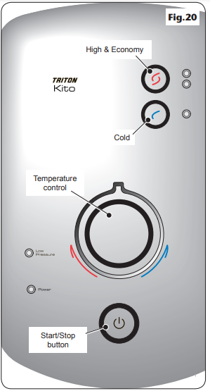
To Use the Control Buttons
There are two control buttons – high/economy and cold (fig.20). The upper button is for switching between the high and economy power settings. The high setting allows the highest flow achievable for your preferred temperature. This setting should normally be regarded as optimum shower performance throughout the year. The economy setting uses less energy when the ambient mains water temperature is high during hot months.
Note: When starting the shower, the default setting is high. The upper button alternates between the two settings. Press the button once to select the Economy setting; press the button again to reselect High. Temperature adjustment at this setting is via the temperature control. The lower button is for COLD water only. Adjusting the temperature control at this setting will only increase or decrease the flow of the water from the showerhead. (It will not alter the water temperature.)
Note: In normal use, it is in order to leave the water supply permanently on to the shower unit, but as with most electrical appliances, the unit must be switched off at the isolating switch when not in use.
Description
The Trion TESKIT09CH Kito Electric Shower is the perfect addition to any modern bathroom. With its powerful 9.5 kW thermostatic heating element, you can enjoy a refreshing and invigorating shower every time. The Phased Shutdown technology ensures the element is safely cooled before shutting off, prolonging the life of the unit. The rub-clean showerhead makes cleaning a breeze, while the dial control allows for easy temperature and flow adjustments. Plus, the high-quality chrome finish adds a touch of sophistication and style to any bathroom.
Operating
WARNING! After any servicing of the mains water supply, always flush out the pipework to remove any debris. Always make sure the unit is started on COLD in order to purge any air in the pipework.
Note: If the stated flow rate required for the unit cannot be met due to low water pressure, it will be necessary to operate the unit on the ECONOMY setting during the warmer months because of flow rate limitations entering the unit.
To Adjust the Shower Temperature
The water temperature is altered by increasing or decreasing the flow rate of the water through the shower via the temperature control (fig.21). After finding a suitable showering temperature, the temperature control can be left as the normal setting and should only need altering to compensate for seasonal changes in ambient water temperature.
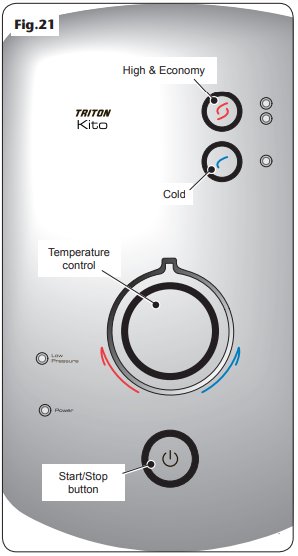
Note: The preferred position on economy will give a different temperature to the same position on high.
To Decrease the Shower Temperature
Turn the temperature control anti-clockwise; this will increase the flow of water through the shower.
To Increase the Shower Temperature
Turn the temperature control clockwise; this will decrease the flow of water through the shower.
Note: It is advisable to be certain that the showering temperature is satisfactory by testing with your hand before stepping under the showerhead. There will always be a time delay of a few seconds between selecting a flow rate and the water reaching the stable temperature for that flow rate.
Caution: This appliance is not intended for use by persons (including children) with reduced physical, sensory, or mental capabilities, or lack of experience and knowledge, unless they have been given supervision or instruction concerning use of the appliance by a person responsible for their safety. Children should be supervised to ensure that they do not play with the appliance.
Operating Functions
Power On Indicator
When the electricity supply to the shower is switched on at the isolating (fig.22) switch, the power indicator will light.
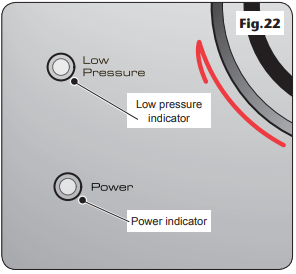
Low Pressure Indicator
If this indicator lights, this means the water pressure has fallen below the minimum required for the correct operation of the shower, resulting in the low pressure cut-out operating. This switches off power to the heating elements preventing any undue temperature rises. The shower will operate on the COLD setting until there is adequate water pressure which automatically restores the power to the elements.
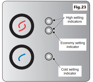
Selector Mode Indicators
Next to each control button there is an indicator that lights when the button is pressed, (fig.23) indicating which shower mode is in operation. On the high setting both indicators next to the upper button are lit. On the economy setting, the lower indicator only is lit.
Phased Shutdown
In use, when the Start/Stop button is pressed, power is switched off to the elements. Water will continue to flow for a few seconds, flushing out any remaining hot water. This makes sure the next immediate user will not receive a slug of hot water if standing under the showerhead when starting the shower.
Temperature Limiter
During normal operation if an overheat temperature is sensed, power to the elements will be reduced. Water will continue to flow. When the temperature has cooled sufficiently power to the elements will be automatically restored to the setting at the time of interruption.
Warning! This appliance is not intended for use by persons (including children) with reduced physical, sensory, or mental capabilities, or lack of experience and knowledge, unless they have been given supervision or instruction concerning use of the appliance by a person responsible for their safety. Children should be supervised to ensure that they do not play with the appliance.
WARNING! DO NOT use abrasive or aggressive cleaning products when cleaning the shower as they may damage the unit.
Safety Cut-Out
The unit is fitted with a non-resettable thermal cut-out safety device. In the event of abnormal operation which could cause unsafe temperatures within the unit, the device will disconnect the heating elements. It will require a visit from a qualified engineer to determine the nature of the fault and replace the safety device, once the unit has been repaired.
Setup Guide
Installing the Trion TESKIT09CH Kito Electric Shower is a straightforward process that can be completed in a few simple steps. First, ensure that the unit is installed by a qualified electrician in accordance with local regulations. Next, connect the water supply to the unit and secure it in place. Finally, connect the electrical supply and test the unit to ensure it is functioning properly. Always refer to the user manual for detailed instructions and safety precautions.
CLEANING
Triton Showers recommend that all products are cleaned using warm, soapy water. Do not use abrasive or aggressive chemical cleaning products as this may affect the product surface finish and invalidate your guarantee.
Instructions for Installers and Service Engineers Only
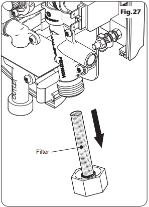
CLEANING THE INLET FILTER
It is recommended that the filter is periodically cleaned in order to maintain the performance of the shower. It is essential that this operation is carried out by an installer or service engineer.
IMPORTANT: Before servicing, switch off both the electricity supply and water supply at the mains. The inlet filter is situated in the side of the inlet pipe (fig.27 ). To gain access to the filter, remove the trim plate and then unscrew the retaining nut from the side of the inlet pipe. When cleaning the filter, do not use a sharp object, as it will cause damage. It is preferable to use an old toothbrush or similar. When refitting the filter Do not overtighten the filter cap.
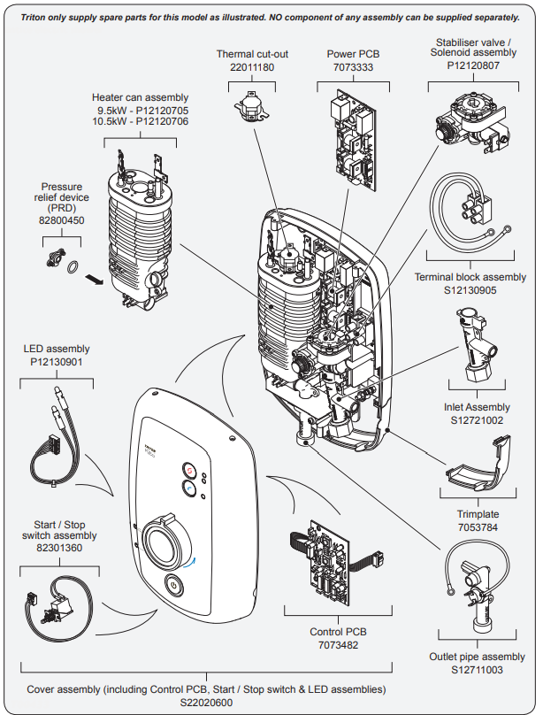
Spare Parts
FAULT FINDING
IMPORTANT: Switch off the electricity at the mains supply and remove the circuit fuse before attempting any fault finding inside the unit.
| Problem/Symptom | Cause | Action/Cure |
|---|---|---|
| 1. Shower inoperable, no water flow. | 1.1 Interrupted power supply. | 1.1.1 Blown fuse or circuit breaker. Check supply. Renew or reset fuse or circuit breaker. If it fails again, consult a qualified electrician. |
| 1.1.2 Power cut? Check other appliances and if necessary, contact local Electricity Supply Company. | ||
| 1.2 No mains water supply to shower. | 1.2.1 Check if isolating valves are fully open. Check for a blocked inlet filter or in pipework. | |
| 1.3 Unit malfunction. | 1.3.1 Have unit checked. Ring Customer Service. | |
| 2. Water too hot. | 2.1 Not enough water flowing through the shower. | 2.1.1 Increase flow rate via temperature control. |
| 2.1.2 Blocked showerhead – clean or replace blocked sprayplate in showerhead. | ||
| 2.2 Blockage in supply. | 2.2.1 Check if stop valves are fully open. Check for blockage in inlet filter. | |
| 2.3 Increase in ambient water temperature. | 2.3.1 Readjust flow rate to give increased flow. | |
| 2.3.2 Select 'economy' power. | ||
| 3. Water temperature cycling hot/cool at intervals. | 3.1 Heater cycling on thermal cut-out. | 3.1.1 See 'Water too hot' causes 2.1, 2.2, and 2.3 and their appropriate action/cures. If it continues, contact Triton Customer Service. |
| 4. Water too cool or cold. | 4.1 Too much flow. | 4.1.1 Reduce flow rate via temperature control. |
| 4.2 Water pressure below minimum required (see rating label). | 4.2.1 Is water supply mains or tank fed? If tank fed, replumb to mains water supply or see 4.2.4. | |
| 4.2.2 Check if stop valves are fully open. | ||
| 4.2.3 Check if a blockage in the inlet filter. | ||
| 4.2.4 If it is a mains supply, check that the mains water stop valve is fully open and that there are no other restrictions in the supply while the shower is in use, or see 4.2.4. | ||
| 4.2.5 Contact Triton Customer Service for advice. | ||
| 4.3 Reduction in ambient water temperature. | 4.3.1 Readjust flow rate to give reduced flow. | |
| 4.3.2 Select 'high' power. | ||
| 4.4 Electrical malfunction or safety cut-out operated. | 4.4.1 Have the unit checked by a suitably qualified electrician or contact Triton Customer Service. | |
| 5. Shower varies from normal temperature to cold during use. | 5.1 Water pressure has dropped below minimum required. | 5.1.1 Wait until the water pressure resumes to normal. |
| 6. Pressure relief device has operated (water ejected from PRD tube). | 6.1 Blocked showerhead. | 6.1.1 Clean or replace blocked sprayplate in the showerhead and fit new PRD. |
| 6.2 Twisted/blocked flexible shower hose. | 6.2.1 Check for free passage through the hose. Replace the hose if necessary and fit new PRD. | |
| 6.3 Showerhead not removed while commissioning. | 6.3.1 Fit new PRD. Commission the unit with the showerhead removed. | |
| 6.4 Water pressure above specified maximum for unit (see rating label). | 6.4.1 Fit pressure reducing valve to the inlet and then fit new PRD. | |
| 7. Shower fails to shut off flow when Start/Stop button is pressed. | 7.1 Faulty Start/Stop switch. | 7.1.1 Replace switch. |
| 7.2 Debris in the solenoid valve. | 7.2.1 Replace solenoid valve. | |
| 7.3 Unit malfunction. | 7.3.1 Have the unit checked. Ring Customer Service. |
Guarantee
Triton guarantees this product against all mechanical and electrical defects arising from faulty workmanship or materials for a period of two years for domestic use only, from the date of purchase, provided that it has been installed by a competent person in full accordance with the fitting instructions.
Pros & Cons
Pros
- Powerful 9.5 kW thermostatic heating element
- Phased Shutdown technology for prolonged unit life
- Rub-clean showerhead for easy cleaning
- Sleek and modern chrome finish
Cons
- May require professional installation
- May experience issues with water pressure
Customer Reviews about Trion TESKIT09CH Kito Electric Shower
Customers have praised the Trion TESKIT09CH Kito Electric Shower for its powerful heating element, stylish design, and easy-to-use controls. However, some have noted issues with water pressure and the need for professional installation. Overall, the unit has received positive reviews and is highly recommended for those looking to upgrade their bathroom shower experience.
Faqs
What safety features does the Trion TESKIT09CH Kito Electric Shower have?
What is included in the box with the Trion TESKIT09CH Kito Electric Shower?
How easy is it to clean and maintain the Trion TESKIT09CH Kito Electric Shower?
What is the showerhead spray pattern like on the Trion TESKIT09CH Kito Electric Shower?
How do I troubleshoot common issues with the Trion TESKIT09CH Kito Electric Shower?
What should I do if my Trion TESKIT09CH Kito Electric Shower stops working?
How long is the shower hose that comes with the Trion TESKIT09CH Kito Electric Shower?
How do I adjust the spray patterns on the Trion TESKIT09CH Kito Electric Shower?
How often should the Trion TESKIT09CH Kito Electric Shower be descaled?
How do I clean the exterior of the Trion TESKIT09CH Kito Electric Shower unit?
Leave a Comment