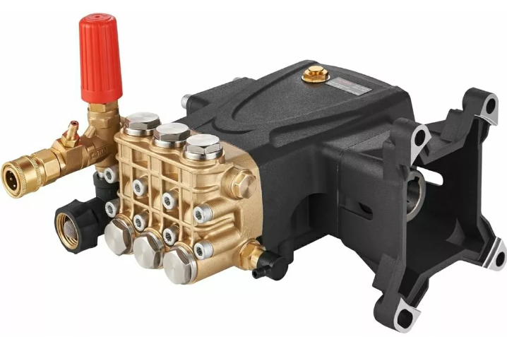
Vevor Pressure Washer Pump KBD2815G User Guide
Content
Introduction to the Vevor Pressure Washer Pump KBD2815G
The Vevor Pressure Washer Pump KBD2815G is a high-performance pump designed for efficient cleaning tasks, making it ideal for both residential and commercial use. The cost of the Vevor Pressure Washer Pump KBD2815G is approximately $150. With a powerful motor and durable construction, this pump delivers impressive water pressure to tackle tough grime, dirt, and stains on various surfaces, including driveways, patios, and vehicles. Its user-friendly design ensures easy installation and operation.
Specifications
- Power: 2800 PSI / 2.5 GPM
- Material: Durable Aluminum Alloy
- Connection Type: 3/8" Quick Connect
- Oil Capacity: 20oz
- Weight: Approximately 15 lbs
- Dimensions: 12" x 8" x 6"
- Compatibility: Universal fit for most pressure washers
Information
Identifies useful and important information or procedures that should be borne in mind.
Pump and manufacturer identification
Data plate
The data plate shown here,containing essential information for safe operation, is affixed to every pump.
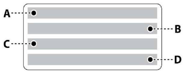
- L/min/GPM
- MPa/psi
- RPM
- Kw
TECHNICAL INFORMATION
General description
The pump is designed and constructed to pump and compress liquids at high pressure in industrial applications.The pumping action is provided by a series of pistons connected to the drive shaft by connecting-rods.
When in operation,the pistons perform an axial stroke inside the head, where the intake and delivery ducts are fitted with valves that allow the liquid to pass in one direction only.
Main components
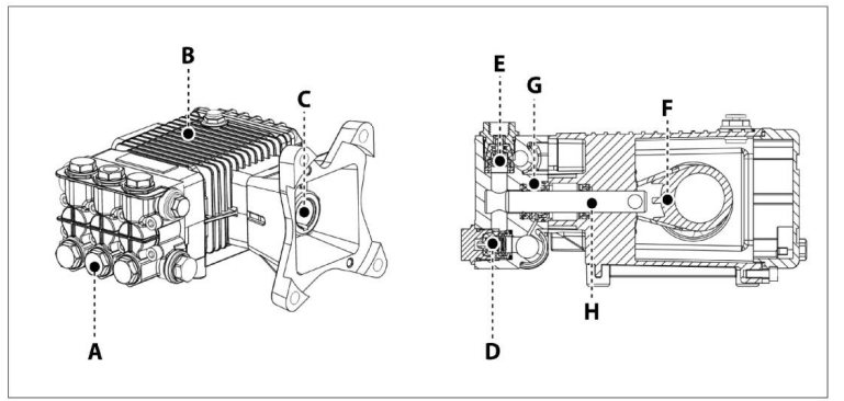
- A). Head
- B). Pump body
- C). Crankshaft
- D). Intake valve
- E). Delivery valve
- F). Guide
- G). Seal
- H). Piston
Intended uses
The pump is designed and built for incorporation in machinery and plants(machinery for washing raw materials,fnished products,etc.).
The pump must be used in a manner appropriate to its technical data(see"Technical Data"),and must not be modified or improperly used.
Misuses
- Do not put the pump into service until the plant or machinery in which it is incorporated has been declared compliant with the relevant nationaland local legal requirements.
- Do not use the pump in a potentially explosive atmosphere.
- Do not use the pump for flammable,toxic or corrosive liquids,or those with unsuitable density.Do not take in liquids at temperatures higher than those specifed in the technical data.
- Do not use the pump for the supply of drinking water.
- Do not use the pump on products for human consumption.
- Do not use the pump on pharmaceutical products.
Residual risks
Even if the safety regulations and information provided in the manual are complied with,the residual risk described below is still present during the use of the pump.
Thermal hazard: Depending on the temperature of the liquid pumped,the pump may reach high temperatures when in operation.The designer of the installation must therefore bear this in mind and provide the appropriate measures and warning signs for staff.
Technical Data
The technical and performance data are stated on the cover.
The pump's intake circuit must include a filter having a capacity at least twice the pump's delivery rate, which must not cause restrictions or head losses. The recommended degree of filtration is 50-80 mesh.Maximum intake vacuum-0.25 bar, measured at the pump intake.
Overall dimensions
The illustrations showing the overall dimensions are provided in the annexes.
Environmental operating limits
The pump operates correctly at an ambient temperature between 10 and 35°C, with a relative humidity of 80%.
| Product Specifications and Packing List | ||
| Model | KPD2110G | KBD2815G |
| Working Pressure | 3200 PSI | 4000 PSI |
| Gun Closing Pressure | 3700 PSI | 4400 PSI |
| Factory set pressure | 2500-2600 PSI | 3500-3600 PSI |
| Matching Horsepower | 6.5-7/HP | 13-15/HP |
| Maximum Flow | 2.5 GPM | 4.0 GPM |
| Adaptive Model | 208~230CC | 420~460cc |
Packing List | 1 x Pressure Washer Pump;1 x Siphon;4 x Bolts; 1 x Vent Plug;1 x Shaft Key;4 x Flat Pads 4 x Spring Washers;1 x Manual | |
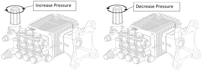
Note: To match engines with different power, the factory set pressure will be less than the rated maximum pressure. Just adjust the pressure limiting valve if you need to increase the pressure.
SAFETY INEORMATION
General safety rules
- Most workplace accidents and injuries are caused by carelessness and failure to comply with common sense and safety rules.
- In most cases,accidents can be avoided by predicting their possible causes and proceeding with the necessary care and attention.
- A careful operator who follows the rules is the best guarantee against accidents.
- Before installing and using the pump,the operators and other staff must read and understand the instructions in the manual provided and the details of the installation design.
- Do not tamper with,disarm or bypass the safety devices as this may cause serious threats to health and safety. Do not release pollutants into the environment.
- Dispose of waste in accordance with statutory requirements.
- Before performing any procedure,adopt appropriate safety measures in accordance with the relevant statutory occupational safety requirements and comply with the safety regulations in the manual.
HANDLING AND TRANSPORT INSTRUCTIONS
- Safety recommendations for handling and lifting
- Before starting the operations, organize the intended working area so that the materials can be lifted and handled in safety.
- Unloading, loading, handling and lifting operations must be carried out by skilled,authorized, and specifically trained staff.
- During lifting and handling operations, the people not involved in the operations must remain at a safe distance.
- For lifting, use hooks and ropes which are free from damage and appropriate for the load to be lifted.
Packaging description and unpacking
- The packaging normally consists of a cardboard box for easy, safe transport.
- Depending on the quantity of goods to be shipped and the place of destination, packages may be fixed on a pallet for easier lifting and handling.
- Check the weight of the item on the transport documents to allow the use of suitable lifting equipment.
- When unpacking, check that all components are present and intact. If items are missing or damaged, contact the dealer or manufacturer to agree on the procedures to be followed.
- The packaging material must be disposed of appropriately in accordance with the relevant statutory requirements.
Transport
The pump may be shipped by a variety of means of transport(road, rail,sea or air) depending on its destination. Secure the packaging firmly to the vehicle during transport to prevent random movement.
Storage
- In the event of a lengthy period out of use, place the pump(in its packaging if possible or otherwise protected) under cover, protected from the weather.
- Do not store in places where the ambient conditions might impair the pump's operating condition over time.
Description
The Vevor Pressure Washer Pump KBD2815G boasts a powerful 2800 PSI and 2.5 GPM output, making it ideal for tackling tough cleaning jobs. Constructed from durable aluminum alloy, this pump is built to last and withstand the rigors of frequent use. The 3/8" quick connect feature ensures easy and secure connections, while the 20oz oil capacity ensures smooth operation over extended periods.
The pump's compact design and lightweight construction make it easy to handle and store. Its universal compatibility means it can be used with a wide range of pressure washers, providing users with flexibility and convenience.
NSTALLATION INSTRUCTIONS
Safety recommendations for installation
- Take all possible precautions to allow the pump to be installed in a safe, risk-free manner.
- All installation phases must be taken into consideration when designing the machinery or plant in which the pump is to be installed.
- The design must consider all mounting points, the means of transmission of the energy sources, and the protective and safety devices required by the relevant regulations to prevent the risk of injury.
Installation
- The mechanical connection between the pump and the motive power source may be made by means of a pulley and belt, or a flexible coupling, or through a direct flanged connection to the motive power source.
- The crankshaft may turn in either direction.
- The water supply connection can be made equally well to the intakes on the right or left of the pump(see diagram). Only connect the pump to filtered, clean water sources.
- Unscrew the plugs fitted on the various ports in the factory by the manufacturer, and screw the plugs onto the ports not used, depending on connection requirements.
- Replace the oil plug (A), used for shipment with the breather plug (B)supplied.
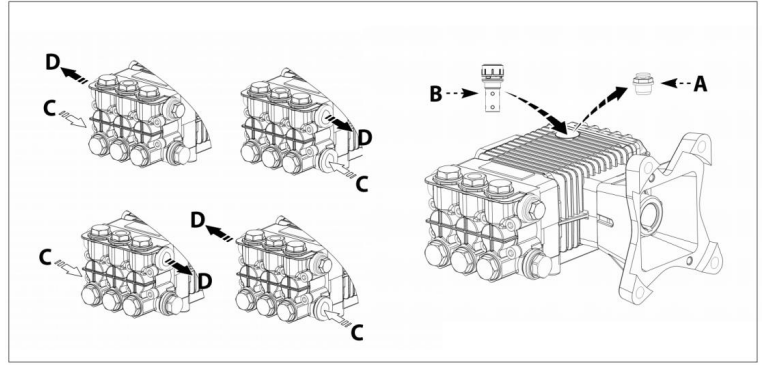
- Temporary oil plug
- Oil plug with breather
- Intake port
- Delivery port
Mounting the pump
The pump must be installed on a horizontal surface with no flexible components between it and the mounting surface. The illustration shows the maximum permitted pump installation angle beyond which proper lubrication of the crank mechanism is not ensured. Secure the pump with screws of suitable diameter and length, fixing them through the holes provided in the pump body.

General guidelines on water supply connection
The pump's water supply connection can be made in one of the ways listed below.
- Connection to the mains water supply.
- Connection to a tank(gravity-feed).
- Connection to an external pump(force-feed).
The following requirements must be met for all types of connection.
- The pump must be supplied by means of a crush-proof hose of suitable diameter for the pump's intake connection(see "Technical Data").
- There must be no restrictions or kinks in the hose.
- A suitable filter must be installed at the pump intake(see "Technical Data").
- All connections between the unions and the intake line must be sealed to prevent the pump from sucking in the air.
- The connections and pipes must be suitable for the operating pressure and the pump delivery rate, and must comply with the relevant regulations.
- To ensure operating safety install a relief valve(by-pass valve) suitable for the pump's technical data and with a suitable setting downstream of the pump.
- The relief valve dump line must never be connected to the pump intake line.
- Install a pressure damper downstream of the pump to minimise the water hammer effect in the delivery pipeline.
Connection to the mains water supply
The connection must comply with the recommendations provided.
- The mains water system must have a flow rate twice the pump's rated delivery rate and a pressure of 2-3 bar.
- Adopt all the precautions described in the“General Guidelines on Water Connections" section.
The following is a simplified illustration of the layout for connection of the pump to the mains water supply.
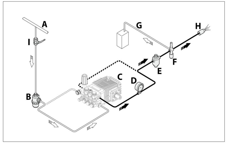
- Mains water supply
- Intake filter
- High-pressure pump
- Pressure gauge
- Pressure damper
- Relief valve (by-pass valve)
- Dump pipeline
- Nozzle
- Shut-off valve
Connection to a tank(gravity-feed)
The connection must comply with the recommendations provided.
- The pump must be installed in a position below the tank intake (with a positive head).
- The tank must have baffles to prevent water splashes and its capacity must be at least 10 times greater than the pump's rated displacement.
- The vacuum measured directly at the pump intake port must not exceed 0.1 bar and the water temperature must not be above 30℃ .
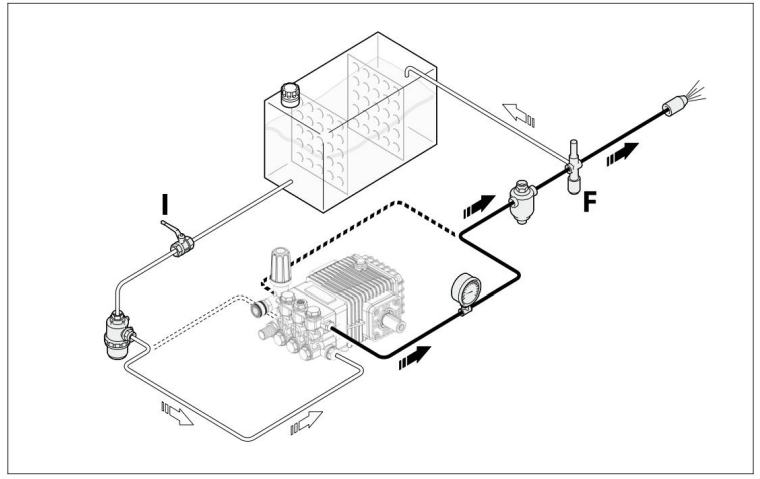
- Adopt all the precautions described in the"General Guidelines on Water Connections" section. The following is a simplified illustration of the layout for the connection of the pump to a tank.
.png)
- Tank
- Intake filter
- High pressure pump
- Pressure gauge
- Pressure damper
- Relief valve(by-pass valve)
- Dump pipeline
- Nozzle
- Shut-off valve
Connection to an auxiliary pump (force-feed)
The connection must comply with the recommendations provided.
- The auxiliary pump must have a flow rate twice the high-pressure pump's rated delivery rate and an operating pressure of 2- 3 bar.
- Adopt all the precautions described in the“General Guidelines on Water Connections" section.
The following is a simplified illustration of the layout for the connection of the pump to an auxiliary pump.
.png)
- Tank
- Intake filter
- Auxiliary pump
- High-pressure pump
- Pressure gauge
- Pressure damper
- Relief valve (by-pass valve)
- Dump pipeline
- Nozzle
- Shut-off valve
Safety recommendations for use
- Before start-up, the operator must perform the necessary safety checks.
- In the event of leaks from the pressurized pipes ,stop the pump at once and remove the cause of the leak.Do not operate the pump above the limits set by the manufacturer to increase its performance.
- lf the system is to be shut down with ambient temperatures close to 0℃, run the pump without water for 10 seconds with the end of the delivery pipeline open to empty the system and pump of water and prevent ice from forming.
Starting and stopping the pump when supplied by the mains water system
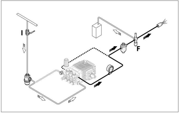
To start the pump,proceed as described below.
- Open the shut-off valve (I) .
- Open the by-pass valve (F) to depressurise the delivery pipeline.
- Start the pump and run it for a few minutes with no pressure.
- Adjust the by-pass valve (F) to obtain the pump's operating pressure.
To stop the pump,proceed as described below.
- Open the by-pass valve (F) to discharge the pressure.
- Stop the pump.
- Close the shut-off valve (I) .
Starting and stopping the pump when supplied by gravity-feed
To start the pump,proceed as described below.
- Open the shut-off valve (I) .
- Open the by-pass valve (F) to depressurise the delivery pipeline.
- Start the pump and run it for a few minutes with no pressure.
- Adjust the by-pass valve (F) to obtain the pump's operating pressure.
To stop the pump,proceed as described below.
- Open the by-pass valve (F) to discharge the pressure.
- Stop the pump.
- Close the shut-off valve (I) .
Starting and stopping the pump when supplied by an auxiliary pump
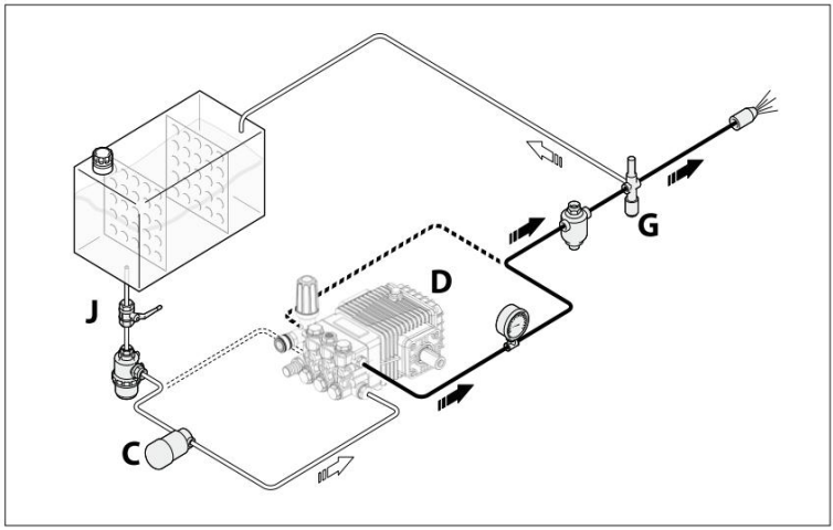
To start the pump,proceed as described below.
- Open the shut-off valve (J) .
- Open the by-pass valve (G) to depressurise the delivery pipeline.
- Start the auxiliary pump (C) .
- Start the pump (D) and run it for a few minutes with no pressure.
- Adjust the by-pass valve (G) to obtain the pump's operating pressure.
To stop the pump,proceed as described below.
- Open the by-pass valve (G) to discharge the pressure.
- Stop the pump (D) .
- Stop the auxiliary pump (C) .
- Close the shut-off valve (J) .
Setup Guide
To set up the Vevor Pressure Washer Pump KBD2815G,
- Start by ensuring all components are included and undamaged.
- Connect the pump to your pressure washer using the 3/8" quick connect fitting. Make sure all connections are secure and tightened properly.
- Fill the oil reservoir with the recommended type and amount of oil.
- Finally, test the pump by running it through a few cycles to ensure proper operation.
MAINTENANCEIN STRUCTIONS
Safety recommendations for maintenance
- Before doing any maintenance work, depressurise the water system and isolate the pump from all energy sources.
- When the jobs are done, before restarting the pump, check that no tools, rags or other materials have been left close to moving parts or in hazardous zones.
- Replace any excessively worn components with original parts and use the lubricants recommended by the manufacturer.
- Dispose of the worn-out components and lubricants in accordance with the relevant statutory requirements.
- Carry out the routine maintenance procedures specifed by the manufacturer to keep the pump safe and performing well.
| Scheduled Service Table | |||
Every working day | Filter | Inspect filter cartridge | See"Inspecting the flter" |
| Pump | Oil level check | See"Checking the oil leve!" | |
Every 50 working hours | Connection of pump to power source (pulley,belt,coupling) | Inspection | |
| Pump | Inspect mounting | See"Inspecting thepump mounting" | |
| Pipes and connections | Inspection | See"Inspecting theconnections and pipes" | |
| Pump | Oil change(1) | See"Changing the oil" | |
| Pump | Oil change | See"Changing the oil" | |
Every 500 working hours or every year | Pump gaskets | Replacement | Contact an authorised service centre |
Every 1000 working hours | Valves | Replacement | Contact an authorised service centre |
| Filter | Inspect filter cartridge | See"Inspecting the flter" | |
- This interval refers to the first oil change only
Table of lubricants
- The pump is delivered complete with oil, with the characteristics stated on the data plate.
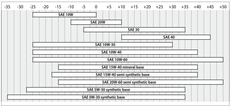
- When changing the oil, use an oil suitable for the conditions in the operating environment (see recommendations provided in the annexes and see"Environmental operating limits").
- The correct lubricating oil viscosity depends on the external temperature.
Use the graph to select the degree of viscosity best suited to the temperatures of use.
Inspecting the pump mounting
Check that the pump's fixing screws have not become loose. If necessary, tighten them with the driving torque stated in the installation design.
Inspecting the connections and pipes
- Inspect the connections for leaks.
Leaks can normally be dealt with by tightening the connections properly. If leaks from the intake pipeline connections are noticed, the seals must be repaired.
- Inspect the hoses.
lf the pipes show signs of aging, breakage, swelling, rubbing, etc., they must be replaced.
Inspecting the Filter
Inspect the filter cartridge.
- If the flter cartridge is fouled or damaged, refer to the filter manufacturer's instructions for details on how to restore the filter cartridge to its original filtering condition.
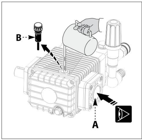
Checking the oil level
- Check the oil with the pump level and cold.
- Check the amount of oil through the level gauge (A).
- If necessary, top up with oil with the characteristics specified in the "Lubricants table".
To top up with oil proceed as described below.
- Unscrew the plug(B) and pour oil in until it is halfway up the level gauge (A).
Screw on the plug (B).
Changing the oil
- Position the machine in which the pump is incorporated perfectly level, with the pump slightly warm.
- Do not release oilinto the environment.
- Dispose of spent oilin accordance with statutory requirements.
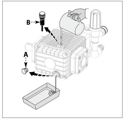
To change the oil, proceed as described below.
- Position a receptacle of suitable capacity to collect the spent oil.
- Unscrew the drain plug (A)and allow all the oil to flow out.
- Screw on the drain plug( A).
- Unscrew the filler plug (B).
- Pour in the fresh oil through the fller hole until the correct level is reached (see "Checking the oil level").
Screw on the fller plug( B).
Lengthy pump lay-offs
If the pump is to be unused fora long time, proceed as described below.
- Run the pump with clean water for a few minutes.
- Operate the pump without water for 10 seconds with the end of the delivery pipeline open to empty the pump and the delivery circuit and prevent scaling.
- Flush the pump with water and solvents authorized by the relevant laws.
- Dry the pump with a pressurized air jet.
- Protect the pump from the weather.
Putting the pump back into service
Before putting the pump back into service after a long period out of use, check the oil level and the tightness of the mounting screws.
Scrapping the pump
- The pump must be scrapped by skilled staff, in compliance with the statutory requirements on occupational safety.
- The dismantled components must be sorted by the type of materials from which they are made. Do not dump pollutants such as seals and lubricants into the environment.
- Dispose of them in accordance with statutory requirements with regard to waste disposal and recycling.
Troubleshooting
The information provided is intended to provide guidance on how to deal with malfunctions that may occur during use.
Some of these procedures may be carried out by skilled staff, while others have to be performed at specialized service centres since they require the use of specific equipment as well as detailed knowledge of repair operations.
Problem | Cause | Remedy | ||||||
Pump does not reach the specified pressures |
Pump sucking air | Restore the tightness of the intake line | ||||||
Intake flow rate insufficient | Increasethe size of the intake pipelines | |||||||
| Remove any kinksfrom the pipes | ||||||||
Increase the filtercapacity or clean the filtercartridge | ||||||||
Increase speed | the | rpm | to | the | rated | |||
Worn intake and delivery valves | Replace the valves(1) | |||||||
By-pass valve seatworn | Replace the valve | |||||||
Worn | gaskets | Replace the gaskets(1) | ||||||
Unsuitable, worn nozzle | Replace | nozzle |
|
|
| |||
lrregular variations in pressure | Worn intake and delivery valves | Replace the valves(1) | ||||||
Valves blocked by dirt | Clean the valves(1) | |||||||
Air being suckedinto system | Restore the tightness of the intake pipeline connections | |||||||
Worn | gaskets | Replace the gaskets(1) | ||||||
Vibrations on pipes | Valves | jammed | Replace the valves(1) | |||||
By-pass valve malfunction | Replace the by-pass valve | |||||||
By-pass valve dumpline too small | Increase size of by-pass valve dump line | |||||||
Pressure damper flat | Restore pressure damper to correct inflation pressure | |||||||
Pump sucking air | Restore the tightness of the intake line | |||||||
Pressure drop | Nozzle | worn | Replace | nozzle |
|
|
| |
Worn intake and/ordelivery valves | Replace the valves(1) | |||||||
Valves blocked by dirt | Clean the valves(1) | |||||||
By-pass valve seatworn | Replace the valve | |||||||
Worn | gaskets | Replace the gaskets (1) | ||||||
Pump noisy | Air being suckedinto system | Restore the tightness of the intake pipeline connections |
Intake and/ordelivery valve springs broken or collapsed | Replace the valves(1) | |
| Valves blocked by dirt | Clean the valves(1) | |
| Worn bearings | Replace the bearings(1) | |
Intake liquid temperature too high | Reduce liquid temperature | |
Pump overheating | High pump operating pressure | Reduce the pressure to the rated values |
| Drive belts tootaut | Restore correct belttension | |
Pulley or drive coupling alignment poor | Restore the correct alignment | |
Water in oil | Guide piston gaskets worn | Replace the gaskets(1) |
| High humidity percentage in air | Change the oil twice as often (than stated in"Routine Maintenance"table) | |
| Worn gaskets | Replace the gaskets(1) | |
Oil leaks fromdump lines underneath the pump | Worn gaskets | Replace the gaskets(1) |
| Worn pistons | Replace the pistons(1) | |
Oil leaks fromdump lines underneath the pump | Guide piston gaskets worn | Replace the gaskets(1) |
- Operations that must be carried out at an authorized service centre
There are any minor changes to the numbers included in the user manual without prior notice.
Pros & Cons
Pros:
- High-pressure output for efficient cleaning
- Durable construction for long-lasting performance
- Easy installation with universal compatibility
- Compact and lightweight design for easy handling
- Cost-effective compared to other high-performance pumps
Cons:
- Requires regular maintenance to ensure optimal performance
- May require additional support for heavy-duty use
- Limited customer support in some regions
Customer Reviews
Users of the Vevor Pressure Washer Pump KBD2815G have generally praised its performance and durability. Many have noted its ability to handle tough cleaning tasks with ease, while others appreciate its easy installation process. However, some users have reported issues with customer support and the need for regular maintenance.
A common complaint is the lack of detailed instructions in the user manual, which can make troubleshooting more challenging.
Faqs
What is the maximum pressure output of the Vevor?
Is this pump compatible with all pressure washers?
How often should I maintain the Vevor?
What type of oil should I use in the Pressure KBD2815G?
Can I use this pump for heavy-duty industrial cleaning?
How do I troubleshoot a lack of pressure issue with my Vevor KBD2815G?
How do I assemble and configure the Washer Pump?
Where can I find replacement parts for the Vevor Pressure Washer Pump?
Leave a Comment
