Witmotion Angle Storage Sensor WT901SDCL User Guide
Content
Introduction
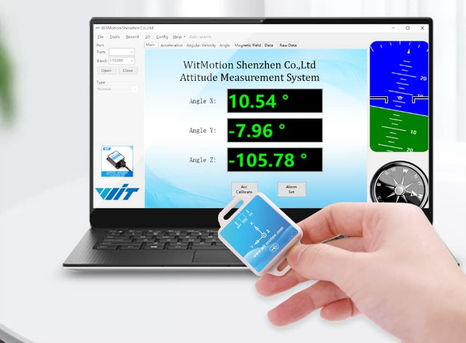
The Witmotion Angle Storage Sensor WT901SDCL is a versatile 9-axis accelerometer and inclinometer designed for precise angle measurement and motion tracking. It features high accuracy with a 0.05° angular resolution, making it suitable for various applications, including robotics and engineering projects. The sensor supports both online and offline usage, providing flexibility in data collection. Priced at $53.99, it comes with essential accessories like a 16GB SD card and a charging cable.
Features
- voltage: 3.3V ~ 5V 2,
- current: <40mA
- Battery capacity: 200mAh
- Battery voltage: 3.7V
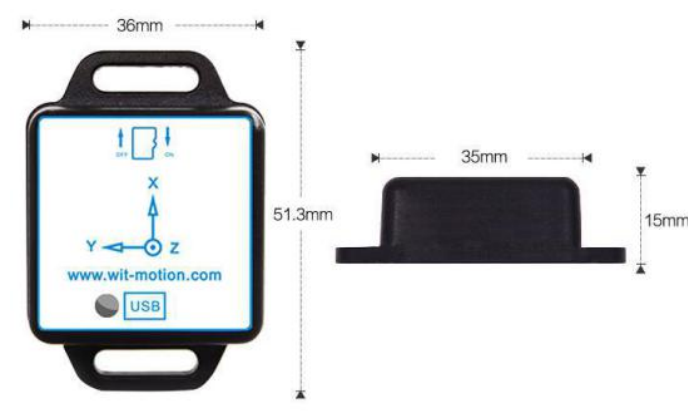
- Volume: 51.3mm X 36mm X 15mm
- Measurement dimensions: acceleration: 3D, angular velocity: 3D, magnetic field: 3D, angle:3D.
- Range: Acceleration: ± 2/4/8/16 g (optional), angular velocity: ± 250/500/1000/2000 ° /s (optional), X, Z axis ± 180 °, Y axis ± 90 °.
- Stability: Acceleration: 0.01g, angular velocity 0.05 ° / s.
- Stability of attitude measurement: 0.01 °.
- Data output content: time, acceleration, angular velocity, angle, magnetic field, port status, quaternion.
- Data output frequency: 0.1Hz ~ 200Hz.
- Data interface: serial port (TTL level, baud rate support 2400, 4800, 9600, 19200, 38400, 57600, 115200, 230400, 460800, 921600)
Detailed Specifications
The Witmotion Angle Storage Sensor WT901SDCL boasts several key features that make it a standout in its class. Here are some of its detailed specifications:
- Measurement Range: ±180 degrees
- Accuracy: ±0.5 degrees
- Resolution: 0.01 degrees
- Communication Interface: I2C, SPI, UART
- Power Supply: 3.3V to 5V
- Operating Temperature: -40°C to 85°C
- Storage Capacity: Up to 10,000 data points
Hardware Connection
Description
- The module integrates high-precision gyroscope, accelerometer, and geomagnetic field sensor. Using high-performance microprocessor, advanced dynamics calculation and Kalman dynamic filtering algorithm, it can quickly solve the module's current real-time motion attitude.
- The use of advanced digital filtering technology can effectively reduce measurement noise and improve measurement accuracy.
- The attitude solver is integrated into the module, and the dynamic Kalman filter algorithm can be used to accurately output the current attitude of the module in a dynamic environment. The attitude measurement accuracy is 0.05 degrees static and 0.1 degree dynamic. Some professional inclinometers!
- The module has a built-in voltage stabilization circuit, the working voltage is 3.3v ~ 5v, and the pin level is compatible with 3.3V / 5V embedded system, which is easy to connect.
- The module contains a battery, which can be used alone when fully charged.
- SDThe module has an SD card inside to record the measured data.
- Support serial TTL interface for users to choose the best connection method. The serial port speed is adjustable from 2400bps to 921600bps.
- Up to 200Hz data output rate. The input content can be arbitrarily selected, and the output rate can be adjusted from 0.1 to 200HZ.
Axial Description
As shown in the figure above, the axial direction of the module is shown on the upper icon, the X axis is upward, the Y axis is left, and the vertical module is outward.
Is the Z axis. The direction of rotation is defined by the right-hand rule, that is, the thumb of the right hand points to the axial direction, and the direction in which the four fingers are bent is the direction of rotation around the axis. The X-axis angle is the angle around the X-axis rotation direction, the Y-axis angle is the angle around the Y-axis rotation direction, and the Z-axis angle is the angle around the Z-axis rotation direction.
Hardware connection method
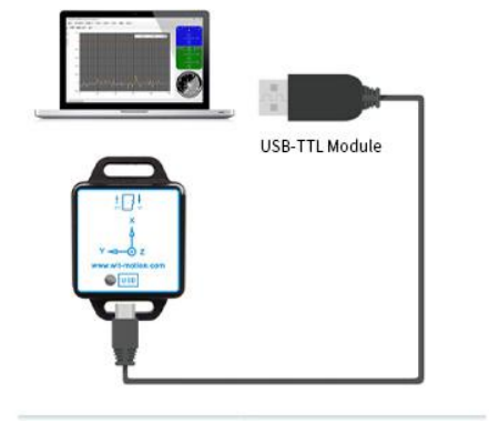
Connecting to a computer
This product has an attached cable that connects the computer and the product. Please use the cable that comes with the product. Use the data cable to connect the product (the SD card is plugged into the module before the module starts to work).
Indicator status
- The product is connected to the power supply. At this time, the power indicator (red) indicator is always on, indicating that the product is charging. The red light will go out after charging is completed.
- After inserting the SD card for about 1 second, the blue light flashes, indicating that the SD card is recording data.
Software usage
How to use
Note that users who cannot run on the upper computer should download and install .net framework4.0: http://www.microsoft.com/en-us/download/details.aspx?id=17718
Connect to the computer via the USB cable attached to the product and turn on the upper computer. After installing the driver CH340 corresponding to the serial port module, you can query the corresponding port number in the device manager, as shown in the figure:
The driver is CH340, as follows: http://pan.baidu.com/s/1o6Rleae?frm=fujian
Open the MiniIMU.exe software, in [Data Package / Upper Computer], click the serial port selection menu, and select the COM number you just saw in the device manager.
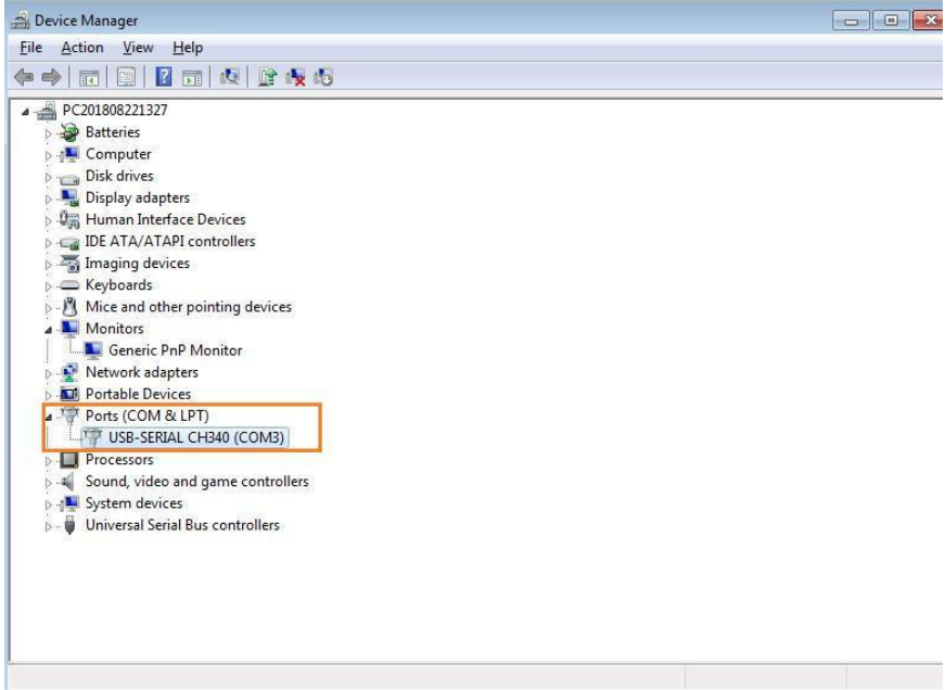
Open the software MiniIMU.exe, Click “Port” and select the com number you just saw in the device manager.
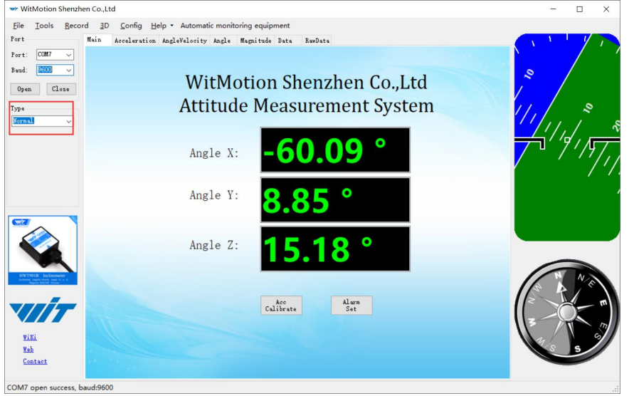
Click the “Type” and select model “Normal.
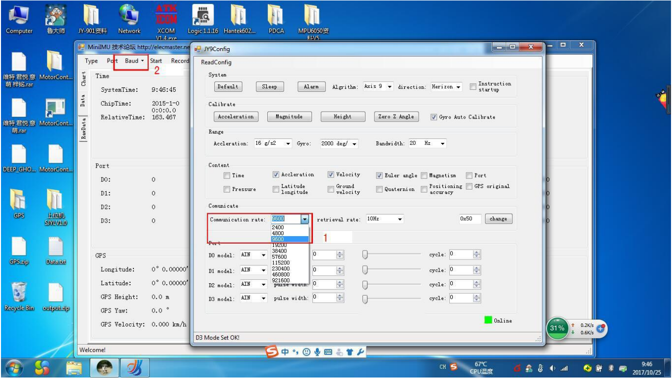
Click the “Baud” and select “9600”, after all those selections are completed, the software can display data.


Click the “3D” and you can bring up the three-dimensional display interface, which displays the three-dimensional posture of the module.

Restore factory settings
Command method operation method: Connect the WT901SDCL module and the computer through the cable that comes with the module, click the Settings tab, and click Restore Default. After restoring factory settings, power on the module again. (This method needs to know the baud rate of the module in advance, if the baud rate does not match the instruction will not take effect).
Module calibration
Note: The module calibration and configuration should be performed in the online state at the lower right corner of the configuration bar of the host computer, as shown in the figure below. Offline indicates that the host computer does not control the module.
Before using the module, you need to calibrate the module. The calibration of WT901SDCL module includes addition calibration and magnetic field calibration.
The 6-axis algorithm calibration includes Z-axis return to 0 and addition calibration.4.3 Module Calibration
Reminder: The module calibration and configuration should be carried out under the online state which displayed in the low right corner of the software configuration bar.
The module need to be calibrated before the module is used. The calibration of WT901 includes accelerometer calibration and magnetic calibration.
Accelerometer Calibration
The accelerometer calibration is used to remove the zero bias of the accelerometer. When the sensor is out of the factory, there will be different degrees of bias error. After manual calibration, the measurement will be accurate.
Methods as follow:
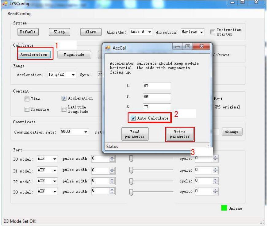
- Firstly keep the module horizontally stationary, in the “Config” of the software click “Acceleration” and a calibration interface will pop up.
- Check the “Auto Calculate” option, the software will automatically calculates the zero bias value and then click “Write parameter”
Magnetic Calibration
Magnetic field calibration is used to remove the magnetic field sensor's zero offset. Usually, the magnetic field sensor will have a large zero error when it is manufactured. If it is not calibrated, it will bring about a large measurement error and affect the accuracy of the Z-axis angle measurement of the heading angle.
Calibration methods as follow:
- When calibrating, first connect the module and the computer, and place the module in a place far away from the disturbing magnetic field (ie, more than 20 CM away from magnets and iron, etc.), and then open the upper computer software.
- In the settings page, click on the magnetic field button under the calibration bar to enter the magnetic field calibration mode. At this time, the MagCal window pops up. Click on the calibration button in this window.
- Then slowly rotate the module around the three axes, let the data points draw points in the three planes, you can rotate a few more times, and after you draw a more regular ellipse, you can stop the calibration. After the calibration is completed, click Write Parameters.
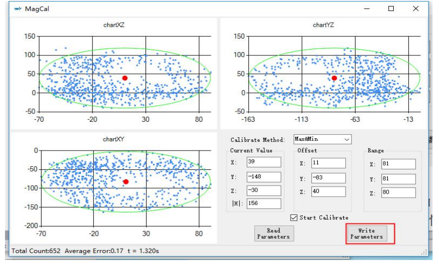
Note: The data points should be within the ellipse but not outside the ellipse. If you cannot draw the ellipse, please keep away from the magnetic field interference.
Video address:
https://www.youtube.com/channel/UCxBLgvYQNk-sGVDp42ch-Ug
Z axis To 0
Ps: If you want to avoid magnetic interference,you can change the algrithm to Axis 6,the you can use Z axis to 0
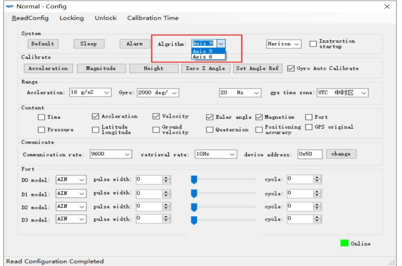
Reminder: Z axis to 0 is valid for JY61P only.
The z-axis angle is an absolute angle, and it takes the northeast sky as the coordinate system can not be relative to 0 degree.
Z axis to 0 is to make the initial angle of the z axis angle is relative 0 degree.When the module is used before and z - axis drift is large, the z - axis can be calibrated, When the module is powered on, the Z axis will automatically return to 0.
Calibration methods as follow: firstly keep the module static, click the “Config” open the configuration bar and then click “Zero Z Angle” option, you will see the the angle of the Z axis backs to 0 degree in the module data bar.


Gyroscope Automatic Calibration
The gyroscope calibration is to calibrate the angular velocity, and the sensor will calibrate automaticly.
Set Return Content
Setting method: The content of returned data can be customized according to the user´s needs, click “Config” to open configuration bar, and hook the data content option that you want. Take JY901 as an example, the default output of the module is acceleration, angular velocity angle and magnetic field.
Longitude and ground velocity information are effectively when connected to the GPS module. In order to get the correct data we need to set the content.

Set Return Rate
Setting methods: click “Config” to open configuration bar and than set the “retrieval rate” is 0.1HZ-200HZ optional.
The default return rate of the module is 10HZ, the highest return rate supports 200HZ. 10HZ refers to 10 packets returned every second. There contains 33bytes in a data packet in default.
Reminder: If there being a lot of return content and low baud rate of communication, the module will automatically reduce the frequency and output at a maximum allowable output rate. The default baud rate is 115200.

Set Baud Rate
Module supports multiple baud, 9600 default. Change baud rate only when the module connect to PC program successfully, choose the baud rate and Click “Change” button.
Reminder: After changing the baud rate, the module does not immediately take effect, need to re-power and then it will take effect.
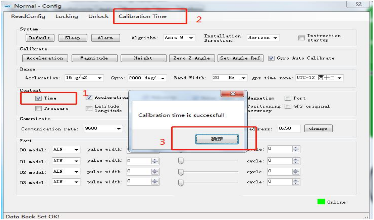
Calibration time
- Under Configuration-Time; check before the time button, the time of calibration is displayed in the data interface, and under time-on-chip time, only check to display the time.
- Setting method: On the host computer-configuration-calibration time, click to calibrate the time, the successful calibration will prompt the calibration time to be successful.
- Function: By calibrating the time, the time of the host computer is the same as the current time, and you can know when the data is recorded when recording the data.
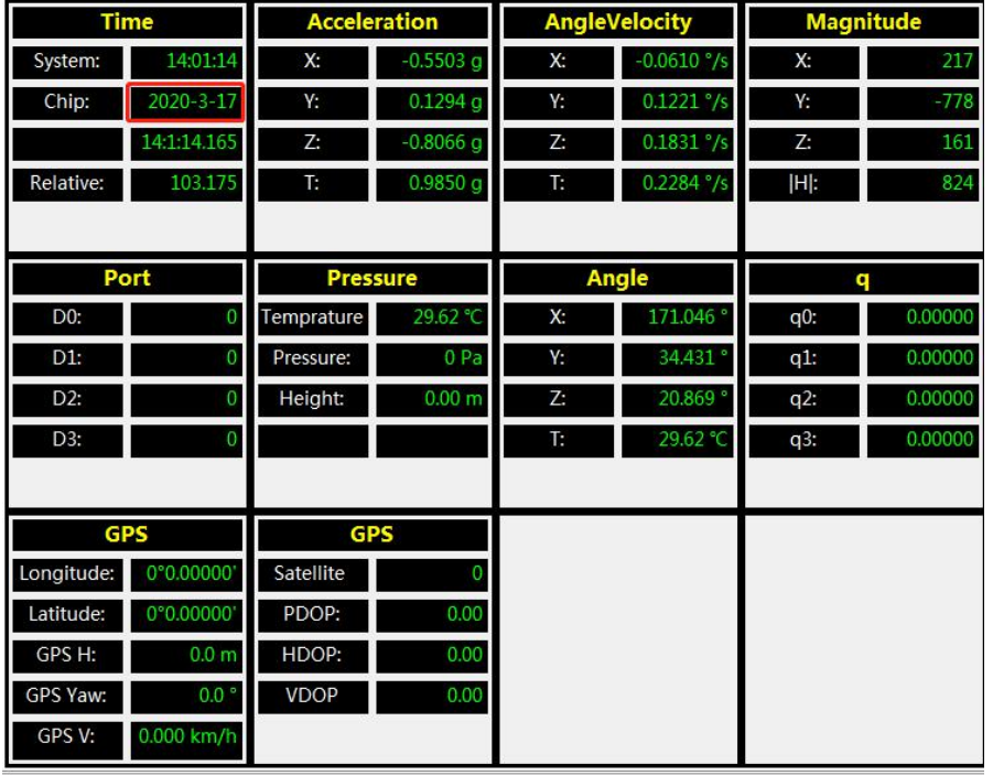
Data Recording
There is no memory chip in the sensor module, and the data can be recorded and saved in the software.
Method are as follows: Click “Record” and “Start” will save the data as a file.

The saved file is in the directory of the software Data.tsv:
The file begins with a value indicating the data. “Time” stands for time, “ax, ay, az” respectively represents the acceleration of X, Y , Z axis. “wx, wy, wz” respectively represents the angular velocity of X, Y, Z axis. “AngleX, AngleY, AngleZ” respectively represents the angle of the X, Y, Z axis. T represents the temperature.
Data can be imported into the Exel or analysis in Matlab. In the Matlab environment running xxx.m document and it can plot of the data.
Installation Direction
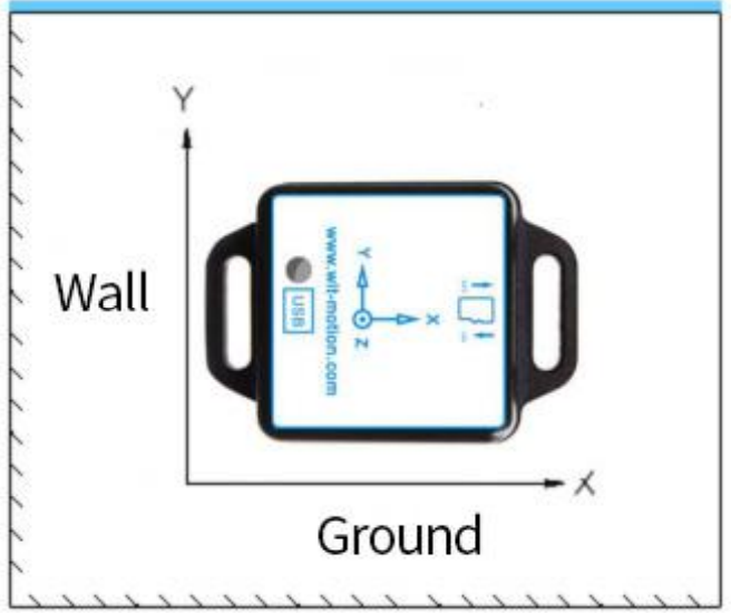
The default installation direction of the module is horizontal installation. When the module needs to be vertically placed, it can be installed vertically.
Vertical installation method: Put the module around X-axis rotation 90 degrees vertical placement. In the “Config” of the software, click “Vertical” option. The calibration can be used after the setup is completed.

Set Bandwidth
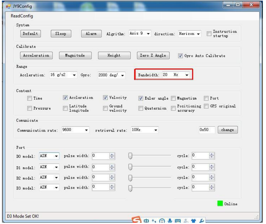
Bandwidth: The module outputs only the data within the measurement bandwidth, and the data which is larger than the bandwidth will be filtered automatically.
In the “Config” of the software, click “Bandwidth” option to set it, the default setting is 20HZ.
Six axis/ Nine axis Algorithm
- JY61P uses the 6 axis algorithm, and the z axis angle is calculated mainly according to the angular velocity integral.
- JY901 uses the 9 axis algorithm, the z axis angle is mainly calculated according to the magnetic field, there will be no drift phenomenon.
- When the JY901 environment is disturbed by magnetic field, the 6 axis algorithm can be used to detect the angle.
- Nine axis algorithm to use 6 axis algorithm: in the PC configuration bar, the algorithm changed to "Axis6", and then additional calibration and Z axis zeroing calibration. The calibration will be ready for use.
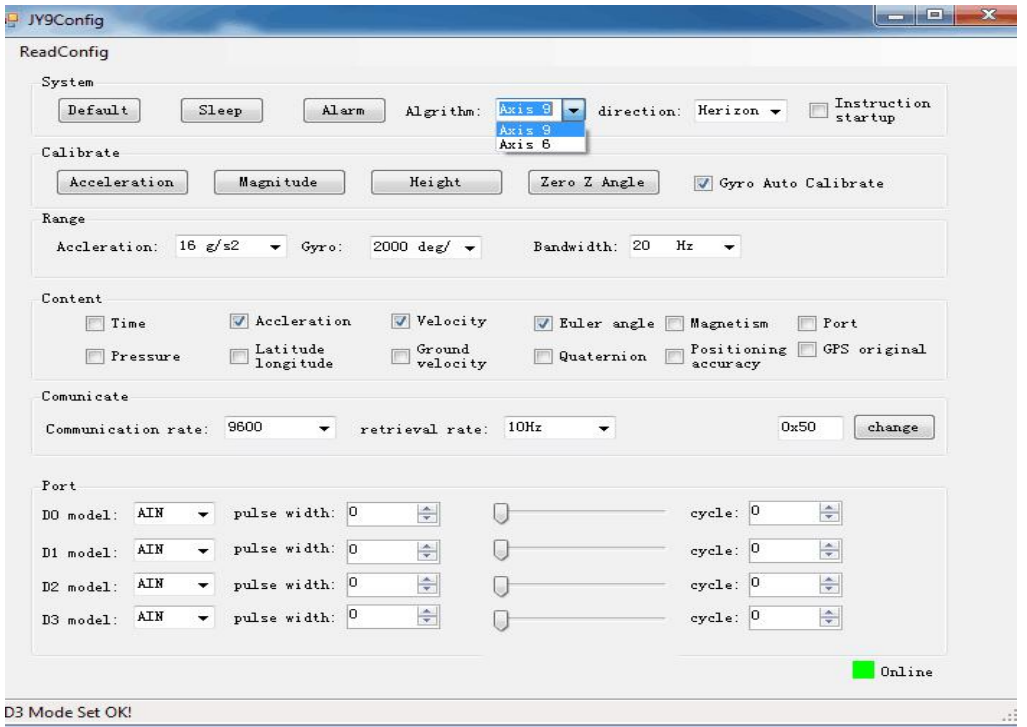
Reminder: here only JY901 can do the algorithm conversion, and the system defaults to the 9 axis algorithm. JY61P is unable to convert algorithms.
SD card storage data
Method of storing data
- Insert the SD card into the memory card slot on the back of the module to supply power to the module. After the module is powered on (1~2S), the module starts to work and stores data.
- The data is stored in the TXT file in hexadecimal output.

SD card data playback
- In this product, the SD card is mainly used to record data. The product will only transfer data when the SD card is inserted into the product.
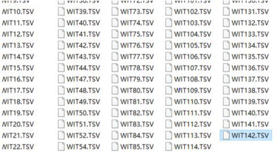
Each time the SD card is inserted, the data is recorded once. The data will be stored in the SD card as a text. The text number is the number of times the data was recorded. For example, the last file name at this time is WIT142.TSV. Insert the SD card once, remove the SD card for a period of time, and then use a card reader to read the SD card file. At this time, the last file name should be WIT143.TSV.
The SD card file is readable. On the host computer corresponding to the product, open the host computer and click File-Load-
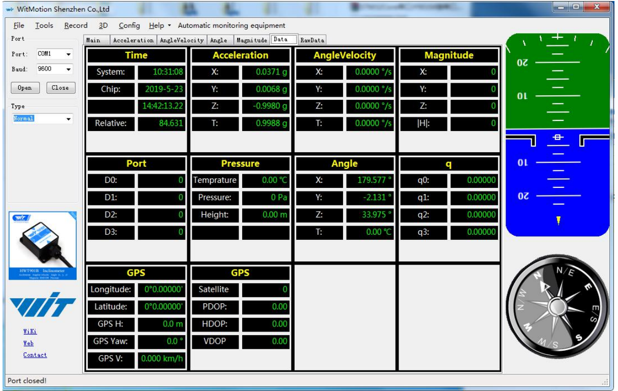
Select all files --- select the file to be read-run, you can read out the data in the file, which is represented by a graph in the upper computer.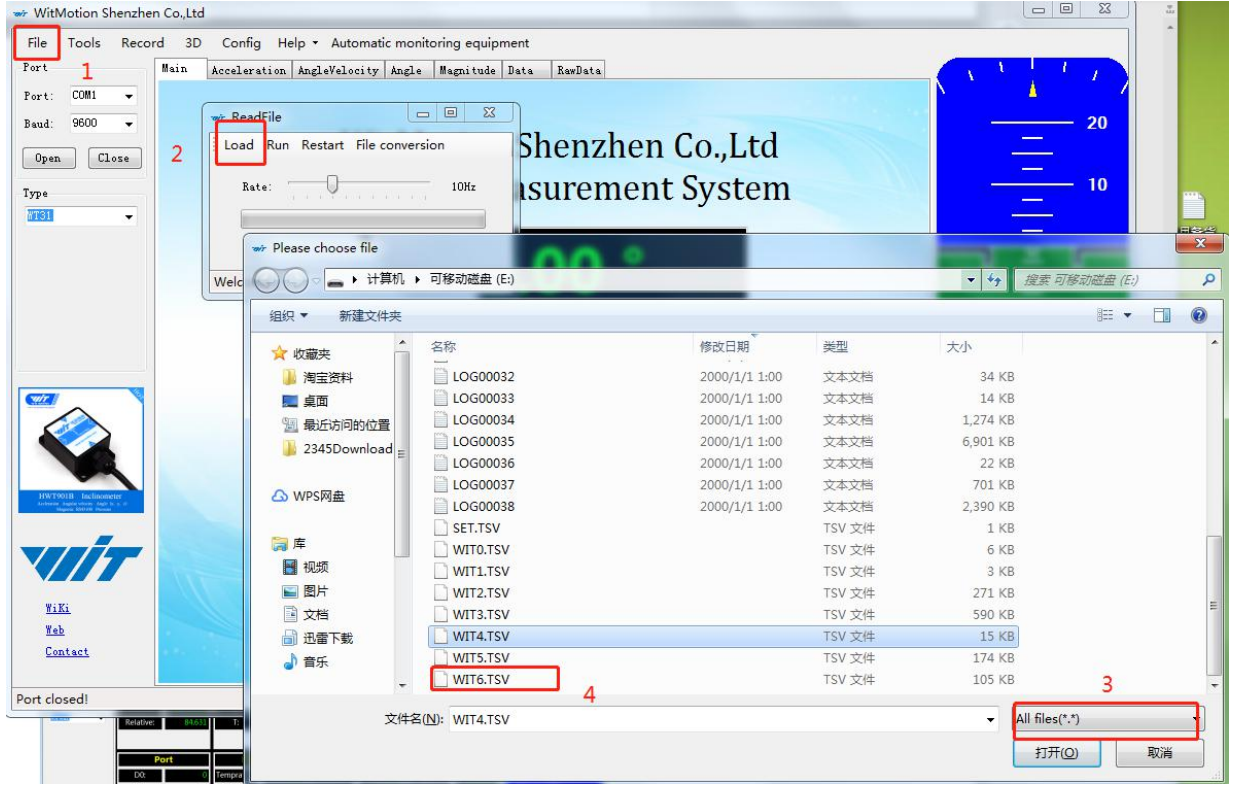
And you will get the data on PC software as below:
Text Conversion
Tutorial of converting SD card TSV file format data to TXT file format data tutorial:
After the data can be played back, click "File Conversion".
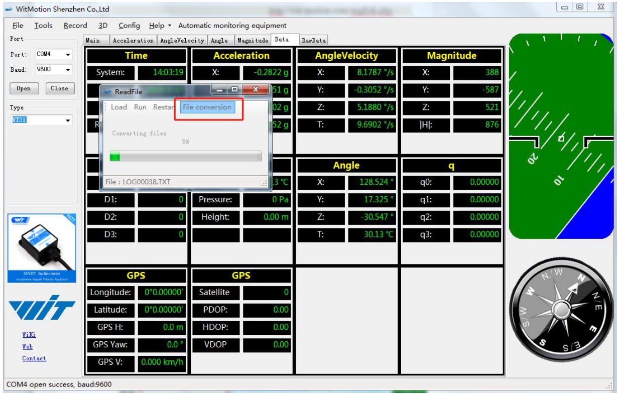
After the conversion reaches 100%, it will pop up whether to open the conversion document and the path of the conversion document.
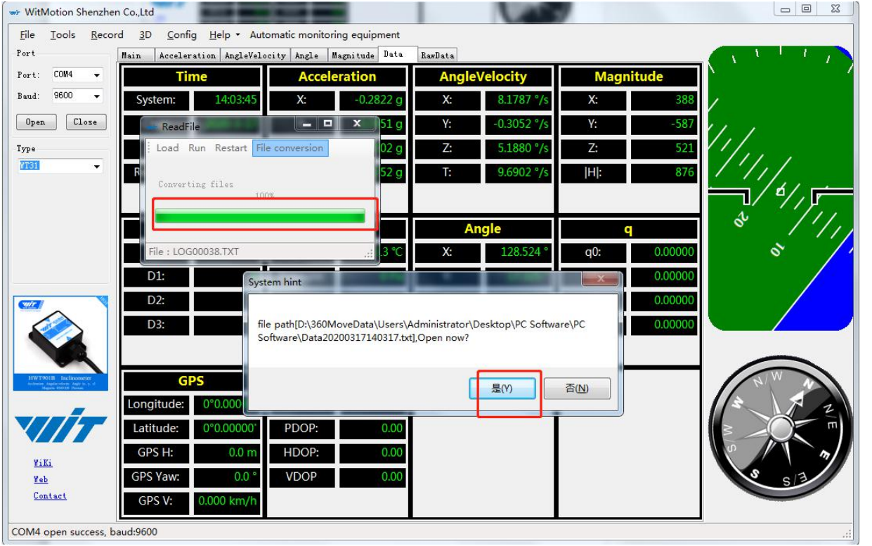
Click Yes to open the document as shown in the figure below, 1 represents the time to convert the document, 2 represents the time to convert the data, and 3 represents the time to record the data.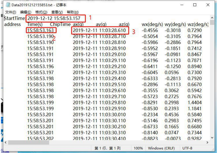
Setup Guide
To set up the Witmotion Angle Storage Sensor WT901SDCL, follow these steps:
- Hardware Assembly: Connect the sensor module to your system via the chosen communication interface (I2C, SPI, or UART). Ensure proper connection to a power source within the specified voltage range (3.3V to 5V).
- Software Configuration: Use the provided software library or SDK to configure the sensor settings. This includes setting the measurement range, data storage parameters, and communication protocol.
- Calibration: Perform an initial calibration if necessary to ensure accurate readings. This can be done using the manufacturer's calibration tool or by following the calibration procedure outlined in the user manual.
- Pairing: If integrating with other devices, ensure that the communication settings are compatible and correctly configured.
Troubleshooting
Here are some common issues and solutions when using the Witmotion Angle Storage Sensor WT901SDCL:
- Incorrect Readings: Check for proper calibration and ensure that the sensor is not exposed to external magnetic fields or vibrations.
- Data Loss: Verify that the storage capacity has not been exceeded and that the device is properly powered.
- Communication Errors: Ensure correct wiring and configuration of the communication interface. Refer to the user manual for troubleshooting steps specific to your setup.
Instructions & Warnings: Always follow proper handling procedures to avoid damaging the sensor. Ensure that the operating temperature is within the specified range to maintain accuracy and longevity of the device.
Witmotion Angle Storage Sensor WT901SDCL Pros & Cons
Pros
- High Accuracy: The WT901SDCL offers precise angular measurements with an accuracy of ±0.5 degrees.
- Multiple Interfaces: Supports I2C, SPI, and UART communication protocols for flexibility in integration.
- Data Storage: Capable of storing up to 10,000 data points internally, ideal for applications requiring offline data collection.
- Compact Design: Small form factor makes it easy to integrate into various projects.
Cons
- Cost: May be more expensive than some other angle measurement solutions on the market.
- Complexity: Requires some technical expertise for setup and configuration.
- Power Consumption: While low, it still requires a stable power source within a specific voltage range.
Customer Reviews
Customers have praised the Witmotion Angle Storage Sensor WT901SDCL for its high accuracy and reliability. Many users appreciate the ease of integration due to its multiple communication interfaces. However, some have noted that the setup process can be complex for beginners.
A common complaint is the relatively higher cost compared to other sensors, but most agree that the precision and features justify the price. Overall, the sensor has received positive feedback for its performance in various industrial and hobbyist projects.
Faqs
What is the measurement range of the Witmotion Angle?
How accurate is the Witmotion Angle Storage?
What communication interfaces does the Storage Sensor support?
What is the power supply requirement for the Witmotion Angle?
How much data can the WT901SDCL store internally?
Is the Witmotion Angle Storage Sensor WT901SDCL suitable for harsh environments?
How do I calibrate the Witmotion?
Why might I experience incorrect readings from the Witmotion Angle Storage Sensor WT901SDCL?
Can I use the Witmotion Angle Storage Sensor in robotic applications?
Is the Witmotion Angle compatible with Arduino?
Leave a Comment
