Asus Prime Motherboard Z590-A User Manual | Installation Instruction
Content
Introduction
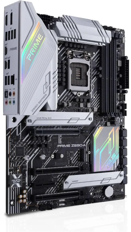
The Asus Prime Z590-A motherboard is a high-performance motherboard designed for Intel's 10th and 11th generation processors, utilizing the LGA 1200 socket. It supports a wide range of Intel CPUs, including the Intel Core i3, i5, i7, i9, as well as Celeron and Pentium G series, allowing for flexible system configurations tailored to various user needs.
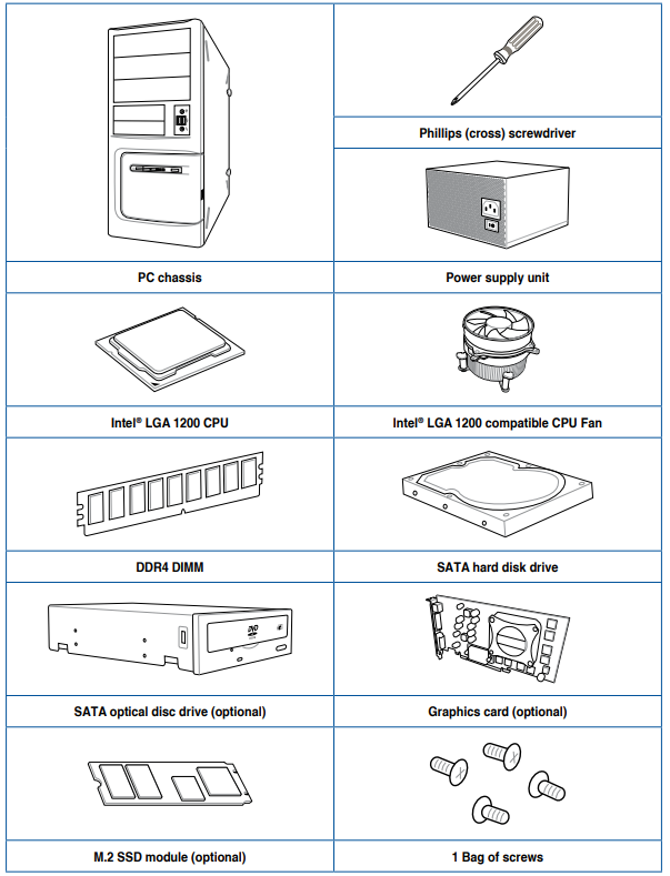
Installation Tools and Components
| Configuration | 1 | 2 |
|---|---|---|
| A | ||
| PCIEX16_1 | x16 | x8 |
| PCIEX16_2 | - | x4 |
| PCIEX16_3 | - | x4 |
| Configuration | 1 | 2 |
| B | ||
| M.2_2 | V (SATA mode) | V (PCIe mode) |
| SATA6G_2 | - | V |
| Configuration | 1 | 2 |
| C | ||
| M.2_3 | V (SATA mode) | V (PCIe mode) |
| SATA6G_6 | - | V |
The tools and components in the table above are not included in the motherboard package.
Package Contents
Check your motherboard package for the following items:
- Motherboard: 1 x PRIME Z590-A motherboard
- Cables: 3 x SATA 6Gb/s cables
- Miscellaneous: 2 x M.2 Rubber Packages, 1 x Q-connector
- Installation Media: 1 x Support DVD
- Documentation: 1 x User manual
If any of the above items is damaged or missing, contact your retailer.
PRIME Z590-A Specifications Summary
| Category | Details |
|---|---|
| CPU | Intel® Socket LGA1200 for 11th Gen Intel® Core™ processors & 10th Gen Intel® Core™, Pentium® Gold and Celeron® Processors. Supports Intel® 14 nm CPU. Supports Intel® Turbo Boost Technology 2.0 and Intel® Turbo Boost Max Technology 3.0. |
| * Refer to for CPU support list. | |
| ** Intel® Turbo Boost Max Technology 3.0 support depends on the CPU types. | |
| Chipset | Intel® Z590 Chipset |
| Memory | 4 x DIMM, Max. 128GB, DDR4 5133(OC) / 5000(OC) / 4800(OC) / 4700(OC) / 4600(OC) / 4500(OC) / 4400(OC) / 4266(OC) / 4133(OC) / 4000(OC) / 3866(OC) / 3733(OC) / 3600(OC) / 3466(OC) / 3400(OC) / 3333(OC) / 3200 / 3000 / 2933 / 2800 / 2666 / 2400 / 2133 MHz Non-ECC, Un-buffered Memory. |
| Dual Channel Memory Architecture. | |
| Supports Intel® Extreme Memory Profile (XMP). | |
| OptiMem II. | |
| * 10th Gen Intel® Core™ i7/i9 processors support 2933 / 2800 / 2666 / 2400 / 2133 natively, others will run at the maximum transfer rate of DDR4 2666MHz. | |
| * 11th Gen Intel® Core™ processors support 3200 / 2933 / 2800 / 2666 / 2400 / 2133 natively. | |
| * Refer to for the Memory QVL (Qualified Vendors Lists), and memory frequency support depends on the CPU types. | |
| Graphics | 1 x DisplayPort 1.4. |
| 1 x HDMI™ 2.0. | |
| * Graphics specifications may vary between CPU types. | |
| ** Only Intel® 11th Core™ processors support DisplayPort 1.4 with max. resolution of 5120 x 2880 @60Hz, others will only support DisplayPort 1.4 with max. resolution of 4096 x 2304 @60Hz. | |
| *** Only Intel® 11th Core™ processors, support HDMI™ 2.0 with max. resolution of 4K@60Hz, others would only support HDMI™ 1.4 with max. resolution of 4K@30Hz. | |
| **** VGA resolution support depends on processors’ or graphic cards’ resolution. | |
| Expansion Slots | Intel® 11th & 10th Gen Processors |
| 3 x PCIe 4.0/3.0 x16 slots. | |
| - Intel® 11th Core™ processors support PCIe 4.0 x16. | |
| - Intel® 10th processors support PCIe 3.0 x16. | |
| Intel® Z590 Chipset. | |
| 1 x PCIe 3.0 x4 slot. | |
| * Supports PCIe bandwidth bifurcation for RAID on CPU function. | |
| Storage | Total supports 3 x M.2 slots and 6 x SATA 6Gb/s ports. |
| Intel®11th Gen Processors. | |
| M.2_1 slot (Key M), type 2242/2260/2280/22110. | |
| - Only Intel® 11th Core™ processors support PCIe 4.0 x4 mode, this slot will be disabled for other CPUs. | |
| Intel® Z590 Chipset. | |
| M.2_2 slot (Key M), type 2242/2260/2280/22110 (supports PCIe 3.0 x4 & SATA modes). | |
| M.2_3 slot (Key M), type 2242/2260/2280/22110 (supports PCIe 3.0 x4 & SATA modes). | |
| 6 x SATA 6Gb/s ports. | |
| Raid function for PCIe mode SSD in Intel® Rapid Storage Technology is available with either 1. Intel® SSDs installed in both CPU-attached and PCH-attached slots, or 2. any other 3rd party SSDs installed in PCH-attached slots. | |
| To enable Intel® Optane™ Memory (Hybrid Storage device), it must be installed in PCH-attached slots with Intel® Rapid Storage Technology. | |
| * M.2_2 shares bandwidth with SATA6G_2. When M.2_2 runs SATA mode, SATA6G_2 will be disabled. | |
| ** M.2_3 shares bandwidth with SATA6G_6. When M.2_3 runs SATA mode, SATA6G_6 will be disabled. | |
| Ethernet | 1 x Intel® I225-V 2.5Gb Ethernet. |
| USB | Rear USB (Total 9 ports). |
| 1 x USB 3.2 Gen 2x2 port (1 x USB Type-C®). | |
| 4 x USB 3.2 Gen 2 ports (3 x Type-A, 1 x Type-C®). | |
| 4 x USB 2.0 ports (4 x Type-A). | |
| Front USB (Total 7 ports). | |
| 1 x USB 3.2 Gen 1 connector (supports USB Type-C®). | |
| 1 x USB 3.2 Gen 1 header supports additional 2 USB 3.2 Gen 1 ports. | |
| 2 x USB 2.0 headers support additional 4 USB 2.0 ports. | |
| Audio | Realtek S1220A 7.1 Surround Sound High Definition Audio CODEC. |
| - Impedance sense for front and rear headphone outputs. | |
| - Internal audio Amplifier to enhance the highest quality sound for headphone and speakers. | |
| - Supports: Jack-detection, Multi-streaming, Front Panel Jack-retasking. | |
| - High quality 120 dB SNR stereo playback output and 113 dB SNR recording input (Line-in). | |
| - Supports up to 32-Bit/192 kHz playback. | |
| Audio Features: | |
| - Power pre-regulator reduces power input noise to ensure consistent performance. | |
| - Rear optical S/PDIF out port. | |
| - Premium Japanese audio capacitors. | |
| - Audio Shielding. | |
| - Dedicated audio PCB layers. | |
| - Audio cover. | |
| - Unique de-pop circuit. | |
| * Due to limitations in HDA bandwidth, 32-Bit/192kHz is not supported for 7.1-Channel audio. | |
| Back Panel I/O Ports | 1 x USB 3.2 Gen 2x2 port (1 x USB Type-C®). |
| 4 x USB 3.2 Gen 2 ports (3 x Type-A, 1 x Type-C®). | |
| 4 x USB 2.0 ports (4 x Type-A). | |
| 1 x DisplayPort. | |
| 1 x HDMI™ port. | |
| 1 x Intel® I225-V 2.5Gb Ethernet port. | |
| 5 x Audio jacks. | |
| 1 x Optical S/PDIF out port. | |
| Internal I/O connectors | Fan and cooling related. |
| 1 x 4-pin CPU Fan header. | |
| 1 x 4-pin CPU OPT Fan header. | |
| 1 x 4-pin AIO Pump header. | |
| 3 x 4-pin Chassis Fan headers. | |
| 1 x 4-pin VRM_HS Fan header. | |
| 1 x W_PUMP+ header. | |
| Power related. | |
| 1 x 24-pin Main Power connector. | |
| 1 x 8-pin +12V Power connector. | |
| 1 x 4-pin +12V Power connector. | |
| Storage related. | |
| 3 x M.2 slots (Key M). | |
| 6 x SATA 6Gb/s ports. | |
| USB. | |
| 1 x USB 3.2 Gen 1 connector (supports USB Type-C®). | |
| 1 x USB 3.2 Gen 1 headers supports additional 2 USB 3.2 Gen 1 ports. | |
| 2 x USB 2.0 headers support additional 4 USB 2.0 ports. | |
| Miscellaneous. | |
| 3 x AURA Addressable Gen 2 headers. | |
| 1 x AURA RGB headers. | |
| 1 x Clear CMOS header. | |
| 1 x COM Port header. | |
| 1 x Front Panel Audio header (AAFP). | |
| 1 x CPU Over Voltage jumper. | |
| 1 x Power button. | |
| 1 x SPI TPM header (14-1pin). | |
| 1 x 20-3 pin System Panel header with Chassis intrude function. | |
| 1 x Thermal Sensor header. | |
| 1 x Thunderbolt™ header. | |
| Special Features | ASUS 5X PROTECTION III. |
| - ASUS DIGI+ VRM (- Digital power design with Dr. MOS). | |
| - ASUS Enhanced DRAM Overcurrent Protection. | |
| - ASUS ESD Guards. | |
| - ASUS LANGuard. | |
| - ASUS Overvoltage Protection. | |
| - ASUS Stainless-Steel Back I/O. | |
| ASUS Q-Design: | |
| - M.2 Q-Latch. | |
| - ASUS Q-Connector. | |
| - ASUS Q-DIMM. | |
| - ASUS Q-LED (CPU [red], DRAM [yellow], VGA [white], Boot Device [yellow-green]). | |
| - ASUS Q-Slot. | |
| ASUS Thermal Solution: | |
| - Aluminum M.2 Heatsink. | |
| - Flexible M.2 heatsink. | |
| ASUS EZ DIY: | |
| - Procool. | |
| - Pre-mounted I/O shield. | |
| - ASUS SafeSlot. | |
| Software Features | ASUS Exclusive Software: |
| Armoury Crate: | |
| - Aura Creator. | |
| - Aura Sync. | |
| - Two-Way AI Noise Cancelation. | |
| AI Suite 3: | |
| - 5-Way Optimization with AI Overclocking. | |
| TPU. | |
| EPU. | |
| Digi+ VRM. | |
| Fan Xpert 4. | |
| Turbo app. | |
| - EZ update. | |
| AI Charger. | |
| ASUS CPU-Z. | |
| ASUS Turbo LAN. | |
| MyAsus. | |
| DTS® Ultra. | |
| UEFI BIOS. | |
| AI Overclocking Guide. | |
| ASUS EZ DIY: | |
| - ASUS CrashFree BIOS 3. | |
| - ASUS EZ Flash 3. | |
| - ASUS UEFI BIOS EZ Mode. | |
| - EZ Tuning Wizard. | |
| FlexKey. | |
| BIOS | 256 Mb Flash ROM, UEFI AMI BIOS |
| Manageability | WOL by PME, PXE |
| Operating System | Windows® 10 - 64 bit |
| Form Factor | ATX Form Factor. 12 inch x 9.6 inch (30.5 cm x 24.4 cm) |
- Specifications are subject to change without notice. Please refer to the ASUS website for the latest specifications.
- MyASUS offers a variety of support features such as helping to troubleshoot issues, optimizing product performance, integrating ASUS software, and recovery drive creation. Please scan the QR Code for installation guide and FAQ.
Connectors with Shared Bandwidth
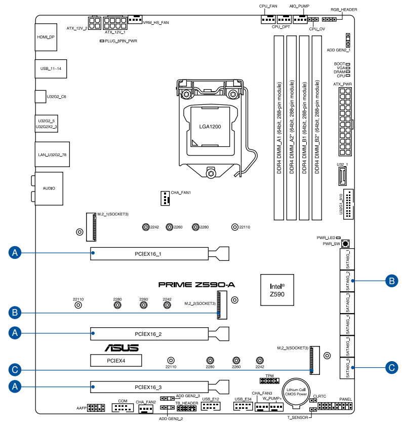
- M.2_2 shares bandwidth with SATA6G_2. When M.2_2 runs SATA mode, SATA6G_2 will be disabled.
- M.2_3 shares bandwidth with SATA6G_6. When M.2_3 runs SATA mode, SATA6G_6 will be disabled.
Description
The Asus Prime Motherboard Z590-A is a high-performance motherboard that supports the latest Intel 11th Gen processors. It has a robust power delivery system and advanced cooling options to ensure stable performance even under heavy loads. The motherboard features extensive connectivity options, including USB 3.2 Gen 2x2 Type-C, Thunderbolt 4, and 2.5 Gb Ethernet. The Z590-A also features AI overclocking and cooling features to optimize performance and stability. The motherboard has a sleek and modern design with RGB lighting and Aura Sync technology for customizable lighting effects.
Before You Proceed
Take note of the following precautions before you install motherboard components or change any motherboard settings:
- Unplug the power cord from the wall socket before touching any component.
- Before handling components, use a grounded wrist strap or touch a safely grounded object or a metal object, such as the power supply case, to avoid damaging them due to static electricity.
- Hold components by the edges to avoid touching the ICs on them.
- Whenever you uninstall any component, place it on a grounded antistatic pad or in the bag that came with the component.
- Before you install or remove any component, ensure that the ATX power supply is switched off or the power cord is detached from the power supply. Failure to do so may cause severe damage to the motherboard, peripherals, or components.
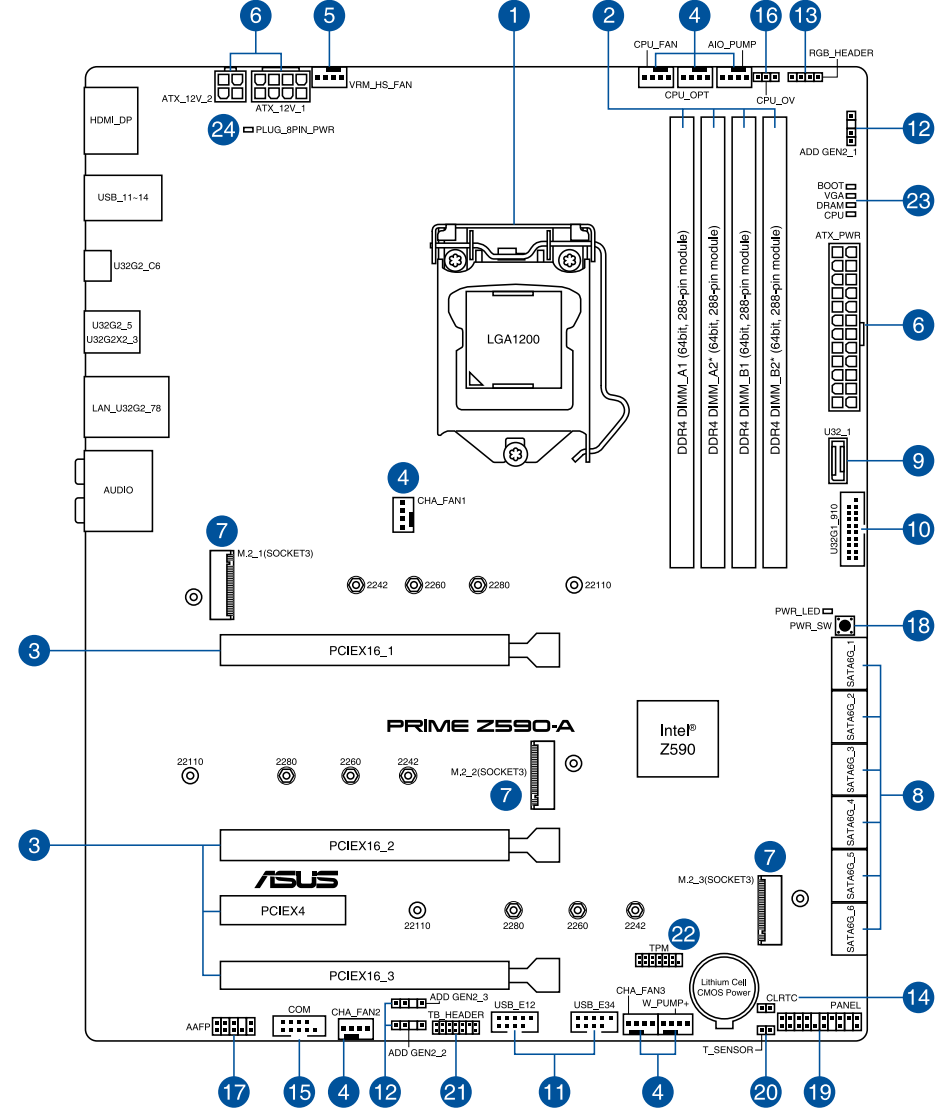
Motherboard Layout
| Layout Contents |
|---|
| 1. CPU socket |
| 2. DIMM slots |
| 3. Expansion slots |
| 4. Fan and Pump headers |
| 5. VRM Heatsink Fan header |
| 6. Power connectors |
| 7. M.2 Slot |
| 8. SATA 6GB/s port |
| 9. USB 3.2 Gen 1 Type-C® Front Panel connector |
| 10. USB 3.2 Gen 1 header |
| 11. USB 2.0 header |
| 12. AURA Addressable Gen 2 header |
| 13. AURA RGB header |
| 14. Clear RTC RAM jumper |
| 15. COM Port connector |
| 16. CPU Over Voltage jumper |
| 17. Front Panel Audio header |
| 18. Power button |
| 19. System Panel header |
| 20. Thermal Sensor header |
| 21. Thunderbolt™ header |
| 22. TPM header |
| 23. Q-LEDs |
| 24. 8-pin Power Plug LED |
CPU Socket
The motherboard comes with an LGA1200 socket designed for 11th Gen Intel Core processors & 10th Gen Intel Core, Pentium Gold, and Celeron Processors.
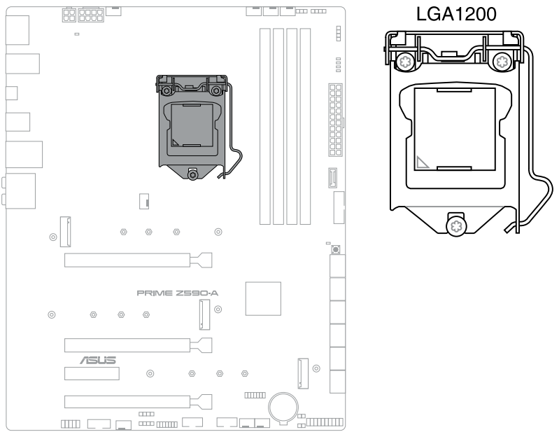
- Ensure that you install the correct CPU designed for the LGA1200 socket only. DO NOT install a CPU designed for other sockets on the LGA1200 socket.
- The CPU fits in only one correct orientation. DO NOT force the CPU into the socket to prevent bending the connectors on the socket and damaging the CPU.
- Ensure that all power cables are unplugged before installing the CPU.
- Upon purchase of the motherboard, ensure that the PnP cap is on the socket and the socket contacts are not bent. Contact your retailer immediately if the PnP cap is missing, or if you see any damage to the PnP cap/socket contacts/motherboard components. ASUS will shoulder the cost of repair only if the damage is shipment/transit-related.
- Keep the cap after installing the motherboard. ASUS will process Return Merchandise Authorization (RMA) requests only if the motherboard comes with the cap on the LGA1200 socket.
- The product warranty does not cover damage to the socket contacts resulting from incorrect CPU installation/removal, or misplacement/loss/incorrect removal of the PnP cap.
DIMM Slots
The motherboard comes with Dual Inline Memory Modules (DIMM) slots designed for DDR4 (Double Data Rate 4) memory modules.
- A DDR4 memory module is notched differently from a DDR, DDR2, or DDR3 module. DO NOT install a DDR, DDR2, or DDR3 memory module to the DDR4 slot.

Recommended Memory Configurations
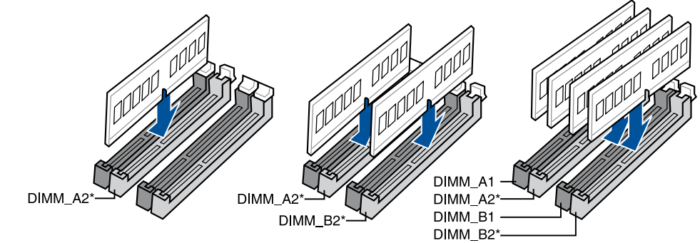
Memory configurations
You may install 4 GB, 8 GB, 16 GB, and 32 GB unbuffered and non-ECC DDR4 DIMMs into the DIMM sockets.
- You may install varying memory sizes in Channel A and Channel B. The system maps the total size of the lower-sized channel for the dual-channel configuration. Any excess memory from the higher-sized channel is then mapped for single-channel operation.
- The default memory operation frequency is dependent on its Serial Presence Detect (SPD), which is the standard way of accessing information from a memory module. Under the default state, some memory modules for overclocking may operate at a lower frequency than the vendor-marked value.
- For system stability, use a more efficient memory cooling system to support a full memory load or overclocking condition.
- Always install the DIMMS with the same CAS Latency. For optimum compatibility, we recommend that you install memory modules of the same version or data code (D/C) from the same vendor. Check with the vendor to get the correct memory modules.
- Visit the ASUS website for the latest QVL.
Expansion Slots
Unplug the power cord before adding or removing expansion cards. Failure to do so may cause you physical injury and damage motherboard components.
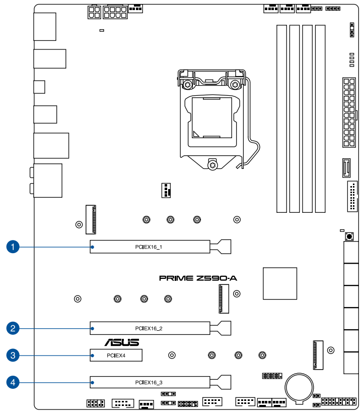
Recommended VGA Configuration
| Slot Description | Single VGA | Dual VGA | Triple VGA |
|---|---|---|---|
| PCIe 4.0/3.0 x16_1 | x16 | x8 | x8 |
| PCIe 4.0/3.0 x16_2 | - | x4 | x4 |
| PCIe 3.0 x4 | - | - | - |
| PCIe 4.0/3.0 x16_3 | - | - | x4 |
Connect a chassis fan to the chassis fan connectors when using multiple graphics cards for better thermal environment.
PCIe Bifurcation & M.2 Settings in PCIe x16 Slots (from CPU)
| Slot Description | Quantity of Identifiable Intel M.2 SSD (pcs) |
|---|---|
| Situation 1 (x8+x4+x4) | Situation 2 (x8) |
| PCIe 4.0/3.0 x16_1 | 3 |
| PCIe 4.0/3.0 x16_2 | 0 |
| PCIe 4.0/3.0 x16_3 | 0 |
| M.2_1 | 1 |
- Hyper M.2 X16 series card sold separately.
- M.2_1 is only supported with Intel 11th Core processors.
- Enable the Hyper M.2 X16 series card under BIOS settings.
Fan and Pump Headers
The Fan and Pump headers allow you to connect fans or pumps to cool the system.
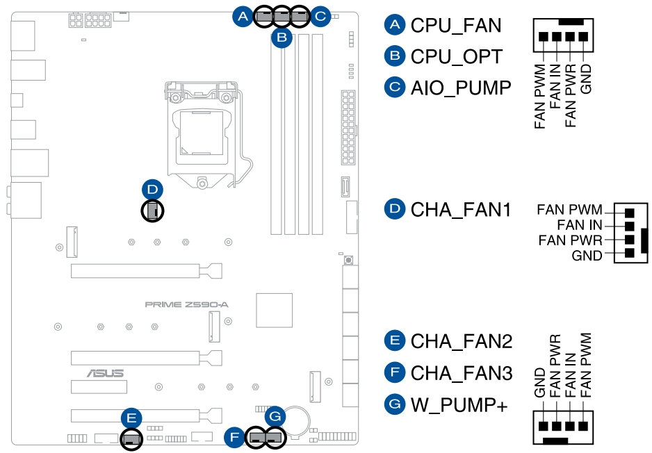
- DO NOT forget to connect the fan cables to the fan headers. Insufficient airflow inside the system may damage the motherboard components. These are not jumpers! Do not place jumper caps on the fan headers!
- Ensure the cable is fully inserted into the header.
- For water cooling kits, connect the pump connector to the W_PUMP+ header.
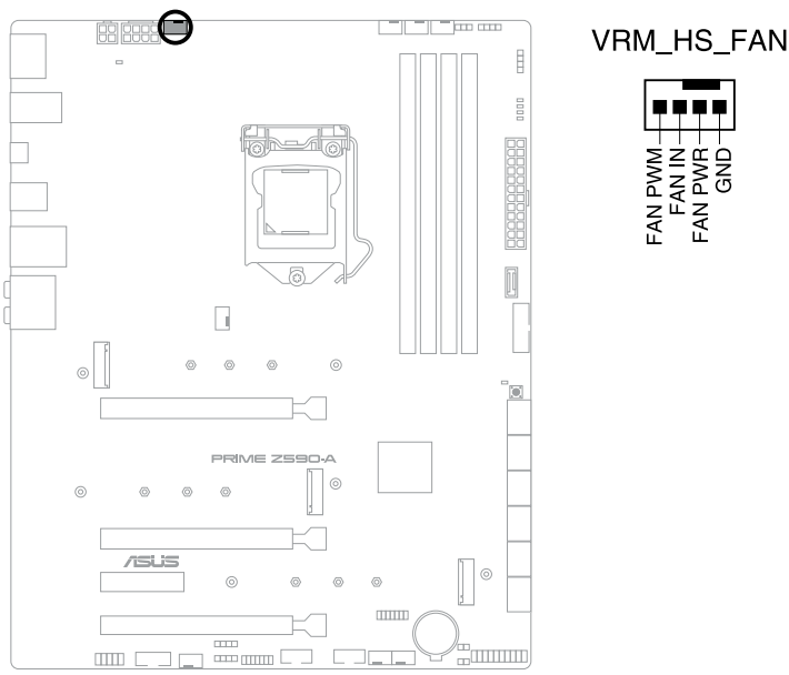
VRM Heatsink Fan Header
The VRM Heatsink fan header is for connecting the VRM Heatsink fan on the integrated heatsink, and can also be used as a chassis fan header.
| Header | Max. Current | Max. Power | Default Speed | Shared Control |
|---|---|---|---|---|
| CPU_FAN | 1A | 12W | Q-Fan Controlled | - |
| CPU_OPT | 1A | 12W | Q-Fan Controlled | - |
| CHA_FAN1 | 1A | 12W | Q-Fan Controlled | - |
| CHA_FAN2 | 1A | 12W | Q-Fan Controlled | - |
| CHA_FAN3 | 1A | 12W | Q-Fan Controlled | - |
| AIO_PUMP | 1A | 12W | Full Speed | - |
| W_PUMP+_1 | 3A | 36W | Full Speed | - |
| VRM_HS_FAN | 1A | 12W | Q-Fan Controlled | - |
Power Connectors
These Power connectors allow you to connect your motherboard to a power supply. The power supply plugs are designed to fit in only one orientation, find the proper orientation and push down firmly until the power supply plugs are fully inserted.
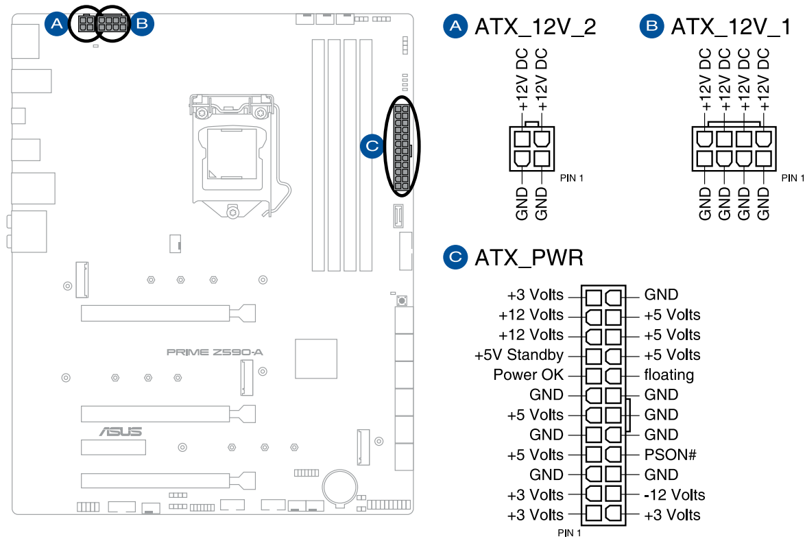
- Ensure to connect the 8-pin power plug.
- For a fully configured system, we recommend that you use a power supply unit (PSU) that complies with ATX 12V Specification 2.0 (or later version) and provides a minimum power of 350 W.
- We recommend that you use a PSU with a higher power output when configuring a system with more power-consuming devices. The system may become unstable or may not boot up if the power is inadequate.
- If you want to use two or more high-end PCI Express x16 cards, use a PSU with 1000W power or above to ensure system stability.
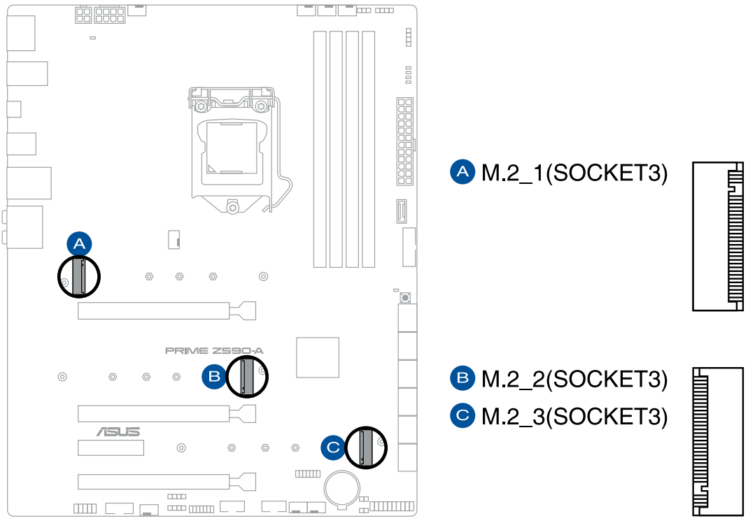
M.2 Slot
The M.2 slot allows you to install M.2 SSD modules.
- Intel 11th Core i5/i7/i9 Processors:
- M.2_1 supports PCIe 4.0 x4 mode M Key design and type 2242 / 2260 / 2280 / 22110 storage devices.
- M.2_2 supports PCIe 3.0 x4 and SATA mode M Key design and type 2242 / 2260 / 2280 / 22110 storage devices.
- M.2_3 supports PCIe 3.0 x4 and SATA mode M Key design and type 2242 / 2260 / 2280 / 22110 storage devices.
- M.2_2 shares bandwidth with SATA6G_2. When M.2_2 runs SATA mode, SATA6G_2 will be disabled.
- M.2_3 shares bandwidth with SATA6G_6. When M.2_3 runs SATA mode, SATA6G_6 will be disabled.
- RAID function in Intel Rapid Storage Technology is available with either Intel SSDs installed in both CPU-attached and PCH-attached slots, or any other 3rd party SSDs installed in PCH-attached slots.
- To enable Intel Optane Memory (Hybrid Storage device), it must be installed in PCH-attached slots with Intel Rapid Storage Technology.
- The M.2 SSD module is purchased separately.
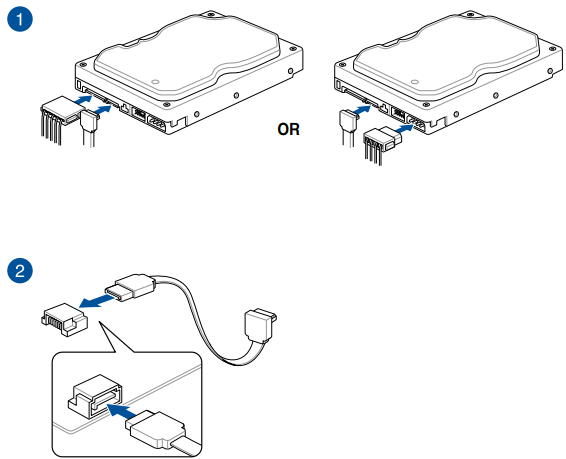
SATA 6Gb/s Ports
The SATA 6Gb/s ports allow you to connect SATA devices such as optical disc drives and hard disk drives via a SATA cable.
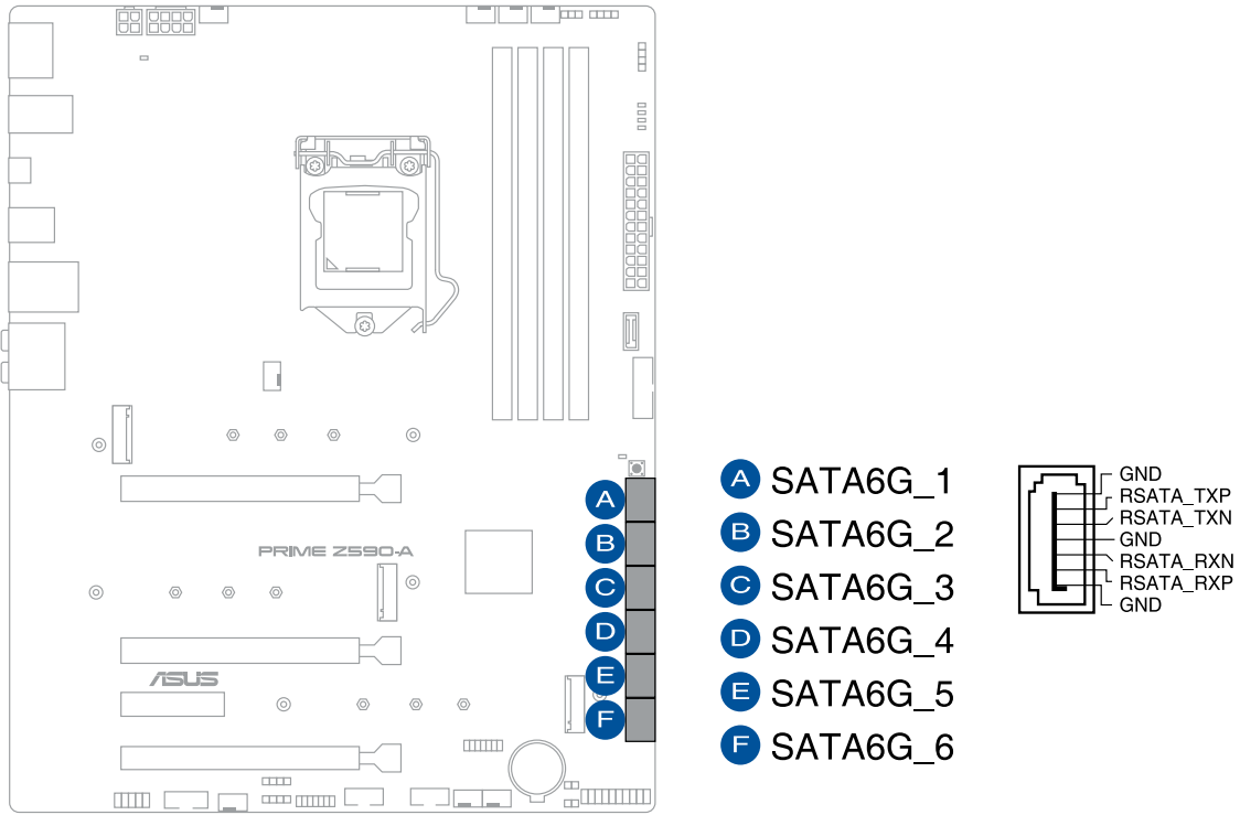
- If you installed SATA storage devices, you can create a RAID 0, 1, 5, and 10 configuration with the Intel Rapid Storage Technology through the onboard Intel Z590 chipset.
- The slots are set to [AHCI Mode] by default. If you intend to create a SATA RAID set using these connectors, set the SATA Mode item in the BIOS to [Intel RST Premium with Intel Optane System Acceleration (RAID)].
- M.2_2 shares bandwidth with SATA6G_2. When M.2_2 runs SATA mode, SATA6G_2 will be disabled.
- M.2_3 shares bandwidth with SATA6G_6. When M.2_3 runs SATA mode, SATA6G_6 will be disabled.
- Before creating a RAID set, refer to the RAID Configuration Guide. You can download the RAID Configuration Guide from the ASUS website.
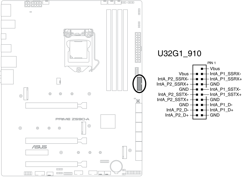
USB 3.2 Gen 1 Type-C Front Panel Connector
The USB 3.2 Gen 1 Type-C connector allows you to connect a USB 3.2 Gen 1 Type-C module for additional USB 3.2 Gen 1 ports in the front panel. The USB 3.2 Gen 1 Type-C connector provides data transfer speeds of up to 5 Gb/s.

- The USB 3.2 Gen 1 Type-C module is purchased separately.
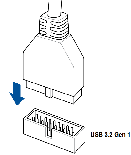
USB 3.2 Gen 1 Header
The USB 3.2 Gen 1 header allows you to connect a USB 3.2 Gen 1 module for additional USB 3.2 Gen 1 ports. The USB 3.2 Gen 1 header provides data transfer speeds of up to 5 Gb/s.
- The USB 3.2 Gen 1 module is purchased separately.
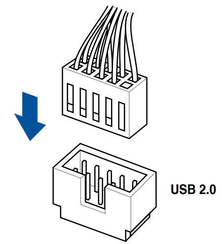
USB 2.0 Header
The USB 2.0 header allows you to connect a USB module for additional USB 2.0 ports. The USB 2.0 header provides data transfer speeds of up to 480 Mb/s connection speed.
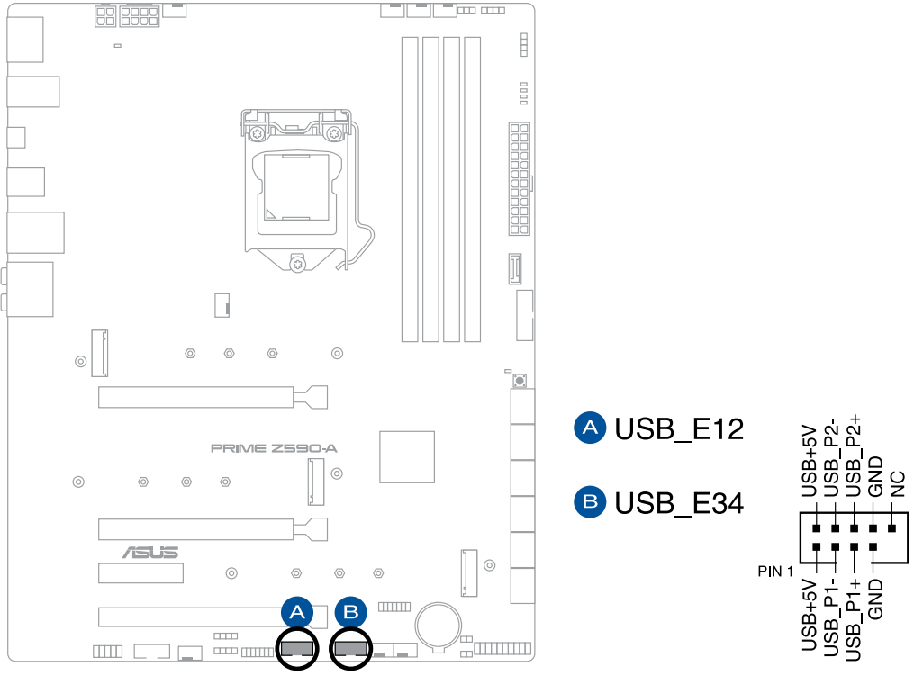
- DO NOT connect a 1394 cable to the USB connectors. Doing so will damage the motherboard!
- The USB 2.0 module is purchased separately.
AURA Addressable Gen2 Header
The Addressable Gen2 header allows you to connect individually addressable RGB WS2812B LED strips or WS2812B-based LED strips.
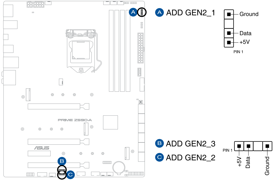
- The Addressable Gen2 header supports WS2812B addressable RGB LED strips (5V/Data/Ground), with a maximum power rating of 3A (5V), and the addressable headers on this board can handle a combined maximum of 500 LEDs.
- Before you install or remove any component, ensure that the power supply is switched off or the power cord is detached from the power supply. Failure to do so may cause severe damage to the motherboard, peripherals, or components.
- Actual lighting and color will vary with LED strip.
- If your LED strip does not light up, check if the addressable RGB LED strip is connected in the correct orientation, and if the 5V connector is aligned with the 5V header on the motherboard.
- The addressable RGB LED strip will only light up when the system is powered on.
- The addressable RGB LED strip is purchased separately.
AURA RGB Header
The AURA RGB header allows you to connect RGB LED strips.

- The AURA RGB header supports 5050 RGB multi-color LED strips (12V/G/R/B), with a maximum power rating of 3A (12V).
- Before you install or remove any component, ensure that the power supply is switched off or the power cord is detached from the power supply. Failure to do so may cause severe damage to the motherboard, peripherals, or components.
- Actual lighting and color will vary with LED strip.
- If your LED strip does not light up, check if the RGB LED extension cable and the RGB LED strip is connected in the correct orientation, and the 12V connector is aligned with the 12V header on the motherboard.
- The LED strip will only light up when the system is powered on.
- The LED strip is purchased separately.
Clear CMOS Header
The Clear CMOS header allows you to clear the Real Time Clock (RTC) RAM in the CMOS, which contains the date, time, system passwords, and system setup parameters.
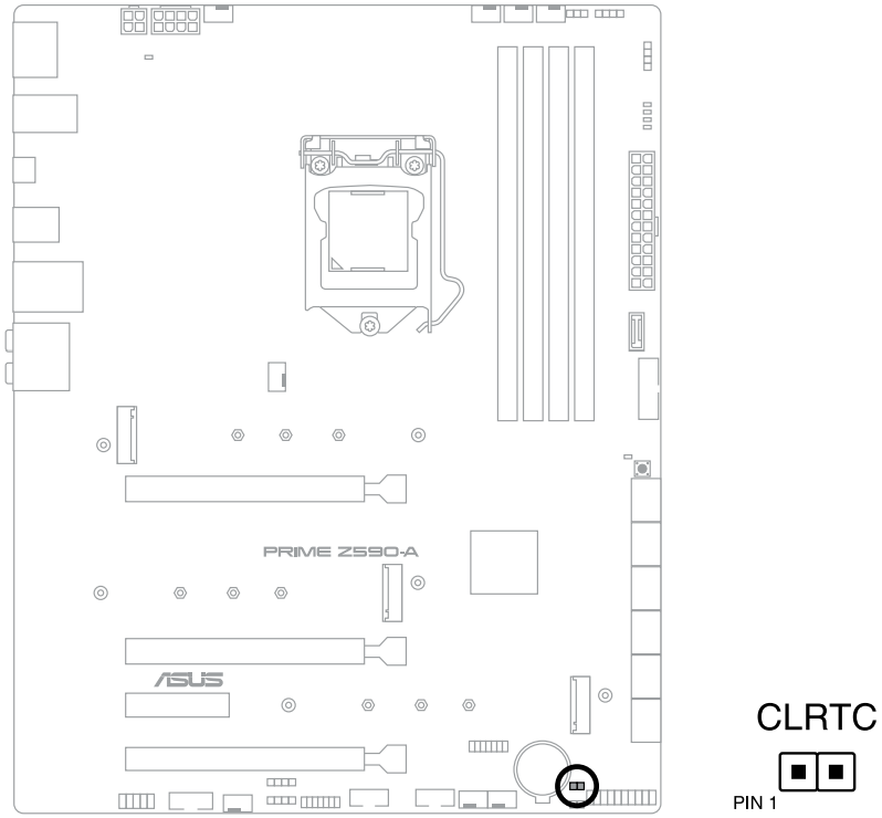
To erase the RTC RAM:
- Turn OFF the computer and unplug the power cord.
- Short-circuit pin 1-2 with a metal object or jumper cap for about 5-10 seconds.
- Plug the power cord and turn ON the computer.
- Hold down the <Del> key during the boot process and enter BIOS setup to re-enter data.
- DO NOT short-circuit the pins except when clearing the RTC RAM. Short-circuiting or placing a jumper cap will cause system boot failure!
- If the steps above do not help, remove the onboard button cell battery and move the jumper again to clear the CMOS RTC RAM data. After clearing the CMOS, reinstall the button cell battery.
COM Port Connector
The COM (Serial) Port connector allows you to connect a COM port module. Connect the COM port module cable to this connector, then install the module to a slot opening on the system chassis.
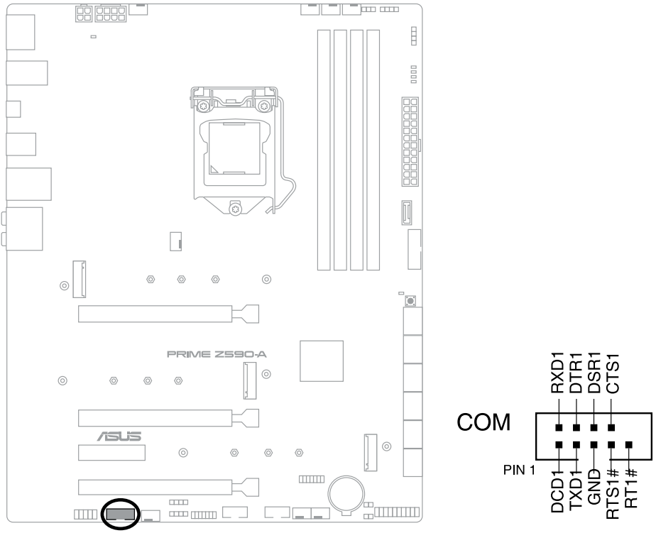
- The COM port module is purchased separately.
CPU Over Voltage Jumper
The CPU Over Voltage jumper allows you to set a higher CPU voltage for a flexible overclocking system (depending on the type of the installed CPU). Set to pins 2-3 to increase the CPU voltage setting, or set to pins 1-2 to use the default CPU voltage setting.

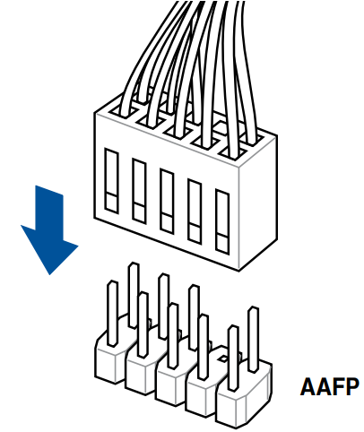
Front Panel Audio Header
The front panel audio header is for a chassis-mounted front panel audio I/O module that supports HD Audio. Connect one end of the front panel audio I/O module cable to this header.
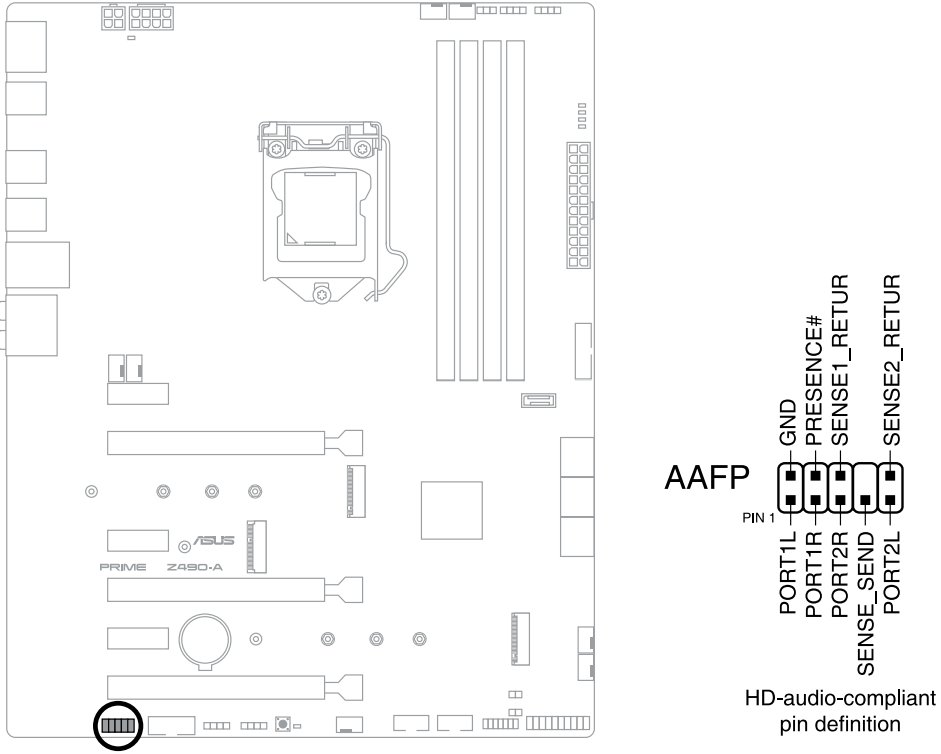
- We recommend that you connect a high-definition front panel audio module to this connector to avail of the motherboard’s high-definition audio capability.
Power Button
Press the Power button to power up the system, or put the system into sleep or soft-off mode (depending on the operating system settings).
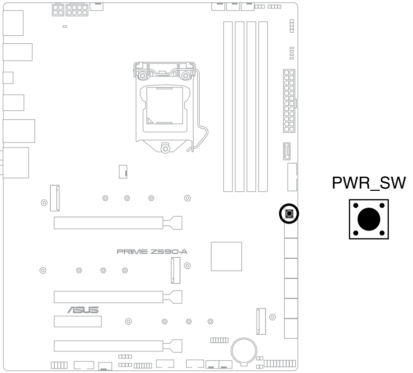
- The LED near the button also lights up when the system is plugged to a power source, indicating that you should shut down the system and unplug the power cable before removing or installing any motherboard component.
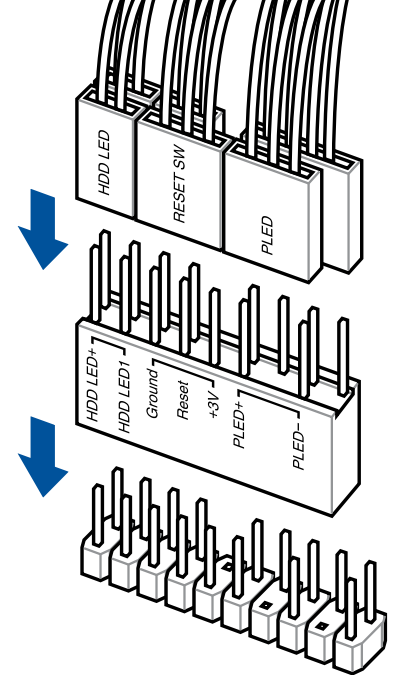
System Panel Header
The System Panel header supports several chassis-mounted functions.
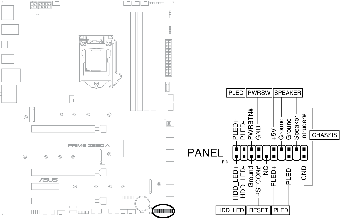
- System Power LED Header (PLED)
- The 2-pin header allows you to connect the System Power LED. The System Power LED lights up when the system is connected to a power source, or when you turn on the system power, and blinks when the system is in sleep mode.
- Storage Device Activity LED Header (HDD_LED)
- The 2-pin header allows you to connect the Storage Device Activity LED. The Storage Device Activity LED lights up or blinks when data is read from or written to the storage device or storage device add-on card.
- System Warning Speaker Header (SPEAKER)
- The 4-pin header allows you to connect the chassis-mounted system warning speaker. The speaker allows you to hear system beeps and warnings.
- Power Button/Soft-off Button Header (PWRSW)
- The 3-1 pin header allows you to connect the system power button. Press the power button to power up the system, or put the system into sleep or soft-off mode (depending on the operating system settings).
- Reset Button Header (RESET)
- The 2-pin header allows you to connect the chassis-mounted reset button. Press the reset button to reboot the system.
- Chassis Intrusion Connector (CHASSIS)
- The 2-pin connector allows you to connect the chassis-mounted intrusion detection sensor or switch. The chassis intrusion sensor or switch sends a high-level signal to the connector when a chassis component is removed or replaced, the signal is then generated as a chassis intrusion event.
Thermal Sensor Header
The Thermal Sensor header allows you to connect a sensor to monitor the temperature of the devices and the critical components inside the motherboard. Connect the thermal sensor and place it on the device or the motherboard’s component to detect its temperature.
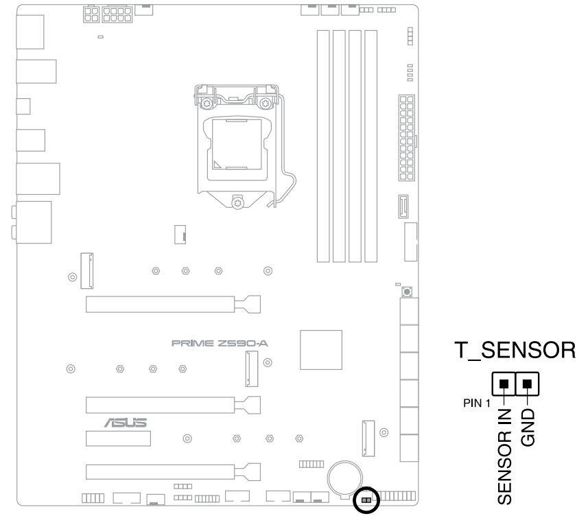
- The thermal sensor is purchased separately.
Thunderbolt Header
The Thunderbolt header allows you to connect an add-on Thunderbolt I/O card that supports Intel’s Thunderbolt Technology, allowing you to connect Thunderbolt-enabled devices to form a daisy-chain configuration.

- The add-on Thunderbolt I/O card and Thunderbolt cables are purchased separately.
- Please visit the official website of your purchased Thunderbolt card for more details on compatibility.
TPM Header
The TPM header allows you to connect a TPM module, which securely stores keys, digital certificates, passwords, and data. A TPM system also helps enhance network security, protect digital identities, and ensures platform integrity.
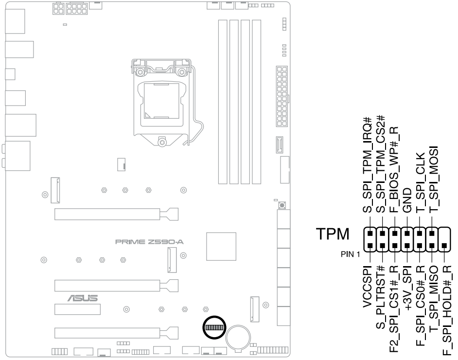
- The TPM module is purchased separately.
Q-LEDs
The Q-LEDs check key components (CPU, DRAM, VGA, and booting devices) during the motherboard booting process. If an error is found, the critical component’s LED stays lit up until the problem is solved.
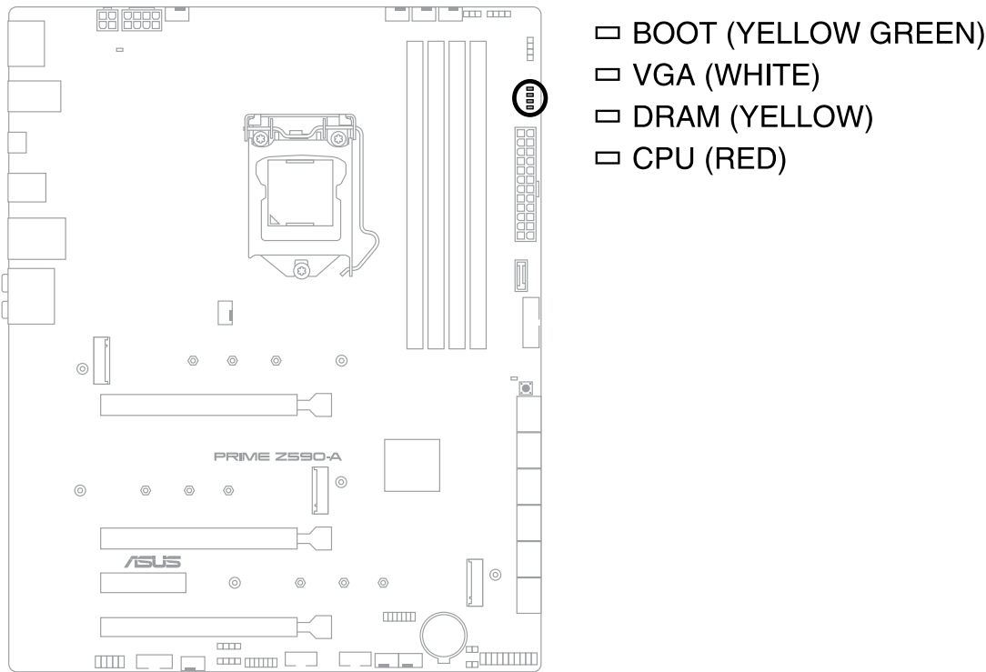
- The Q-LEDs provide the most probable cause of an error code as a starting point for troubleshooting. The actual cause may vary from case to case.
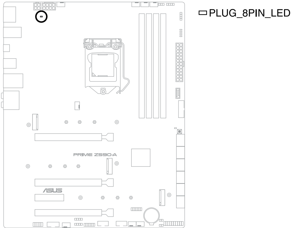
8-pin Power Plug LED
The 8-pin Power Plug LED lights up to indicate that the 8-pin power plug is not connected.
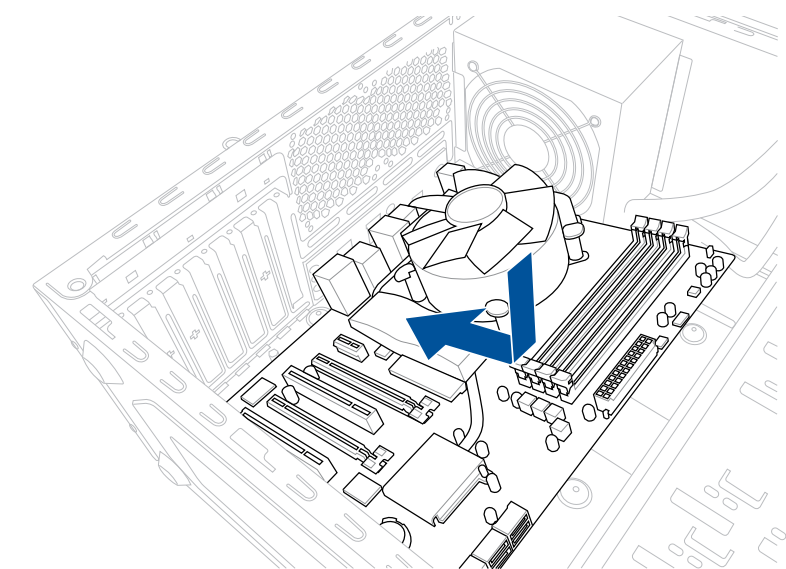
Motherboard Installation
Place the motherboard into the chassis, ensuring that its rear I/O ports are aligned to the chassis’ rear I/O panel.
Place nine (9) screws into the holes indicated by circles to secure the motherboard to the chassis.
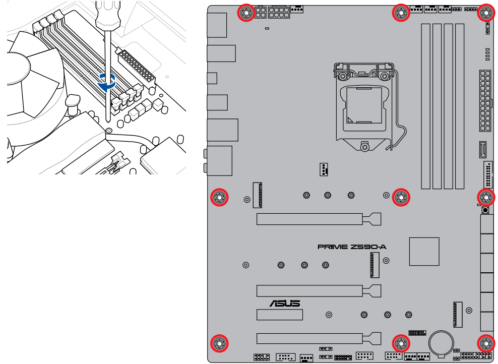
DO NOT over-tighten the screws! Doing so can damage the motherboard.
ATX Power Connection
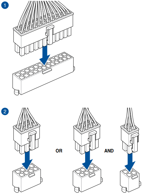
Ensure to connect the 8-pin power plug.
SATA Device Connection
Front I/O Connector
To Install ASUS Q-Connector
To Install a USB 3.2 Gen 1 Connector
To Install the Front Panel Audio Connector
To Install USB 3.2 Gen 1 Type-C Connector
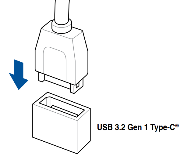
- This connector will only fit in one orientation. Push the connector until it clicks into place.
To Install USB 2.0 Connector
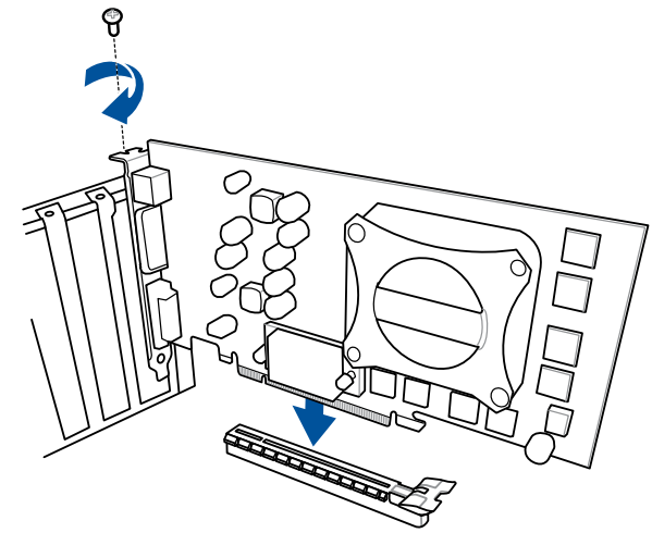
Expansion Card Installation
To Install PCIe x16 Cards
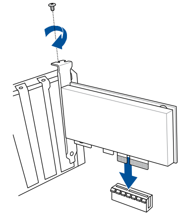
To Install PCIe x4 Cards
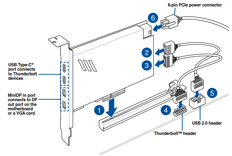
- To Install Thunderbolt Series Card
- Ensure to install the Thunderbolt series card to a PCIe slot from PCH.
- Step 6 is optional, please connect a 6-pin PCIe power connector when you wish to use the USB Type-C port Thunderbolt quick charge feature to charge a 5V or more device.
- The TypeC_1 port can support up to 20V devices, and the TypeC_2 port can support up to 9V devices when the 6-pin PCIe power connector is connected.
Please visit the official website of your purchased Thunderbolt card for more details on compatibility.
Setup Guide
To set up the Asus Prime Motherboard Z590-A, follow these steps:
- Install the Intel 11th Gen processor and cooler onto the motherboard.
- Install the memory modules into the DDR4 slots.
- Install the M.2 SSDs into the M.2 slots.
- Connect the power supply unit to the motherboard and peripherals to the USB, Ethernet, and audio ports.
- Install the motherboard into the computer case and connect the front panel connectors.
- Turn on the power supply unit and boot the computer.
- Enter the BIOS setup utility and configure the system settings, such as the boot order and memory timings.
BIOS Setup Program
Use the BIOS Setup to update the BIOS or configure its parameters. The BIOS screen includes navigation keys and brief onscreen help to guide you in using the BIOS Setup program.
Entering BIOS at Startup
To enter BIOS Setup at startup, press <Delete> or <F2> during the Power-On Self Test (POST). If you do not press <Delete> or <F2>, POST continues with its routines.
Entering BIOS Setup After POST
To enter BIOS Setup after POST:
- Press <Ctrl>+<Alt>+<Delete> simultaneously.
- Press the reset button on the system chassis.
- Press the power button to turn the system off then back on. Do this option only if you failed to enter BIOS Setup using the first two options.
After doing either of the three options, press <Delete> key to enter BIOS.
- Ensure that a USB mouse is connected to your motherboard if you want to use the mouse to control the BIOS setup program.
- If the system becomes unstable after changing any BIOS setting, load the default settings to ensure system compatibility and stability. Select the Load Optimized Defaults item under the Exit menu or press hotkey <F5>.
- If the system fails to boot after changing any BIOS setting, try to clear the CMOS and reset the motherboard to the default value.
- The BIOS setup program does not support Bluetooth devices.
BIOS Menu Screen
The BIOS Setup program can be used under two modes: EZ Mode and Advanced Mode. You can change modes from Setup Mode in Boot menu or by pressing the <F7> hotkey.
EZ Update
The EZ Update is a utility that allows you to update the motherboard BIOS in Windows environment.
- EZ Update requires an Internet connection either through a network or an ISP (Internet Service Provider).
- This utility is available in the support USB drive that comes with the motherboard package.
Asus Prime Z590-A motherboard Safety Information
Electrical Safety
- To prevent electrical shock hazard, disconnect the power cable from the electrical outlet before relocating the system.
- When adding or removing devices to or from the system, ensure that the power cables for the devices are unplugged before the signal cables are connected. If possible, disconnect all power cables from the existing system before you add a device.
- Before connecting or removing signal cables from the motherboard, ensure that all power cables are unplugged.
- Seek professional assistance before using an adapter or extension cord. These devices could interrupt the grounding circuit.
- Ensure that your power supply is set to the correct voltage in your area. If you are not sure about the voltage of the electrical outlet you are using, contact your local power company.
- If the power supply is broken, do not try to fix it by yourself. Contact a qualified service technician or your retailer.
Troubleshooting
If you encounter any issues with the Asus Prime Motherboard Z590-A, try these troubleshooting steps:
- Check the power supply unit and ensure it is properly connected to the motherboard and peripherals.
- Clear the CMOS by removing the battery and shorting the clear CMOS pins.
- Update the BIOS to the latest version.
- Check the memory modules and ensure they are properly seated and compatible with the motherboard.
- Check the M.2 SSDs and ensure they are properly seated and compatible with the motherboard.
Pros & Cons
Pros:
- Robust power delivery system
- Advanced cooling options
- Extensive connectivity options
- Sleek and modern design
- AI overclocking and cooling features
Cons:
- Price may be high for some users
- Only two M.2 slots
- No built-in Wi-Fi antenna
- No built-in LAN port
- No built-in audio codec
Customer Reviews about Asus Prime Z590-A motherboard
Customers have praised the Asus Prime Motherboard Z590-A for its high-performance and robust power delivery system. However, some have criticized the high price and limited M.2 slot options. Overall, the motherboard has received positive reviews for its extensive connectivity options, AI overclocking and cooling features, and sleek design.
Most Common Complaints
The most common complaints about the Asus Prime Motherboard Z590-A are the high price and limited M.2 slot options. Some users have also reported issues with the BIOS setup utility and compatibility with certain hardware components.
Faqs
What processor is compatible with the Asus Prime Motherboard Z590-A?
What is the maximum memory speed supported by the Z590-A?
What connectivity options does the Z590-A have?
What is the cooling system of the Z590-A?
What is the warranty period for the Asus Prime Motherboard Z590-A?
How many M.2 slots does the Z590-A have?
What is the form factor of the Z590-A?
What is the audio codec of the Z590-A?
Can I overclock the Asus Prime Motherboard Z590-A?
Leave a Comment