Bosch Fixed-Base Router 1617EVSPK User Manual | Operations
Content
Bosch Fixed-Base Router 1617EVSPK Introduction
The Bosch Fixed-Base Router 1617EVSPK is a versatile and powerful tool designed for various woodworking tasks, including edge profiling, mortising, and surface routing. Launched in 2015, this router has become a favorite among both DIY enthusiasts and professional woodworkers. With its robust 2.25 HP motor and variable speed control (10,000-25,000 RPM), it offers the flexibility needed for different types of materials and applications. The estimated price of this router is around $200-$250, making it a competitive choice in its class.
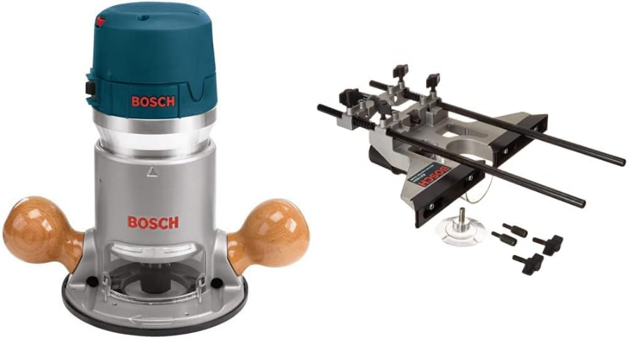
This router is part of Bosch’s 1617 series, known for its reliability and durability. It comes with a comprehensive kit that includes the router base, motor, and various accessories such as a wrench, chip deflector, and collet nut. The Bosch Fixed-Base Router 1617EVSPK is ideal for projects requiring precision and power, making it an essential addition to any woodworking setup.
Symbols
IMPORTANT: Some of the following symbols may be used on your tool. Please study them and learn their meaning. Proper interpretation of these symbols will allow you to operate the tool better and safer.
Symbol | Name | Designation/Explanation |
V | Volts | Voltage (potential) |
A | Amperes | Current |
Hz | Hertz | Frequency (cycles per second) |
W | Watt | Power |
kg | Kilograms | Weight |
min | Minutes | Time |
s | Seconds | Time |
 | Diameter | Size of drillbits, grinding wheels, etc. |
n0 | No load speed | Rotational speed, at no load |
.../min | Revolutions or reciprocation per minute | Revolutions, strokes, surface speed, orbits etc. per minute |
0 | Off position | Zero speed, zero torque... |
1, 2, 3, ... I, II, III, | Selector settings | Speed, torque or position settings. Higher number means greater speed |
 | Infinitely variable selector with off | Speed is increasing from 0 setting |
 | Arrow | Action in thedirection of arrow |
 | Alternating current | Type or a characteristic of current |
 | Direct current | Type or a characteristic of current |
 | Alternating or directcurrent | Type or a characteristic of current |
 | Class II construction | Designates Double Insulated Construction tools. |
 | Earthing terminal | Grounding terminal |
 | Warning symbol | Alerts user to warning messages |
 | Ni-Cad RBRC seal | Designates Ni-Cad battery recycling program |
![]() This symbol designates that this tool is listed by Underwriters Laboratories.
This symbol designates that this tool is listed by Underwriters Laboratories.
 This symbol designates that this tool is listed by Underwriters Laboratories, and listed to Canadian Standards by Underwriters Laboratories.
 This symbol designates that this tool is listed to Canadian Standards by Underwriters Laboratories.
 This symbol designates that this tool is listed by the Canadian Standards Association.
 This symbol designates that this tool complies to NOM Mexican Standards
Functional Description
WARNING: Disconnect the plug from the power source before making any assembly, adjustments or changing accessories. Such preventive safety measures reduce the risk of starting the tool accidentally.
Specifications
- Model number:
1617 & 1618
1617EVS & 1618EVS
0 601 617 061 - Voltage rating:
120V 50 - 60Hz
120V 50 - 60Hz
220V 50 - 60Hz - Amperage rating:
11A
12A
6A - No load speed:
n0 25,000/min
n0 8,000-25,000/min
n0 25,000/min - Collet capacities:
1/4", 3/8", 1/2", 8mm
1/4”, 3/8”, 1/2”, 8mm
1/4”, 3/8”, 1/2”, 8mm
Description
The Bosch Fixed-Base Router 1617EVSPK combines power and precision in a sturdy package. The die-cast aluminum base provides stability during operation, while the robust motor ensures consistent performance across various tasks. The router features a user-friendly design with an easy-to-use depth adjustment system and a comfortable contoured grip for reduced fatigue during extended use. The variable speed control allows users to tailor the speed to the specific material they are working with, ensuring optimal results.
The router also includes a built-in chip deflector to help manage dust and debris, enhancing visibility and safety. With its comprehensive kit and durable construction, the Bosch Fixed-Base Router 1617EVSPK is well-suited for both small-scale DIY projects and larger-scale professional woodworking applications.
Bosch Fixed-Base Router 1617EVSPK Assembly
A wide assortment of router bits with different profiles is available separately. Use 1/2″ shank whenever possible, and only use good quality bits.
WARNING: To prevent personal injury, always remove the plug from power source before removing or installing bits or accessories.
INSTALLING A ROUTER BIT
Place router upside down or lay router on its side with the base resting on the bench. Another option is to remove the motor from the base before installing the bit.
- Remove the chip shield (or flip up if plunge base is attached.
- Hold the armature shaft in place with the shaft wrench (Fig. 4)
- Next, use the collet wrench to loosen the collet chuck assembly in counter-clockwise direction (viewed from under the router).
- Once you have verified that the bit’s shank is of the proper diameter for the collet to be used, insert the shank of the router bit into the collet chuck assembly as far as it will go, then back the shank out until the cutters are approximately 1/8″ to 1/4″ away from the collet nut face.
- With the router bit inserted and the shaft wrench holding the armature shaft, use the collet wrench to firmly tighten the collet chuck assembly in a clockwise direction (viewed from under the router). To ensure proper gripping of the router bit and minimize run-out, the shank of the router bit must be inserted at least 5/8″.

WARNING: When the templet guide has been removed from base, do not use router bits greater than 2″ in diameter as they will not fit through the sub-base.
WARNING: Cutter diameter must be at least 1/4” smaller than opening for the bit and cutter.
CAUTION: To prevent damage to tool, do not tighten collet without a bit.
NOTE: The bit shank and chuck should be clean and free of dust, wood, residue and grease before assembling.
REMOVING THE ROUTER BIT
- Use the shaft and collet chuck wrenches as described earlier, and turn the collet chuck assembly in a counter-clockwise direction.
- Once the collet chuck assembly is loosened continue to turn the collet chuck assembly until it pulls the collet free from its taper, and the router bit can be removed.
NOTE: The collet chuck is self-extracting; it is NOT necessary to strike the collet chuck to free the router bit.
COLLET CHUCK CARE
With the router bit removed, continue to turn the collet chuck counter-clockwise until it is free of the shaft. To assure a firm grip, occasionally blow out the collet chuck with compressed air, and clean the taper in the armature assembly shaft with a tissue or fine brush. The collet chuck is made up of two component parts as illustrated (Fig. 5); check to see that the collet is properly seated in the collet chuck nut and lightly thread the collet chuck back onto the armature shaft. Replace worn or damaged collet chucks immediately.

REMOVING MOTOR FROM BAS
(Fig. 6)
To remove motor from non-plunge bases:

- Hold router in horizontal position, open base clamp lever, depress coarse adjustment lever, and pull motor upwards until it stops.
- Turn motor counter-clockwise, and gently pull it free of base.
To remove motor from plunge base: (Fig. 7)
- Hold router in horizontal position, open base clamp lever, and pull motor upwards until it stops.
- Turn motor counter-clockwise, and gently pull it free of base.

INSTALLING MOTOR IN BASE
The motor can be installed with the switch positioned on the right or left of the base from the operator’s side (and the cord facing the opposite side of the router). Install the motor so that the switch is in the location you find to be the most easily accessible from the handles. The switch should be easier to turn “OFF” than “ON” in case of an emergency.
To install motor in non-plunge base:
- Release the base clamp lever.
Line up the arrow on the base with arrow on the motor. (Fig. 8)

- To position switch on the right side of the base, line up the base’s arrow with motor housing’s arrow that is below the cord.
- To position switch on the left, line up the base’s arrow with motor housing’s arrow that is below the switch.
- While pressing the coarse adjustment lever, slide motor into base until resistance in felt.(The base’s guide pin is now engaged into slot on motor.)
- Continue to press coarse adjustment lever, and turn the motor clockwise until it stops.
- Push the motor into the base until it reaches the approximate desired depth.
- Release the coarse adjustment lever and slide the motor forward or back as needed until the coarse adjustment system’s “catch” springs into the coarse adjustment detent notch.
- Set final height position as described below in “Operating Instructions”.
To install motor in plunge base:
- Release the base clamp lever.
- Line up the arrow on the base with arrow on the motor. (Fig. 8)
- To position switch on the right side of the base, line up the base’s arrow with arrow on the motor housing that is below the cord.
- To position switch on the left, line up the base’s arrow with arrow on the motor housing that is below the switch.
- Slide motor into base until resistance in felt.(The base’s guide pin is now engaged into slot on motor.)
- Turn the motor clockwise until it stops.
- Push the motor into the base as far as it will go.
- Fasten the base clamp lever.
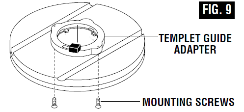
INSTALLING TEMPLET GUIDE ADAPTER
Place templet guide adapter over the holes in the center of the sub-base, and align the two threaded holes in the bottom of adapter with the countersunk holes in sub-base. Fasten adapter with the screws provided. Note that the adapter is reversible, so the release lever may be positioned as desired. (Fig. 9)
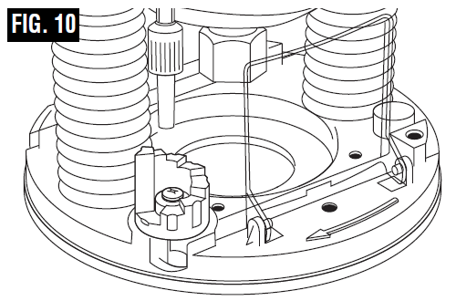
CHIP DEFLECTOR
WARNING: Always wear eye protection. The chip deflector is not intended as a safety guard.
The chip deflectors help keep dust and chips out of your face, it will not stop objects larger than dust thrown from the bit.
To remove chip shield from bases, press inward on tabs until it releases from base and remove. To attach, place deflector into position as shown in (Fig. 10). Then flex sides of deflector while pushing until it snaps into place. The plunge base’s chip shield can also be flipped out.
Operating Instructions
Bosch routers are designed for speed, accuracy and con venience in performing cabinet work, routing, fluting, beading, cove-cutting, dove tails, etc. They will enable you to accomplish inlay work, decorative edges and many types of special carving.
Bosch routers are designed for speed, accuracy and convenience in performing cabinet work, routing, fluting, beading, covecutting, dove tails, etc. They will enable you to accomplish inlay work, decorative edges and many types of special carving.
DEPTH ADJUSTMENT WITH FIXED BASE
Your router is equipped with a true micrometer type fine adjustment mechanism, which can be used in any position and provides precise adjustment of the router bit position for unmatched accuracy. When the tool is lowered to the approximate position desired, this device may be adjusted to precisely set the final bit position.
Your router also features three horizontal notches on both sides of the motor housing for coarse adjustments. The notches are spaced 1/2" apart which allows you to quickly lower or raise the tool depth in three 1/2" increments.(Approximately 12.7 mm), by simply depressing the coarse adjustment release lever
TO ADJUST DEPTH
NOTE: All depth adjustments must be made with the base clamp lever released.
Hold the tool in a horizontal position with the base clamp lever facing you.
Open the base clamp lever to release the motor.
COARSE ADJUSTMENT:
To make a large depth adjustment, depress coarse adjustment release lever and raise or lower to desired depth. There are three notches in the motor housing which are spaced 1/2″ to facilitate this adjustment.FINE DEPTH ADJUSTMENT:
To use the fine adjustment feature, turn the fine adjustment knob clockwise to lower the router bit or counter-clockwise to raise it.
NOTE: Be sure coarse adjustment lever is engaged in one of the coarse adjustment notches before making a fine adjustment.
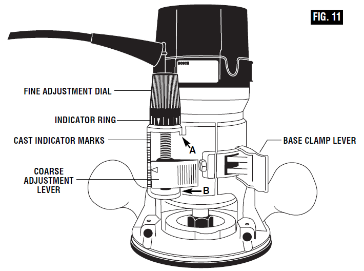
To allow precise settings, the indicator ring is graduated in English and Metric increments.(Note: one full turn of fine adjustment knob = 1/16″ or approximately 1.5 mm. The fine adjustment mechanism has a total adjustment range of 7/8″ (23 mm). Each cast indicator mark next to coarse adjustment lever is equal to 1/8″
To prevent damage to tool, avoid wedging the coarse adjustment lever against the upper A or lower B portion of the housing as shown in figure 10.After making depth adjustments, re-clamp the motor.
The indicator ring may be reset to zero without moving the fine adjustment knob, to allow the user to begin the adjustment from any reference point desired.
When the router is installed in a router table, it can be adjusted with a 1/8” hex wrench, not included with all models. (See page 21).
The RA1002 Fine Adjustment Control Extension, an optional accessory for the non- plunge bases, allows fine adjustment from beyond the top of the motor housing. To install, simply press the RA1002 into the end of the base’s own fine adjustment knob. (Fig. 11)
TO CLAMP MOTOR
When final coarse and fine adjustments have been made, fasten the base clamp lever to secure adjustments. (If additional clamping force is desired: using a 10 mm wrench, rotate clamp nut clockwise SLIGHTLY (1/8 turn or less), then test clamp. Do not over-tighten.)
DEEP CUTS
For deeper cuts, make several progressively deeper cuts by starting at one depth and then make several subsequent passes, increasing the cutting depth with each pass.
To be certain that your depth settings are as desired, you may want to make test cuts in scrap material before beginning work.
DEPTH ADJUSTMENT WITH PLUNGE
BASE PLUNGING ACTION
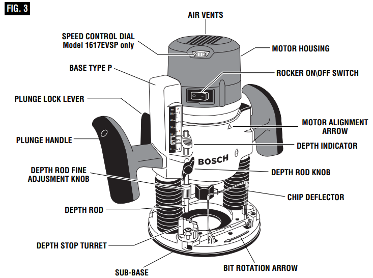
The plunge feature simplifies depth adjustments and will allow the cutting bit to easily and accurately enter the workpiece. To lower, push plunge lock lever to the left, apply downward pressure until you reach desired depth, and release pressure on lever to lock (Fig. 12). The plunge lock lever is spring loaded and returns automatically to the locked position. To raise the router, push plunge lock lever to the left, release pressure on router and the router will automatically retract the bit from the workpiece. It is advisable to retract the bit whenever it is not engaged in work piece.

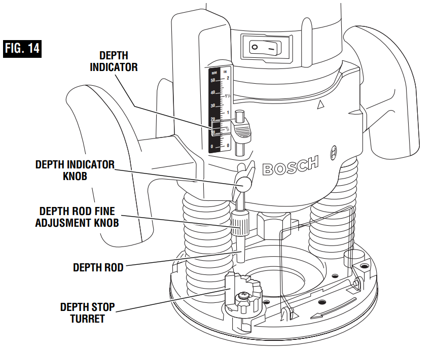
DEPTH ROD AND TURRET
The depth rod and the depth stop turret are used to control cutting depth as follows;
- With the bit installed, gently lower the motor until the tip of the router bit just contacts the level surface the router is sitting on. This is the “zero” position, from which further depth adjustments can be accurately made.
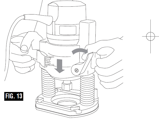
- To set a desired depth of cut, rotate depth stop turret until the lowest step is aligned with the depth rod. Loosen depth indicator knob and lower the depth rod until it contacts the lowest step of the turret. Slide the depth indicator until the red line indicates zero on the depth scale, indicating the point at which the bit just contacts the work (Fig. 13).
- To set a desired cutting depth, slide the depth rod up until the red depth indicator line attains the desired cutting depth, and secure the rod in position by firmly tightening the depth indicator knob.
- The desired depth of cut may now be achieved by plunging the router until the depth rod contacts the selected stop on the turret.
DEEP CUTS
For deeper cuts, make several progressively deeper cuts by starting with the highest step on the depth turret, and after each cut, rotate the depth turret to progressively lower steps as desired, until the final depth (lowest step or flat) is reached. Steps progress by 1/8” increments.
To be certain that your depth settings are as desired, you may want to make test cuts in scrap material before beginning work.
FINE ADJUSTMENT
The RA1166 plunge base is equipped with a fine adjustment system that allows you to micro adjust the plunge depth of the router bit for superior routing accuracy.
- Each complete revolution of the fine adjustment stop adjusts the plunging depth by 1/32”, and each of the four indicator marks on the knob represents 1/128”. One of the four tick marks is larger than the other to indicate a complete revolution. A reference indicator line is built in to the depth rod.
- To use the fine adjustment knob, once the depth rod and turret have been set, check the final depth setting and fine-adjust as follows:
- To micro-increase the plunge depth, raise the fine adjustment stop by turning it counter-clockwise by the desired amount.
- To micro-reduce the plunge depth, lower the fine adjustment stop by turning it clockwise by the desired amount.
Notes: When micro-adjusting the plunge depth, it is more convenient to move the fine adjustment stop up than down. Before setting the depth rod and turret, make sure the fine adjustment stop has been turned several revolutions down from its top position so that it can be adjusted upward. The fine adjustment stop cannot be use to reduce the plunge depth when the depth rod is already touching the depth stop turret.
The router must be raised before such an adjustment can be made.
Also available is an alternative turret that has an adjustable step which uses an M4 screw for the adjustable step. The adjustable step makes it possible to make multiple-pass applications without having to make a fine depth adjustment even when the total cutting depth is not a multiple of 1/8″.
ROCKER “ON/OFF” SWITCH
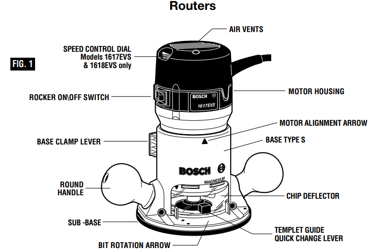
- Your tool can be turned “ON” or “OFF” by the rocker switch located on the motor housing. One side of the switch is marked “I” for “ON“, and the other side of switch is marked “O” for “OFF“. Also the edge of switch displays red when switch is in the “ON“ position.
- TO TURN THE TOOL “ON”: Push the side of the switch marked “I”.
- TO TURN THE TOOL “OFF”: Push the side of the switch marked “O”.
- Always hold the router off the work when turning the switch on or off. Contact the work with the router after the router has reached full speed, and remove it from the work before turning the switch off. Operating in this manner will prolong switch and motor life and will greatly increase the quality of your work (Fig. 1).
ROCKER POWER “ON-OFF” WITH TRIGGER SWITCH AND “LOCK- ON”BUTTON
(Model 1618EVS only)
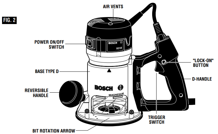
The power is switched “ON” by the rocker switch located on the top of the motor housing as described above. Now your tool can be turned “ON” or “OFF” by squeezing or releasing the trigger. Your tool is also equipped with “Lock-ON” button located just above the trigger that allows continuous operation without holding the trigger (Fig. 2).
TO LOCK SWITCH ON: Squeeze trigger, depress button and release trigger.
TO UNLOCK THE SWITCH: Squeeze trigger and release it without depressing the “Lock-ON” button.
WARNING: If the “Lock- ON” button is continuously being continuously being depressed, the trigger cannot be released.
On model 1617 hold the tool with both hands while starting the tool, since torque from the motor can cause the tool to twist.
SOFT START FEATURE
(Models 1617EVS & 1618EVS only) Electronic feedback control minimizes torque twist customary in larger routers by limiting the speed at which motor starts.
ELECTRONIC VARIABLE SPEED CONTROL
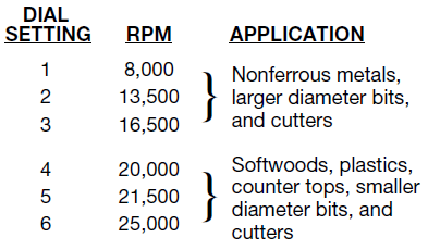
(Models 1617EVS & 1618EVS only) The electronic speed control feature allows motor speed to be matched to cutter size and material hardness for improved finish, extended bit life, and higher performance. Speed changes are achieved by rotating Control Dial RIGHT to increase speed, LEFT to decrease as indicated on housing (Fig. 1). Speed may be changed while tool is on. The reference numbers on the dial facilitate re-setting control to desired speed.
The speed chart indicates the relationship between settings and application, exact settings are determined by operator experience and preference. The bit manufacturer may also have a speed recommendation.
CONSTANT RESPONSE™ CIRCUITRY
(Models 1617EVS & 1618EVS only) The router’s Constant Response™ Circuitry monitors and adjusts power to maintain the desired RPM for consistent performance and control.
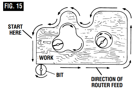
FEEDING THE ROUTER
As seen from the top of the router, the bit turns clockwise and the cutting edges face accordingly. Therefore, the most efficient cut is made by feeding the router so that the bit turns into the work, not away. Figure 14 shows proper feed for various cuts. How fast you feed depends on the hardness of the material and the size of the cut. For some materials, it is best to make several cuts of increasing depth.
If the router is hard to control, heats up, runs very slowly or leaves an imperfect cut, consider these causes:
- Wrong direction of feed — hard to control.
- Feeding too fast — overloads motor.
- Dull bit — overloads motor.
- Cut is too large for one pass — overloads motor.
- Feeding too slow — leaves friction burns on work.
Feed smoothly and steadily (do not force). You will soon learn how the router sounds and feels when it is working best.
RATE OF FEED
When routing or doing related work in wood and plastics, the best finishes will result if the depth of cut and feed rate are regulated to keep the motor operating at high speed. Feed the router at a moderate rate. Soft materials require a faster feed rate than hard materials.
The router may stall if improperly used or overloaded. Reduce the feed rate to prevent possible damage to the tool. Always be sure the collet chuck is tightened securely before use. Always use router bits with the shortest cutting length necessary to produce the desired cut. This will minimize router bit run-out and chatter.
GUIDING THE ROUTER
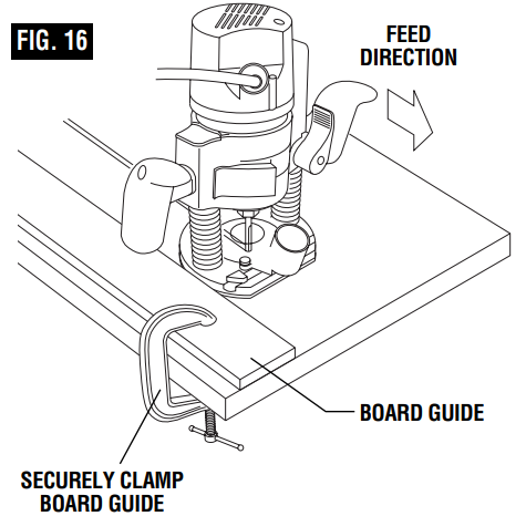
The router can be guided through the work in any of several ways. The method you use depends, of course, on the demands of the particular job and on convenience.
For routing operations such as grooving or doing, it is often necessary to guide the tool in a line parallel to a straight edge. One method of obtaining a straight cut is to securely clamp a board or other straightedge to the work surface, and guide the edge of the router sub-base along this path (Fig. 16).
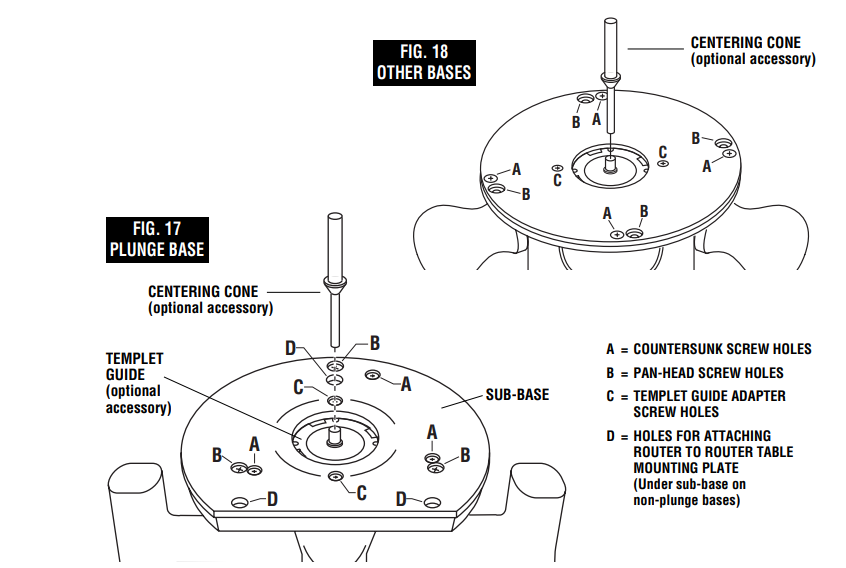
CENTERING THE SUB-BASE AND TEMPLET GUIDES
Your router features the Bosch “Precision Centering Design”. Its sub-base is precisely centered at the factory. This positions the bit at the center of the sub-base and optional templet guides. Precision centering allows you to closely follow jigs such as straight guides, templets, and dovetail fixtures without worrying about bit walk-off from the intended cut line for any reason, including the orientation of the router’s handles.
In the event the sub-base screws are loosened or removed, such when preparing the router for use in a router table, here's how to re-center the sub-base when reattaching it:
To quickly re-center the sub-base, attach the sub-base using the set of flathead screws (included) and the countersunk screw holes in the sub-base. (Flathead screws have the tapered heads.) The flathead screws and countersunk holes will pull the sub-base into a position that is very close to centered.
OR — To most precisely re-center the sub-base, attach the sub-base using the optional Bosch centering cone, an optional Bosch templet guide, and the set of pan-head screws (included). (Pan-head screws have rounded tops.) Follow steps 1-8.
- Position the sub-base so that its pan-head screw holes are over the matching set of threaded holes in the base.
- Insert the pan-head screws, not the flathead screws, through the sub-base and tighten them until they are snug, but still allow the sub-base to move
- Insert templet guide (optional accessory) the installed template guide adapter as described elsewhere in this manual.
- Slide centering cone (optional accessory) through templet guide and into collet. Use narrow end of cone when inserting into 1/4” collet, wider end of cone when inserting into 1/2” collet
- Tighten collet nut with fingers to put slight grip on centering cone
- Lightly press centering cone into templet guide to center guide and sub-base.
- Tighten the pan-head screws.
- Remove centering cone. The precision centering of the templet guide and sub-base is complete
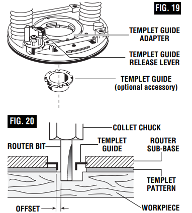
TEMPLET GUIDES
This router can also be used with the optional Bosch-exclusive quick-change templet guide system, which firmly grips the guides with a spring-loaded ring. Unlike conventional threaded templet guides, there is no threaded ring that can come loose while routing.
Templet guides are used with a number of special accessories, such as hinge templets, which are listed in your BOSCH catalog. In addition, special templets are easily prepared for cutting repeated patterns, special designs, inlays, and other applications. A templet pattern may be made of plywood, hardboard, metal or even plastic, and the design can be cut with a router, jigsaw, or other suitable cutting tool. Remember that the pattern will have to be made to compensate for the distance between the router bit and the templet guide (the “offset”), as the final workpiece will differ in size from the templet pattern by that amount, due to the bit position (Fig. 20).
ROUTER DUST COLLECTION
There are three optional dust extraction hood accessories. Each dust extraction hood is sized to accept 35mm vacuum hoses. Each accessory pack includes the VAC002 adapter that will connect the hood to 1-1/4” and 1-1/2” vacuum hoses. An adapter to connect the hood to 2-1/2" hoses is also available separately.
ROUTER DUST COLLECTION FOR PLUNGE BASE
The RA1174 dust extraction hood is designed for use the plunge base (RA1166) when routing is done in the middle of the workpiece, such as when creating slots or routing patterns for inlays. If you have a shop vacuum system, you can attach the dust extraction hood for improved visibility, accuracy and utility, particularly in freehand routing.
To attach, position as shown and secure adapter to base with the thumbscrews provided (Fig. 21).
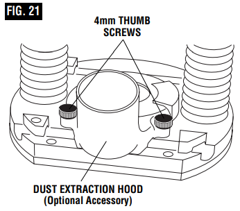
- The dust extraction hood can also be installed with the hose outlet facing the front of the tool. If the templet guide adapter is installed, it will need to be reversed or removed to allow the release lever to fit under the dust hood.
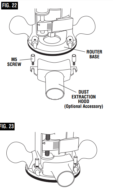
RA1171 DUST EXTRACTION HOOD FOR OTHER BASES
WARNING or plugged in. To avoid entangling hoses, do not use this dust extraction hood at the same time as any other dust extraction hood.
- The RA1171 dust extraction hood is designed for use with Bosch routers bases “S” (RA1160) and “D” (RA1162), when the routing is done in the middle of the workpiece, such as when creating slots or routing out patterns for inlays.
- To attach the hood to the router base, slide the hood into the backside of the router base with the hood’s rounded corners facing up (Fig. 22 & 23). Securely tighten the two knurled thumbscrews.
- For maximum dust collection effectiveness, make sure the router’s chip shield is in place.
RA1170 EDGEFORMING DUST EXTRACTION HOOD
WARNING bit while the router is ON or plugged in. To avoid entangling hoses, do not use this dust extraction hood at the same time as any other dust extraction hood.
The RA1170 dust extraction hood (optional accessory) is used for dust collection when edge-forming (Fig. 24).
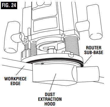
ATTACHING DUST EXTRACTION HOOD
You can attach the edge-forming hood in several places according to your needs or preferences. This hood is attached using two of the screw holes on the router base that are used to attach the router’s sub-base. Choose the desired location for the hood. Loosen and take out the two screws from the router base and attach the dust extraction hood — over the router’s sub-base — using the screws provided with the hood. Securely tighten the screws. (Figures 25 & 26).
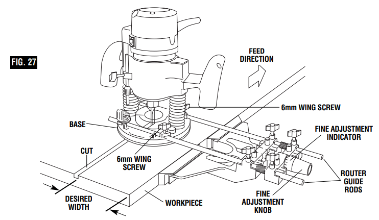
DELUXE ROUTER GUIDE
(Not included, available as accessory) The Bosch deluxe router guide is an optional accessory that will guide the router parallel to a straight edge or allow you to create circles and arcs.
- The deluxe router guide is supplied with two rods and screws to fasten the guide (Fig. 27). In addition, it features a fine adjustment knob and indicator for accurately positioning the edge guide relative to the bit. With the guide installed and adjusted, the router should be fed normally, keeping the guide in contact with the edge of the workpiece at all times. The deluxe router guide may also be positioned directly under the router base for operations where a cut is needed close to or at the edge of the work.
- The deluxe router guide includes a dust extraction hood and the VAC002 vacuum hose adapter.
- For complete instructions on installation and operation, please refer to the instructions which are included with this accessory.
USE IN ROUTER TABLE
Your router can also be used in a router table. The RA1161 fixed base is designed to allow easy depth adjustment in a table. The RA1162 “D” D-Handle base will not fit in most router tables.
CAUTION: The RA1166 Plunge Base is not recommended for use in a router table. Damage to plunge router base may occur.
To eliminate the hassle of installing your router’s own base on the router table and later having to convert it back for non-table use, Bosch offers the optional RA1165 Undertale Router Base (Fig. 28). The RA1165 base is designed to be permanently attached your router table, leaving your other router bases ready for non-table use. The motor can be quickly moved from base to base — without any tools!
The undertable base accessory includes the screws needed to fasten the base to a router table mounting plate, as well as a T-hex wrench for above-table depth adjustment.
ATTACHING BASE TO MOUNTING PLATE
Attach the RA1161 to the router table’s mounting plate using either or both sets of enclosed mounting screws.
The base has two sets of threaded holes for mounting the base:
Three 10-24 holes in industry-standard 3-hole pattern.
Four M4 holes in Bosch 4-hole pattern.
Mounting screws required for the RA1161:(not included with all models).Three 10-24 screws.
Four M4 screws.
The length will depend on the thickness of your router table or router table mounting plate.
If your router table mounting plate does not have countersunk holes in either of those patterns, you will need to determine the hole locations, drill and countersink them, also locate and drill a hole for the over-table adjustment wrench.
CONNECT THE ROUTER AND THE ROUTER TABLE SWITCH
To prepare for use of the switch,
- Make sure the router switch and the router table switch are both turned off.
- Plug the router table switch cord to wall outlet.
- Plug the router into the “pigtail” socket on the router table switch.
- Lock router switch on: squeeze trigger, depress lock-on button, and release trigger.
- Use the router table switch to start and stop the router.
FEEDING THE WORKPIECE ON A ROUTER TABLE
Always use your router table’s fence or starter pin and the appropriate guard and follow the router table’s instruction manual. ALWAYS feed the workpiece from right to left across the front of the bit. On Bosch router tables, the correct feed direction is also shown on fence housing and on the featherboards, when they have been properly installed. (Fig. 29)
Whenever possible, when using the fence, use a push stick to push the workpiece, especially when working with narrow pieces.
For complete instructions on operation of a router in a router table, please refer to the instructions that come with the router table.

TOP VIEW
NOTE: For clarity, guard and featherboard removed from drawing.
Setup Guide
To set up and operate the Bosch Fixed-Base Router 1617EVSPK:
- Unpack all components from the kit and ensure all parts are included.
- Attach the base to the motor using the provided screws and tighten securely.
- Insert the bit into the collet and secure it using the wrench and collet nut.
- Adjust the depth setting according to your project requirements using the depth adjustment knob.
- Plug in the router and test it at a low speed before proceeding with your project.
- Always use protective gear such as safety glasses and a dust mask when operating power tools.
Maintenance
Service
WARNING Preventive maintenance performed by unauthorized per onnel may result in misplacing of internal wires and components which could cause serious hazard. We recommend that all tool service be performed by a Bosch Factory Service Center or Authorized Bosch Service Station.
TOOL LUBRICATION
Your Bosch tool has been properly lubricated and is ready to use. It is recommended that tools with gears be regressed with a special gear lubricant at every brush change.
CARBON BRUSHES
The brushes and commutator in your tool have been engineered for many hours of dependable service. To maintain peak efficiency of the motor, we recommend every two to six months the brush es be examined. Only genuine Bosch replacement brushes specially designed for your tool should be used.
BEARINGS
After about 300-400 hours of operation, or at every second brush change, the bearings should be replaced at Bosch Factory Service Center or Au thorized Bosch Service Station. Bearings which become noisy (due to heavy load or very abrasive material cut ting) should be replaced at once to avoid overheating or motor failure.
Cleaning
WARNING: To avoid accidents always dis connect the tool from the power supply before cleaning or performing any maintenance. The tool may be cleaned most effectively with compressed dry air. Always wear safety gog gles when cleaning tools with compressed air.
Ventilation openings and switch levers must be kept clean and free of foreign matter. Do not at tempt to clean by inserting pointed objects through openings.
CAUTION: Certain cleaning agents and sol vents damage plastic parts. Some of these are: gasoline, carbon tetrachlo ride, chlorinated cleaning solvents, ammonia and house hold detergents that contain ammonia.
Accessories
WARNING If an extension cord is necessary, a cord with adequate size conductors that is capable of carrying the current necessary for your tool must be used. This will prevent excessive voltage drop, loss of power or overheating. Grounded tools must use 3-wire extension cords that have 3-prong plugs and receptacles.
NOTE: The smaller the gauge number, the heavier the cord.
RECOMMENDED SIZES OF EXTENSION CORDS 120 VOLT ALTERNATING CURRENT TOOLS
| Tool’s Ampere Rating | Cord Size in A.W.G. | Wire Sizes in mm² |
|---|---|---|
| Cord Length in Feet | Cord Length in Meters | |
| 25 | 50 | |
| 3-6 | 18 | 16 |
| 6-8 | 18 | 16 |
| 8-10 | 18 | 16 |
| 10-12 | 16 | 16 |
| 12-16 | 14 | 12 |
- 1/4” Collet Chuck *
- 1/2” Collet Chuck *
- 16 mm Shaft Wrench *
- 24 mm Collet Nut Wrench *
- 3/8” Collet Chuck **
- 8 mm Collet Chuck **
- Deluxe Router Guide **
- Centering Cone **
- Carry Case (Std with 1617K, 1617EVSK, 1617PK, 1617EVSPK only)
- Dust Extraction Hoods **
- Edge-Forming Dust Extraction Hood **
- Fine Adjustment Control Extension **
- Undertable Base with Fine Adjustment Control Extension **
- Router Tables **
- Quick-Release Templet Guides **
- Adapter for Standard-Style Templet Guides **
(*= standard equipment)
(**= optional accessories)
Important Safety Instructions
Read all safety warnings and instructions before operating the tool to reduce risks of electric shock, fire, and/or serious injury. It is important to save all warnings and instructions for future reference.
General Power Tool Safety Warnings
WARNING: Read all safety warnings and all instructions. Failure to follow the warnings and instructions may result in electric shock, fire and/or serious injury.
SAVE ALL WARNINGS AND INSTRUCTIONS FOR FUTURE REFERENCE
The term “power tool” in the warnings refers to your mains-operated (corded) power tool or battery-operated (cordless) power tool.
Work area safety
- Keep work area clean and well lit. Cluttered or dark areas invite accidents.
- Do not operate power tools in explosive atmospheres, such as in the presence of flammable liquids, gases or dust. Power tools create sparks which may ignite the dust or fumes.
- Keep children ad bystanders away while operating a power tool. Distractions can cause you to lose control.
Electrical safety
- Power tool plugs must match the outlet. Never modify the plug in any way. Do not use any adapter plugs with earthed (grounded) power tools. Unmodified plugs and matching outlets will reduce risk of electric shock
- Avoid body contact with earthed or grounded surfaces such as pipes, radiators, ranges and refrigerators. There is an increased risk of electric shock if your body is earthed or grounded.
- Do not expose power tools to rain or wet conditions. Water entering a power tool will increase the risk of electric shock.
- Do not abuse the cord. Never use the cord for carrying, pulling or unplugging the power tool. Keep cord away from heat, oil, sharp edges or moving parts. Damaged or entangled cords increase the risk of electric shock.
- When operating a power tool outdoors, use an extension cord suitable for outdoor use. Use of a cord suitable for outdoor use reduces the risk of electric shock.
- If operating a power tool in a damp location is unavoidable, use a Ground Fault Circuit Interrupter (GFCI) protected supply. Use of an GFCI reduces the risk of electric shock.
Personal safety
- Stay alert, watch what you are doing and use common sense when operating a power tool. Do not use a power tool while you are tired or under the influence of drugs, alcohol or medication. A moment of inattention while operating power tools may result in serious personal injury.
- Use personal protective equipment. Always wear eye protection. Protective equipment such as dust mask, non-skid safety shoes, hard hat, or hearing protection used for appropriate conditions will reduce personal injuries.
- Prevent unintentional starting. Ensure the switch is in the off-position before connecting to power source and / or battery pack, picking up or carrying the tool. Carrying power tools with your finger on the switch or energizing power tools that have the switch on invites accidents.
- Remove any adjusting key or wrench before turning the power tool on. A wrench or a key left attached to a rotating part of the power tool may result in personal injury.
- Do not overreach. Keep proper footing and balance at all times. This enables better control of the power tool in unexpected situations.
- Dress properly. Do not wear loose clothing or jewelry. Keep your hair, clothing and gloves away from moving parts. Loose clothes, jewelry or long hair can be caught in moving parts.
- If devices are provided for the connection of dust extraction and collection facilities, ensure these are connected and properly used. Use of dust collection can reduce dust-related hazards.
Power tool use and care
- Do not force the power tool. Use the correct power tool for your application. The correct power tool will do the job better and safer at the rate for which it was designed.
- Do not use the power tool if the switch does not turn it on and off. Any power tool that cannot be controlled with the switch is dangerous and must be repaired.
- Disconnect the plug from the power source and/or the battery pack from the power tool before making any adjustments, changing accessories, or storing power tools. Such preventive safety measures reduce the risk of starting the power tool accidentally.
- Store idle power tools out of the reach of children and do not allow persons unfamiliar with the power tool or these instructions to operate the power tool. Power tools are dangerous in the hands of untrained users.
- Maintain power tools. Check for misalignment or binding of moving parts, breakage of parts and any other condition that may affect the power tool’s operation. If damaged, have the power tool repaired before use. Many accidents are caused by poorly maintained power tools.
- Keep cutting tools sharp and clean. Properly maintained cutting tools with sharp cutting edges are less likely to bind and are easier to control.
- Use the power tool, accessories and tool bits etc. in accordance with these instructions, taking into account the working conditions and the work to be performed. Use of the power tool for operations different from those intended could result in a hazardous situation.
Service
Have your power tool serviced by a qualified repair person using only identical replacement parts. This will ensure that the safety of the power tool is maintained.
Safety Rules for Routers
- Hold power tool by insulated gripping surfaces, because the cutter may contact hidden wiring or its own cord. Contact with a ”live” wire will make exposed metal parts of the tool ”live” and shock the operator.
- Use clamps or another practical way to secure and support the workpiece to a stable platform. Holding the work by your hand or against the body leaves it unstable and may lead to loss of control.
- Do not drill, fasten or break into existing walls or other blind areas where electrical wiring may exist. If this situation is unavoidable, disconnect all fuses or circuit breakers feeding this worksite.
- Always make sure the work surface is free from nails and other foreign objects. Cutting into a nail can cause the bit and the tool to jump and damage the bit.
- Never hold the workpiece in one hand and the tool in the other hand when in use. Never place hands near or below cutting surface. Clamping the material and guiding the tool with both hands is safer.
- Never lay workpiece on top of hard surfaces, like concrete, stone, etc… Protruding cutting bit may cause tool to jump.
- Always wear safety goggles and dust mask. Use only in well ventilated area. Using personal safety devices and working in safe environment reduces risk of injury.
- After changing the bits or making any adjustments, make sure the collet nut and any other adjustment devices are securely tightened. Loose adjustment device can unexpectedly shift, causing loss of control, loose rotating components will be violently thrown.
- Never start the tool when the bit is engaged in the material. The bit cutting edge may grab the material causing loss of control of the cutter.
- Always hold the tool with two hands during start-up. The reaction torque of the motor can cause the tool to twist.
- The direction of feeding the bit into the material is very important and it relates to the direction of bit rotation. When viewing the tool from the top, the bit rotates clockwise. Feed direction of cutting must be counter-clockwise. NOTE: inside and outside cuts will require different feed direction, refer to section on feeding the router. Feeding the tool in the wrong direction, causes the
- cutting edge of the bit to climb out of the work and pull the tool in the direction of this feed.
- Never use dull or damaged bits. Sharp bits must be handled with care. Damaged bits can snap during use. Dull bits require more force to push the tool, possibly causing the bit to break.
- Never touch the bit during or immediately after the use. After use the bit is too hot to be touched by bare hands.
- Never lay the tool down until the motor has come to a complete standstill. The spinning bit can grab the surface and pull the tool out of your control.
- Never use bits that have a cutting diameter greater than the opening in the base.
- The rated speed of the accessory must be at least equal to the maximum speed marked on the power tool. Accessories running faster than their RATED SPEED can break and fly apart.
Additional Safety Warnings
- GFCI and personal protection devices like electrician’s rubber gloves and footwear will further enhance your personal safety.
- Do not use AC only rated tools with a DC power supply. While the tool may appear to work, the electrical components of the AC rated tool are likely to fail and create a hazard to the operator.
- Keep handles dry, clean and free from oil and grease. Slippery hands cannot safely control the power tool.
- Use clamps or other practical way to secure and support the workpiece to a stable platform. Holding the work by hand or against your body leaves it unstable and may lead to loss of control.
- Develop a periodic maintenance schedule for your tool. When cleaning a tool be careful not to disassemble any portion of the tool since internal wires may be misplaced or pinched or safety guard return springs may be improperly mounted. Certain cleaning agents such as gasoline, carbon tetrachloride, ammonia, etc. may damage plastic parts.
- Risk of injury to user. The power cord must only be serviced by a Bosch Factory Service Center or Authorized Bosch Service Station.
WARNING: Some dust created by power sanding, sawing, grinding, drilling, and other construction activities contains chemicals known to cause cancer, birth defects or other reproductive harm. Some examples of these chemicals are:
- Lead from lead-based paints,
- Crystalline silica from bricks and cement and other masonry products, and
- Arsenic and chromium from chemically-treated lumber.
Your risk from these exposures varies, depending on how often you do this type of work. To reduce your exposure to these chemicals: work in a well ventilated area, and work with approved safety equipment, such as those dust masks that are specially designed to filter out microscopic particles.
Safety Rules for Router Table
Read and understand the tool manual and these instructions for the use of this table with your router. Failure to follow all instructions listed below may result in serious personal injury.
- Unplug tool before setting up in table, making adjustments or changing bits. Accidental start-up of the tool can cause injury.
- Fully assemble and tighten all the fasteners required for this table and mounting the router. Also remember to occasionally check the stand and make sure it is still tight. A loose stand is unstable and may shift in use and cause serious injury.
- Before operating make sure the entire unit is placed on a solid, flat, level surface. Serious injury could occur if tool is unstable and tips.
- Never stand on the table or use as ladder or scaffolding. Serious injury could occur if the table is tipped or the cutting tool is accidentally contacted. Do not store materials on or near the table such that it is necessary to stand on the table or its stand to reach them.
- Never use dull or damaged bits. Sharp bits must be handled with care. Damaged bits can snap during use. Dull bits require more force to push the workpiece, possibly causing the bit to break.
- Match the appropriate bit and its speed to your application. Do not use bits that have a cutting diameter that exceeds the capacity of the tool.
- Overloading the tool can lead to personal injury or tool failure.
- Never start the tool when the bit is engaged in the material. The bit cutting edge may grab the material causing loss of control of the workpiece.
- Router bits are intended for wood, wood products and plastic only. Be sure the workpiece does not contain nails, etc. before routing. Cutting a nail or the like will cause the carbides to be dislodged, fly toward the operator side, and possibly strike you or bystanders.
- Feed the workpiece against the rotation of the bit. The bit rotates counter-clockwise as viewed from the top of table. Feeding the work in the wrong direction will cause the workpiece to “climb” up on the bit and may lead to loss of control during operation.
- Never place hands near the spinning bit. Use push sticks, vertical and horizontally mounted feather boards (spring sticks) and other jigs to hold down the workpiece and keep your hands away from the spinning bit. Router cuts are blind cuts but the bit still protrudes through the table and you must be aware of the position of your hands relative to the spinning bit.
- We do not recommend cutting material that is warped, wobbly or otherwise unstable. If this situation is unavoidable always cut the material with the concave side against the table. Cutting the material with the concave side up or away from table may cause the warped or wobbly material to roll; causing you to lose control, kickback and serious personal injury may result.
- Use the adjustable fence in straight cutting applications. When routing along an entire edge of the work, the fence, fence faces, and adjustable outfeed fence support shims will help maintain stability.
- When the table is used without the fence, piloted bits (or “bearing bits”) must be used. Piloted bits are used when routing internal and external contours on a workpiece. The bearing of the piloted bit assists in maintaining control of the workpiece. Whenever possible, the starter pin should also be used.
- After changing the bits or making any adjustments, make sure the collet nut and any other adjustment devices are securely tightened. Loose adjustment device can unexpectedly shift, causing loss of control, loose rotating components will be violently thrown.
- Never touch the bit during or immediately after the use. Contact with a spinning bit will cause injury and after use the bit is too hot to be touched by bare hands.
- Use only Bosch replacement parts. Any others may create a hazard.
Troubleshooting
Common issues and solutions for the Bosch Fixed-Base Router 1617EVSPK:
- Motor Not Turning On: Check power cord for damage or ensure proper connection to a working outlet.
- Excessive Vibration: Ensure bit is properly seated in the collet and tighten securely.
- Dust Build-Up: Regularly clean dust deflector and surrounding areas to maintain visibility.
Instructions & Warnings: Always follow safety guidelines provided in the user manual. Wear protective gear, keep loose clothing tied back, and avoid overreaching while operating the router.
Bosch Fixed-Base Router 1617EVSPK Warranty
LIMITED WARRANTY OF BOSCH PORTABLE AND BENCHTOP POWER TOOLS
Robert Bosch Tool Corporation (“Seller”) warrants to the original purchaser only, that all BOSCH portable and benchtop power tools will be free from defects in material or workmanship for a period of one year from date of purchase. SELLER’S SOLE OBLIGATION AND YOUR EXCLUSIVE REMEDY under this Limited Warranty and, to the extent permitted by law, any warranty or condition implied by law, shall be the repair or replacement of parts, without charge, which are defective in material or workmanship and which have not been misused, carelessly handled, or misreported by persons other than Seller or Authorized Service Station. To make a claim under this Limited Warranty, you must return the complete portable or benchtop power tool product, transportation prepaid, to any BOSCH Factory Service Center or Authorized Service Station. For Authorized BOSCH Power Tool Service Stations, please refer to your phone directory.
THIS LIMITED WARRANTY DOES NOT APPLY TO ACCESSORY ITEMS SUCH AS CIRCULAR SAW BLADES, DRILL BITS, ROUTER BITS, JIGSAW BLADES, SANDING BELTS, GRINDING WHEELS AND OTHER RELATED ITEMS.
Pros & Cons
Pros
- Powerful Motor: 2.25 HP motor provides ample power for various tasks.
- Variable Speed Control: Allows for precise speed adjustments based on material.
- Durable Construction: Die-cast aluminum base ensures stability and longevity.
- User-Friendly Design: Easy-to-use depth adjustment system and comfortable grip.
Cons
- Weight: The router can be heavy, especially during extended use.
- Limited Base Adjustments: Some users may find the fixed-base less versatile compared to plunge routers.
- Necessity for Additional Accessories: Users may need to purchase additional bits or accessories separately.
Customer Reviews
Customers have praised the Bosch Fixed-Base Router 1617EVSPK for its reliability, power, and ease of use. Many have noted its smooth operation and precise depth control, making it suitable for both beginners and professionals. However, some users have mentioned that it can be heavy and that additional accessories might be necessary depending on their specific needs.
Faqs
What is the motor power of the Bosch Fixed-Base Router?
What are the available collet sizes for this router?
How do I adjust the depth on this router?
Is this router suitable for professional use?
What safety precautions should I take while using this router?
Can I use different types of bits with this router?
How do I troubleshoot if my router does not turn on?
Is there a chip deflector included with this router?
Can I upgrade or modify parts of this router?
What is included in the kit?
Leave a Comment