Champion 2000W Dual Fuel Inverter Generator User Guide
Content
Introduction
With proper product knowledge, safe use, and regular maintenance, this product should bring years of satisfying service. Every effort has been made to ensure the accuracy and completeness of the information in this manual at the time of publication, and we reserve the right to change, alter,, and/or improve the product and this document at any time without prior notice.
Since CPE highly values how our products are designed, manufactured, operated,, and are serviced, and also highly values your safety and the safety of others, we would like you to take the time to review this product manual and other product materials thoroughly and be fully aware and knowledgeable of the assembly, operation, dangers,, and maintenance of the product before use. Fully familiarize yourself, and make sure others who plan on operating the product fully familiarize themselves too, with the proper safety and operation procedures before each use. Please always exercise common sense and always err on the side of caution when operating the product to ensure no accident, property damage, or injury occurs. We want you to continue to use and be satisfied with your CPE product for years to come.
When contacting CPE about parts and/or services, you will need to supply the complete model and serial numbers of your product.
Parts Included
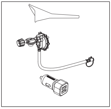
Accessories
- Oil Funnel...............................................................................1
- 2.3 ft. (0.7 m) LPG Hose with Regulator..................................1
- Dual 2.4A Port USB Adapter...................................................1
Champion 2000W Dual Fuel Inverter Generator Parts Diagram
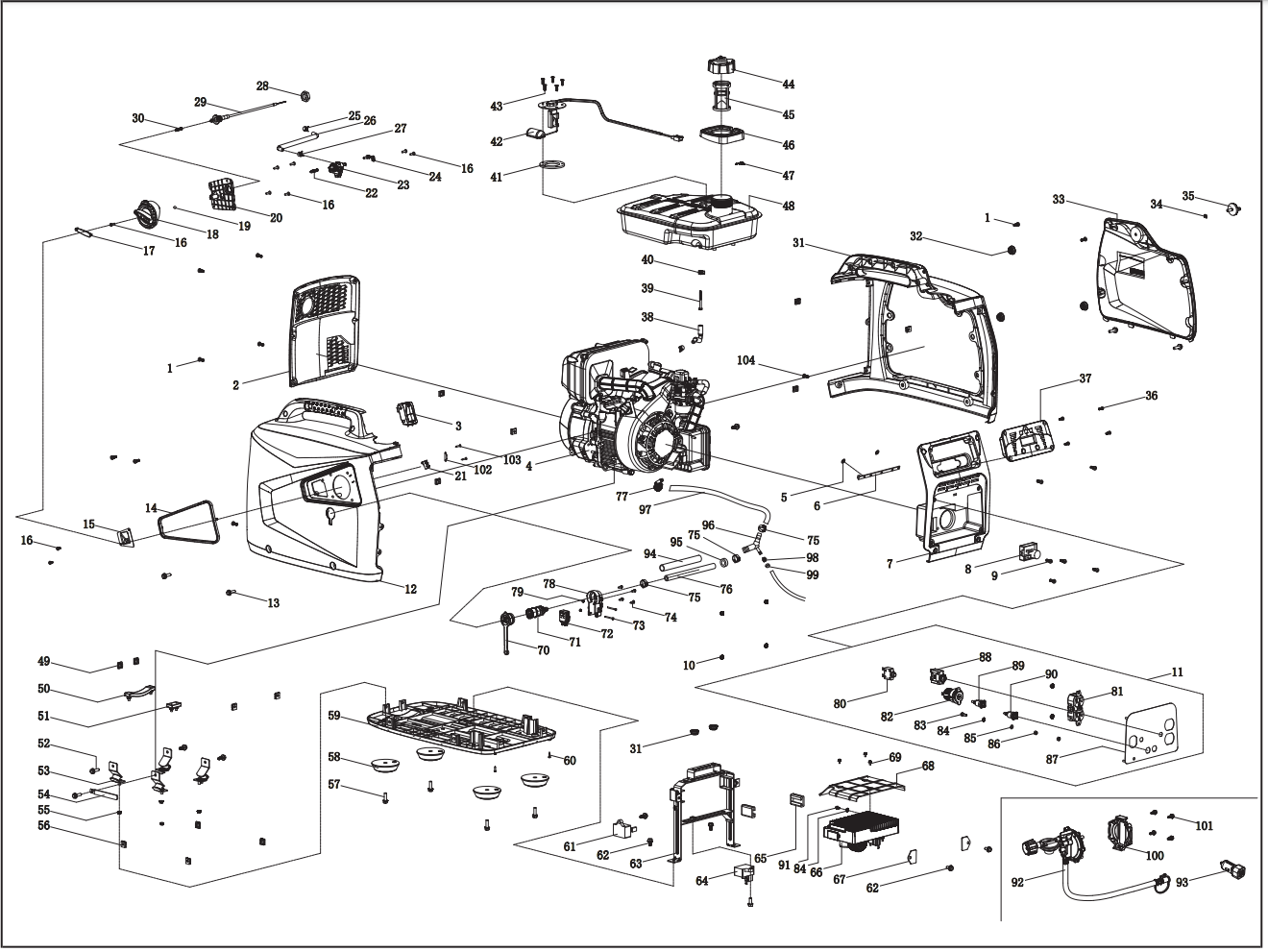
Parts List
# | Part Number | Description | Qty. |
1 | 1.818.0514.3 | Screw M5 × 14, Green | 12 |
2 | 62.200200.00 | Cover, Left, black | 1 |
3 | 62.214000.00 | Indicator Light Assembly, FuelTank | 1 |
4 | 62.490 | Engine, 80 cc | 1 |
5 | 2.03.061 | Circlip | 2 |
6 |
62.214000.01 | Indicator Light Assembly, Control Panel |
1 |
7 | 62.200300.00 | Cover, Right, black | 1 |
8 | 88.126000.00 | Ignition Assembly | 1 |
9 | 1.818.0414.3 | Screw M4 × 14 | 2 |
10 | 1.6177.1.04.1 | Lock Nut M4, Flange, Green | 6 |
11 | 100306.21 | Control Panel Assembly | 1 |
12 | 62.200101.01.48 | Front Cover, Yellow | 1 |
13 | 1.5789.0615.3 | Flange Bolt M6 × 15 | 4 |
14 | 62.200106.00 | Protection Strip | 1 |
15 | 62.061200.00 | Guide Plate, Rope | 1 |
16 | 1.823.0412.3 | Screw M4 × 12 | 9 |
17 | 62.139002.00 | Cover, Rotary Knob | 1 |
18 | 62.139001.01 | Rotary Knob | 1 |
19 | 62.139008.00 | Ball Bearing, Rotary Knob | 1 |
20 | 62.139004.01 | Fixed Plate | 1 |
21 | 5.1050.008 | Microswitch | 1 |
22 | 62.139007.00 | Spring, Steel Ball | 1 |
23 | 62.070400.01 | Fuel Valve | 1 |
24 | 62.139006.00 | Pressure Plate | 1 |
25 | 2.06.016 | Clamp, Ø8.7 × b8 | 2 |
26 | 62.070011.00 | Pipe, Fuel Valveto Carburetor | 1 |
27 | 2.06.007 | Clamp, Ø8 × b6 | 1 |
28 | 2.02.036 | Thin HexnutM16 × 1.5 | 1 |
29 | 62.130200.00 | Pull Choke Assembly | 1 |
30 | 62.130201.00 | Spring, Pull Choke | 1 |
31 | 62.200401.00.48 | Supporter, Rear Cover, Yellow | 1 |
32 | 81.200102.00 | Rotundity Jacket | 3 |
33 | 62.200402.01.48 | Protector, Rear Cover, Yellow | 1 |
34 | 1.896.05 | Split Washer Ø5 | 1 |
35 | 62.200410.00 | Rotary Knob, Protector, Rear Cover | 1 |
36 | 1.819.0414.2 | Sunk Screw M4 × 14 | 4 |
37 | 62.210017.00 | Multifunction Display | 1 |
38 | 88.070011.01 | Pipe, Fuel Tank to Valve | 1 |
39 | 111.070300.01 | Fuel Filter, Wire Mesh | 1 |
40 | 2.06.018 | Clamp, Ø10.5× b8 | 1 |
41 | 122.070036.00 | Seal Ring | 1 |
42 | 62.070035.00 | Fuel Level Sensor | 1 |
43 | 1.819.0516.2 | Sunk Screw M5 × 16 | 5 |
44 | 62.070100.00 | Fuel Tank Cap | 1 |
45 | 62.070300.00 | Fuel Filter | 1 |
46 | 62.200502.00 | Spillway, Fuel Tank | 1 |
47 | 82.080009.00 | Mustache clip | 1 |
48 | 62.071000.00 | Fuel Tank, 4.2L, Black | 1 |
49 | 2.02.010 | Cage Nut M5 | 10 |
50 | 81.200603.00 | Mount, End Cover | 1 |
51 | 81.200602.00 | Mounting Rubber, End Cover | 1 |
52 | 1.5789.0615 | Flange Bolt M6 × 15 | 6 |
53 | 81.200605.00 | Motor Mount | 4 |
54 | 2.05.050 | Clamp, Wire, 100 | 1 |
55 | 1.6177.1.06.3 | Lock Nut M6, Flange, Green | 4 |
56 | 2.02.013 | Cage Nut M6 | 4 |
57 | 1.5789.0620 | Flange Bolt M6 × 20 | 4 |
58 | 62.200604.00 | Mounting Rubber, Base Setting | 4 |
59 | 62.200601.00 | Base Setting Component | 1 |
60 | 1.845.2913 | Tapping Screw ST2.9 × 13 | 2 |
61 | 5.1800.003 | Rectifier | 1 |
62 | 1.5789.0612 | Flange Bolt M6 × 12 | 5 |
63 | 62.070045.01 | Supportor, Fuel Tank | 1 |
64 | 5.1820.004 | Charger | 1 |
65 | 81.220001.00 | Protector, Control Unit | 2 |
66 | 62.221000.00 | Control Unit, 1600W / 120V / 60HZ | 1 |
67 | 81.220003.00 | Pressure Plate, Control Unit | 2 |
68 | 62.220006.00 | AirShroud, Control Unit | 1 |
69 | 1.9074.1.0408 | Screw M4×8 | 3 |
70 | 62.200102.00 | Circular Rubber Sheath | 1 |
71 | 87.070021.02 | Inlet Connection | 1 |
72 | 5.1050.000 | Microswitch | 1 |
73 | 1.819.1.0330 | Sunk Screw M3 × 30 | 2 |
74 | 1.845.3513 | Tapping Screw ST3.5 × 13 | 4 |
75 | 2.06.048 | Clamp Ø15.7 | 3 |
76 | 62.070012.00 | Pipe 220 mm | 1 |
77 | 2.06.019 | Hose Clamp Ø15 | 1 |
78 | 62.070037.00 | Support, Inlet Connection | 1 |
79 | 1.6170.03 | Hexagon Nut M3 | 2 |
80 | 5.1200.308 | 8Amp Circuit Breaker, Push Button | 1 |
81 | 5.1120.010 | Receptacle 5-20R, Duplex | 1 |
82 | 5.1110.005 | Receptacle, DC12V | 1 |
83 | 1.5783.0516.3 | Bolt M5 × 16, Green | 1 |
84 | 1.862.05 | Lock Washer Ø5, Toothed | 2 |
85 | 1.97.1.05.3 | Washer, Ø5, Green | 1 |
86 | 1.6170.05.3 | Nut M5, Green | 2 |
87 | 62.01.1.2 | Control Panel | 1 |
88 | 5.1213.920 | 20Amp Circuit Breaker, Push Button, CSA | 1 |
89 | 83.210001.00.1 | Connect Port, Black | 1 |
90 | 83.210001.00.3 | Connect Port, Red | 1 |
91 | 1.16674.0510 | Flange Bolt M5 × 10 | 1 |
92 | 62.130000.90 | LPG Hose With Regulator, 700 mm | 1 |
93 | 9.1700.008 | Plug, USB 5V/2.4A | 1 |
94 | 5.1320.029 | Plastic Pipe 170 mm | 1 |
95 | 2.12.011 | Buffer Ring Ø15 × 9 | 1 |
96 | 62.130031.00 | Three Way Pipe | 1 |
97 | 62.070012.01 | Pipe 150 mm | 1 |
98 | 2.06.049 | Clamp Ø10.5 | 1 |
99 | 2.12.004 | Buffer RingØ9.5 × 10 | 1 |
100 | 62.138000.90 | Regulator Cover | 1 |
101 | 1.5789.0612.1 | Flange Bolt M6 × 12, black | 4 |
102 | 62.200025.00 | Pressure Plate | 1 |
103 | 1.848.2995 | Tapping Screw ST2.9 × 9.5 | 2 |
104 | 1.818.0512.3 | Screw M5 x 12, Green | 2 |
Engine Parts Diagram
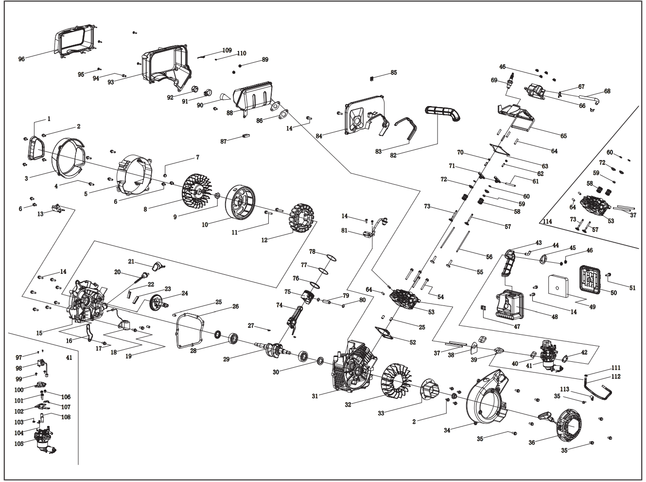
Engine Parts List
# | Part Number | Description | Qty. |
1 | 62.190006.00 | Rubber Sleeve, End Cover | 1 |
2 | 1.5789.0512 | Flange Bolt M5 × 12 | 4 |
3 | 62.190002.01 | Cover, End Housing | 1 |
4 | 1.16674.0620 | Flange Bolt M6 × 20 | 4 |
5 | 62.190002.00 | End Housing, Motor | 1 |
6 | 1.16674.0612 | Flange Bolt M6 × 12 | 5 |
7 | 24.091008.01 | End Cap | 1 |
8 | 62.190001.00 | Cooling Fan, Rotor | 1 |
9 | 2.02.018 | Nut M12 × 1.25 | 2 |
10 | 62.191100.00 | Rotor Component | 1 |
11 | 1.5789.0635 | Flange Bolt M6 × 35 | 2 |
12 | 62.191200.03 | Stator Component | 1 |
13 | 81.122000.00 | Trigger Assembly | 1 |
14 | 1.5789.0620 | Flange Bolt M6 × 20 | 12 |
15 | 81.030007.00 | Cover, Crankcase | 1 |
16 | 81.030006.00 | Plate, Coil | 1 |
17 | 1.5789.0608 | Flange Bolt M6 × 8 | 1 |
18 | 81.127000.00 | Oil Level Sensor | 1 |
19 | 1.5789.0612 | Flange Bolt M6 × 12 | 2 |
20 | 81.031000.00 | Oil Dipstick Assembly | 1 |
21 | 81.030035.00 | Oil Nipple | 1 |
22 | 81.030013.00 | Seal Strip 1, Crankcase Cover | 1 |
23 | 81.030013.01 | Seal Strip 2, Crankcase Cover | 1 |
24 | 81.040100.00 | Camshaft | 1 |
25 | 2.04.002 | Dowel Pin Ø8 × 14 | 4 |
26 | 81.030008.00 | Gasket, Crankcase Cover | 1 |
27 | 2.14.013 | Woodruff Key 3 × 5 × 13 | 2 |
28 | 1.276.6204 | Bearing 6204 | 2 |
29 | 81.050100.00 | Crankshaft | 1 |
30 | 2.11.019 | Oil Seal Ø20 × Ø35 × 5 | 2 |
31 | 81.030100.00 | Crankcase | 1 |
32 | 81.080001.00 | Cooling Fan | 1 |
33 | 81.060001.00 | Pulley, Starter | 1 |
34 | 62.080100.00 | Fan Cover | 1 |
35 | 1.5789.0615 | Flange Bolt M6 × 15 | 9 |
36 | 62.061000.00 | Recoil Assembly | 1 |
37 | 2.01.049 | Stud Bolt M6 × 99 | 2 |
38 | 81.130002.00 | Gasket, Insulator | 1 |
39 | 62.130001.00 | Insulator, Carburetor | 1 |
40 | 81.130003.00 | Gasket, Carburetor | 1 |
41 | 62.130000.03 | Carburetor Assembly | 1 |
42 | 81.130004.00 | Gasket, Air Cleaner | 1 |
43 | 81.090004.00 | Pipe, Air Cleaner | 1 |
44 | 81.090003.00 | Joint, Breather Pipe | 1 |
45 | 81.090005.00 | Pressure Plate, AirFilter Tube | 1 |
46 | 1.6177.1.06.3 | Flange Lock Nut M6 | 6 |
47 | 2.02.013 | Cage Nut M6 | 1 |
48 | 62.091100.00 | Base, Air Cleaner | 1 |
49 | 81.091003.00 | Element, Air Cleaner | 1 |
50 | 62.091200.00 | Cover, Air Cleaner | 1 |
51 | 2.08.053 | Bolt M6 × 20 | 1 |
52 | 81.030009.00 | Gasket, Cylinder Head | 1 |
53 | 62.010100.02 | Cylinder Head | 1 |
54 | 1.5789.0655 | Flange Bolt M6 × 55 | 4 |
55 | 81.040013.00 | Lifter, Valve | 2 |
56 | 81.040005.00 | Push Rod | 2 |
57 | 81.040002.00 | Valve, Intake | 1 |
58 | 83.040003.01 | Spring, Valve | 2 |
59 | 81.040017.00 | Oil Seal, Valve | 1 |
60 | 83.040014.01 | Valve Collet | 2 |
61 | 81.040016.00 | Shaft, Rocker Arm | 1 |
62 | 81.040012.00 | Screw, Valve Adjustment | 2 |
63 | 62.020002.00 | Gasket, Cylinder Head Cover | 1 |
64 | 2.01.027 | Stud Bolt M6 × 27 | 6 |
65 | 62.080200.00 | Air Shroud, Cylinder | 1 |
66 | 62.021000.00 | Cover, Cylinder Head | 1 |
67 | 2.06.010 | Clamp, Ø10.5 × Ø1 | 2 |
68 | 62.020001.00 | Breather Tube | 1 |
69 | 2.15.013 | Spark Plug E7RTC | 1 |
70 | 2.02.009 | Nut M5 × 0.5, Lock | 2 |
71 | 81.040009.00 | Rocker Arm, Intake Valve | 2 |
72 | 83.040001.01 | Retainer, Valve Spring | 2 |
73 | 81.040006.00 | Valve, Exhaust | 1 |
74 | 81.050200.00 | Connecting Rod Assembly | 1 |
75 | 81.050005.02.1 | Piston | 1 |
76 | 81.050303.02 | Ring Assembly, Oil | 1 |
77 | 81.050302.02 | Piston Ring, Second | 1 |
78 | 81.050301.02 | Piston Ring, First | 1 |
79 | 81.050003.00 | Wrist Pin, Piston | 1 |
80 | 2.09.007 | Circlip Ø13.5× Ø1 | 2 |
81 | 81.123000.01 | Ignition Coil | 1 |
82 | 81.080003.00 | Air Duct | 1 |
83 | 81.081001.00 | Muffler Protector Seal | 1 |
84 | 62.081100.00 | Muffler Protector, Side | 1 |
85 | 81.081003.00 | Fastening Insert Piece | 1 |
86 | 81.100001.00 | Gasket, Exhaust Pipe | 1 |
87 | 81.081002.00 | Rubber Seal Sleeve | 1 |
88 | 62.101100.00 | Muffler Assembly | 1 |
89 | 1.6175.06.3 | Nut M6 | 2 |
90 | 81.101300.00 | Spark Arrester | 1 |
91 | 2.06.011 | Clamp, Ø25 × b10 | 1 |
92 | 81.101501.00 | Cap, Spark Arrester | 1 |
93 | 62.081200.00 | Middle Shield, Muffler | 1 |
94 | 1.70.0616 | Inside Hexagonal Bolt M6 × 16 | 1 |
95 | 1.845.4817 | Tapping Screw ST4.8 × 17 | 4 |
96 | 62.081300.00 | Terminal Shield, Muffler | 1 |
97 | 1.818.0306.1 | Screw M3 × 6 | 2 |
98 | 62.132200.00 | Stepper Motor | 1 |
99 | 1.9074.1.0408 | Screw M4 × 8 | 2 |
100 | 81.132100.00 | Stepper Motor Base | 1 |
101 | 1.9074.4.0535 | Screw M5 × 35 | 2 |
102 | 62.130005.00 | Support, Stepper Motor | 1 |
103 | 81.130010.00 | Spring, Connecter | 1 |
104 | 81.130008.00 | Connecter, Choke Valve Axis | 1 |
105 | 81.131000.03 | Carburetor | 1 |
106 | 1.9074.3.0510 | Screw M5 × 10 | 1 |
107 | 62.130007.00 | Pressure Plate, Choke Control Line | 1 |
108 | 81.130006.00 | Brace, Support Plate | 2 |
109 | 62.080005.00 | Plate, Middle Shield | 1 |
110 | 1.845.4295 | Tapping Screw ST4.2 × 9.5 | 1 |
111 | 2.06.049 | Clip Ø10.5 | 1 |
112 | 62.070012.02 | Pipe 315 mm | 1 |
113 | 2.05.055 | Clamp Ø9.5 | 1 |
114 | 62.010000.00 | Cylinder Head Assembly | 1 |
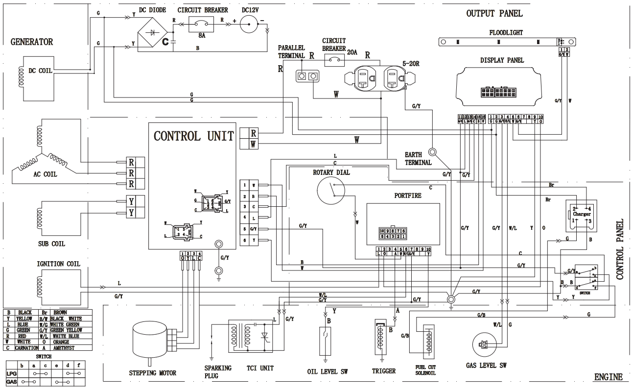
Wiring Diagram
Champion 2000W Dual Fuel Inverter Generator SPECIFICATIONS
Generator Specifications
- Generator Model: 100402
- Start Type: Manual
- Watts (Starting/Running): 2000/1600
- Watts (LPG) (Starting/Running): 1800/1440
- AC Volts: 120
- AC Amps @ 120V: 13.3
- DC Volts: 12
- DC Amps: 8
- Frequency: 60 Hz
- Phase: Single
- Gross Weight: 57.5 lb. (26.1 kg)
- Net Weight: 48.7 lb. (22.1 kg)
- Length: 20.5 in. (52 cm)
- Width: 12.8 in. (32.5 cm)
- Height: 16.9 in. (43 cm)
Engine Specifications
- Model: YF149FD-L_G
- Displacement: 80 cc
- Type: 4-Stroke OHV
Oil Specifications
- DO NOT OVERFILL.
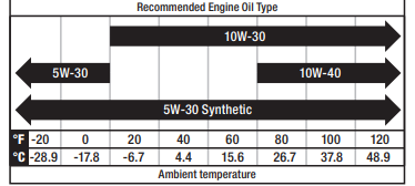
- Type: See chart below
- Capacity: 0.4 qt. (0.4 L)
NOTICE Weather will affect engine oil and engine performance. Change the type of engine oil used based on weather conditions to suit the engine's's needs.
Fuel Specifications
- Use regular unleaded gasoline with a minimum octane rating of 87 and an ethanol content of 10% or less by volume. DO NOT USE E15 or E85. DO NOT OVERFILL.
- Gasoline Capacity: 1.1 gal. (4.2 L)
Spark Plug Specifications
- OEM Type: NHSP E7RTC
- Replacement Type: NGK BPR7HS or equivalent
- Gap: 0.024-0.028 in. (0.6-0.7 mm)
Valve Specifications
- Intake Clearance: 0.004 in. (0.1 mm)
- Exhaust Clearance: 0.004 in. (0.1 mm)
NOTICE A technical bulletin regarding valve adjustment procedures is available at www.championpowerequipment.com.
Temperature Specifications
- Starting Temperature Range (°F/°C): 5 to 104/-15 to 40
NOTICE An important message about temperature: Your product is designed and rated for continuous operation at ambient temperatures up to 40°C (104°F). When your product is needed it may be operated at temperatures ranging from 5°F (-15°C) to 122°F (50°C) for short periods. If exposed to temperatures outside this range during storage, it should be brought back within this range before operation. In any event, the product must always be operated outdoors, in a well-ventilated area,, and away from doors, windows,, and vents.
SAFETY DEFINITIONS
The purpose of safety symbols is to attract your attention to possible dangers. The safety symbols, and their explanations, deserve your careful attention and understanding. The safety warnings do not by themselves eliminate any danger. The instructions or warnings they give are not substitutes for proper accident prevention measures.
- DANGER
- DANGER indicates a hazardous situation that,if not avoided, will result in death or serious injury.
- WARNING
- WARNING indicates a hazardous situation which, if not avoided, could result in death or serious injury.
- CAUTION
- CAUTION indicates a hazardous situation that, if not avoided, could result in minor or moderate injury.
- NOTICE
- NOTICE is used to address practices not related to physical injury.
IMPORTANT SAFETY INSTRUCTIONS
- WARNING: Cancer and Reproductive Harm https://www.P65Warnings.ca.gov
DANGER
Generator exhaust contains carbon monoxide, a colorless, odorless, poison gas. Breathing carbon monoxide will cause nausea, dizziness, fainting or death. If you start to feel dizzy or weak, get to fresh air immediately.
OPERATE THE GENERATOR OUTDOORS ONLY IN A WELL-VENTILATED AREA.
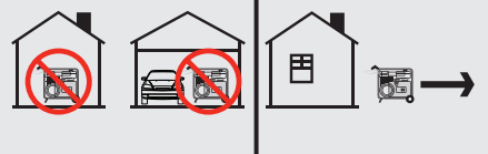
- DO NOT operate the generator inside any building, including garages, basements, crawlspaces and sheds, enclosures,, or compartments, including the generator compartment of a recreational vehicle.
- DO NOT allow exhaust fumes to enter a confined area through windows, doors, vents,, or other openings.
DANGER
Using a generator indoors CAN KILL YOU IN MINUTES. Generator exhaust contains carbon monoxide. This is a poison you cannot see or smell.
NEVER use inside a home or garage, EVEN IF doors and windows are open.
ONLY use OUTSIDE and far away from windows, doors, and vents.
Install battery-operated carbon monoxide alarms or plug-in carbon monoxide alarms with battery backup according to the manufacturer’s instructions.
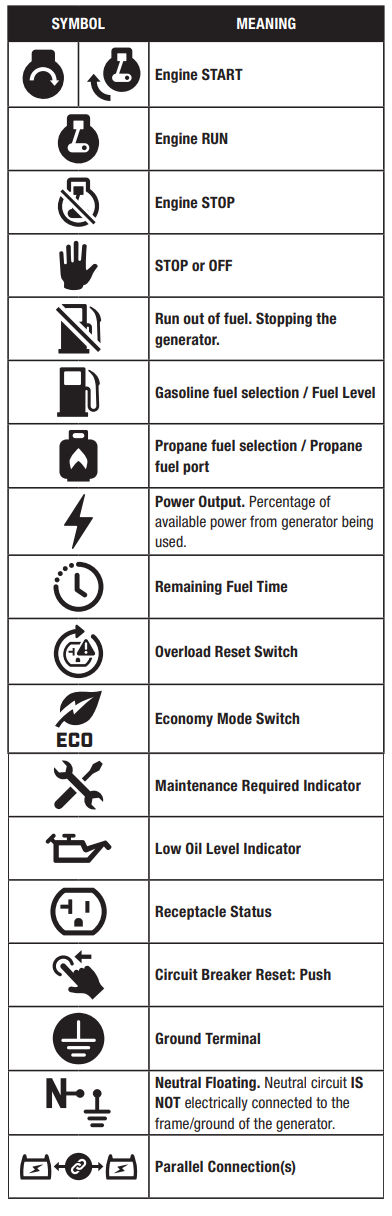
Operation Symbols
Some of the following symbols may be used on this product. Please study them and learn their meaning. Proper interpretation of these symbols will allow you to more safely operate the product.
Description
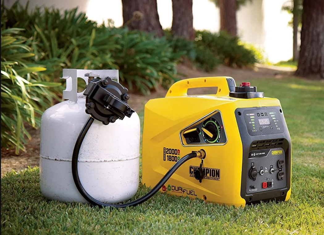
The Champion 2000W Dual Fuel Inverter Generator is designed with cutting-edge technology to deliver clean and stable power that is safe for sensitive electronics. This generator features an intelligent Auto-Switch that automatically switches between gasoline and propane based on fuel availability and load demand. The Eco-Mode feature helps conserve fuel and reduce noise by adjusting the engine speed according to the power required. The generator is also equipped with a low oil shut-off sensor that protects the engine from damage due to low oil levels. The compact and lightweight design of this generator makes it easy to transport and store, making it an ideal choice for outdoor enthusiasts and homeowners alike.
CONTROLS AND FEATURES
Read this operator’s manual before operating your generator. Familiarize yourself with the location and function of the controls and features. Save this manual for future reference.
Generator
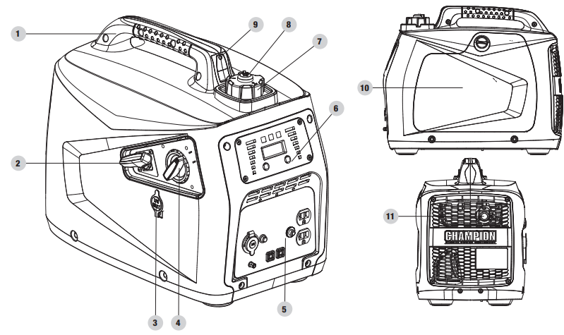
- Carrying Handle – Used to lift or carry the unit.
- Recoil Starter – Used to manually start the engine.
- LPG Inlet – Used to connect LPG fuel source to generator.
- EZ Start Dial – Used to start and stop the generator. When operating by propane, this switch will NOT stop the engine.
- Outlet Panel – See “Outlet Panel” section.
- Power Panel – See “Power Panel” section.
- Fuel Cap – Remove to add fuel.
- Fuel Lever Vent – Turn this valve to the “ON” position to supply air to the tank.
- Fuel Fill Assist LED – Push-button LED used to illuminate the gasoline fill area
- Maintenance Cover
- Muffler
Power Panel
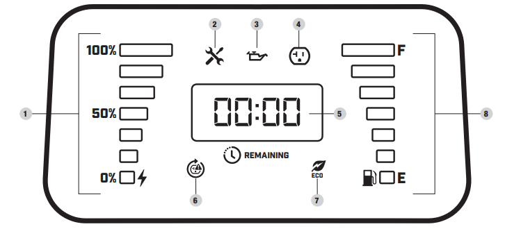
- Power Output – Percentage of available power from a generator being used.
- Maintenance Indicator
Off – No service required.
Yellow – Service required per Maintenance Schedule. - Low Oil Level Indicator
Off – Oil level OK.
Yellow – Oil level low. The unit will shut down or not start until the oil is at the required level. - Receptacle Status
Green – All systems are OK.
Red – Nearing overload but receptacle still has power. 4c. Flashing Red – Overload fault and receptacle has no power. - LED Display
Flashing Blue – Total run time (first 5 seconds after unit started).
Amber – Remaining fuel run time or “LPG” in LPG mode. - AC Overload Reset Button – Used to re-energize receptacles after overload fault and reset maintenance schedule.
OFF – Systems normal.
Yellow – Maintenance required.
Blinking Red – Overload fault. - Economy Mode Switch – Enables/disables automatic idle control.
OFF – Economy mode OFF.
Green – Economy mode ON. - Fuel Level Indicator – Amount of fuel remaining.
Outlet Panel
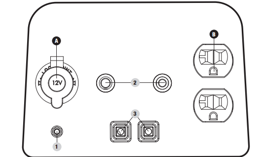
- Ground Terminal – Consult an electrician for local grounding regulations.
- Circuit Breakers (Push Reset) – Protect the generator against electrical overloads.
- Parallel Outlets – Used for parallel operation (parallel kit sold separately).
*Warning: Do not operate a device while it is plugged into the 12V DC outlet. Prolonged exposure to engine exhaust can cause serious injury or death. While charging a device do not place it on the exhaust side of the generator. Extreme heat caused by exhaust can damage the device, and cause a potential fire hazard.
Setup Guide
Setting up the Champion 2000W Dual Fuel Inverter Generator is easy. Here are the steps to follow:
- Choose your fuel: Fill the generator with either gasoline or propane.
- Add oil: Check the oil level and add oil if necessary. The generator comes with a pre-measured oil bottle.
- Turn on the fuel valve: Open the fuel valve to allow fuel to flow to the engine.
- Start the generator: Use the electric start button or the recoil start handle to start the generator.
- Adjust the engine speed: Use the Eco-Mode switch to adjust the engine speed according to your power requirements.
- Connect your devices: Plug your devices into the outlets and turn them on.
STORAGE
DANGER
Gasoline and gasoline vapors are highly flammable and extremely explosive.
Fire or explosion can cause severe burns or death. Only fill or drain fuel outdoors in a well-ventilated area. DO NOT pump gasoline directly into the generator. Use an approved container to transfer the fuel to the generator. Never use a gasoline container, gasoline tank, or any other fuel item that is damaged or appears damaged. DO NOT overfill the gasoline tank. Always keep fuel away from sparks, open flames, pilot lights, heat,, and other sources of ignition. DO NOT light or smoke cigarettes.
Short Term Storage (up to 1 year)
Gasoline in the gasoline tank has a maximum shelf life of up to 1 year with the addition of properly formulated fuel stabilizers and if stored in a cool, dry place. Gasoline in the carburetor, however, may gum up and clog the carburetor if it isn’t used or drained within 2-4 weeks.
- Be sure all appliances are disconnected from the generator.
- Add a properly formulated fuel stabilizer to the gasoline tank.
- Start the engine by following the directions in the “Starting the Engine: Gasoline” section.
- Run the generator for 10 minutes so the treated gasoline cycles through the fuel system and carburetor.
- Turn the EZ Start dial counterclockwise to the “RUN OUT OF FUEL” position.
- Let the engine run until fuel starvation has stopped the engine. This usually takes a few minutes.
- After the engine stops, turn the EZ Start dial counterclockwise to the “STOP” position.
- Allow the engine to cool.
- Remove the maintenance cover.
- Remove the spark plug and pour about a tablespoon of oil into the cylinder.
- SLOWLY pull the recoil to rotate the engine to distribute and lubricate the cylinder.
- Re-install the spark plug and spark plug wire.
- Re-install the maintenance cover.
- Clean the generator according to Cleaning the Generator.
- Store the generator in a cool, dry place out of direct sunlight. Long Term Storage (more than 1 year)
For storage over 1 year, the gasoline tank and carburetor must be completely drained of gasoline.
- Be sure all appliances are disconnected from the generator.
- Place the inverter on blocks to allow appropriate gasoline container or pan to slide under inverter.
- Remove the maintenance cover.
- Turn the EZ Start dial to the RUN position for gasoline.
- Using a Phillips screwdriver, rotate drain screw counterclockwise (3) full turns. Gasoline will drain through clear tubing out underneath the inverter. Make sure draining gasoline empties into an appropriate container.
- When gasoline stops flowing from the clear tube, rotate drain screw clockwise until tight. Properly dispose of the drained gasoline according to local regulations or guidelines.
- Turn the EZ Start dial to the STOP position.
- Follow steps 8-12 according to Short Term Storage.
Removing from Storage
If the generator has been improperly stored for a long period of time with gasoline in the gasoline tank and/or carburetor, all fuel must be drained and the carburetor must be thoroughly cleaned. This process involves technically advanced tasks. If the gasoline tank and carburetor were properly emptied of all gasoline prior to the generator being stored, follow the below steps when removing from storage.
- Be sure the EZ Start dial is in the STOP position.
- Add gasoline to the generator according to Add Fuel: Gasoline.
- Move the EZ Start dial to the START position.
- After 5 minutes check the carburetor and air filter areas for any leaking gasoline. If any leaks are found, the carburetor will need to be disassembled and cleaned or replaced. If no gasoline leaks are found, turn the EZ Start dial to the “STOP” position.
- Check engine oil level and add clean, fresh oil if needed. See Oil Specifications for proper oil type.
- Check and clear air filter of any obstructions such as bugs or cobwebs. If necessary, clean air filter according to Cleaning the Air Filter.
- Start the generator according to Starting the Engine.
DANGER
- Generator exhaust contains odorless and colorless carbon monoxide gas.
- To avoid accidental or unintended ignition of your generator during periods of storage, the following precautions should be followed:
- When storing the generator make sure the EZ Start dial is set to the “OFF” position.
TROUBLESHOOTING
Problem | Cause | Solution |
Generator will not start. | No fuel. | Add fuel. |
Faulty spark plug. | Replace spark plug. | |
Unit loaded during start up. | Remove load from unit. | |
Low oil level. | Fill crankcase to the proper level. | |
Place generator on a flat, level surface. | ||
Generator will not start; Generator starts but runs roughly. | Choke in the wrong position. | Adjust choke. |
Spark plug wire loose. | Attach wire to spark plug. | |
Generator shuts down during operation. | Out of fuel. | Fill fueltank. |
Low oil level. | Fill crankcase to the proper level. Place generator on a flat, level surface. | |
Overload condition | Remove load, press reset button | |
Overheat condition | Let generator cool down | |
Generator cannot supply enough power or overheating. | Generator is overloaded. | Review load and adjust. See “Connecting Electrical Loads.” |
Insufficient ventilation. | Check for airrestriction. Move to a well ventilated area. | |
No AC output. | Cable not properly connected. | Check all connections. |
Connected device is defective. | Replace defective device. | |
Circuit breaker is open. | Reset circuit breaker | |
Loose wiring. | Inspect and tighten wiring connections. | |
Other. | Contact the help line. | |
Generator gallops. | Engine governor defective. | Contact the help line. |
Repeated circuit breaker tripping. | Overload. | Review load and adjust. See "Connecting Electrical Loads." |
Faulty cords or device. | Check for damaged, bare or frayedwires. Replace defective device. |
WARRANTY
CHAMPION POWER EQUIPMENT 3 YEAR LIMITED WARRANTY
Warranty Qualifications
To register your product for warranty and FREE lifetime call center technical support please visit: https://www.championpowerequipment.com/register
Pros & Cons
- Pros:
- Dual fuel capability
- Quiet operation
- Fuel efficient Eco-Mode
- Clean and stable power
- Easy to use and transport
- Cons:
Customer Reviews
"I love this generator! It's perfect for camping and tailgating, and I love that I can use either gasoline or propane. The power is clean and stable, and the generator is super quiet. I would highly recommend this generator to anyone looking for a reliable and portable power source." - John M.
"I was a bit skeptical about the dual fuel capability, but this generator has exceeded my expectations. I've used it for power outages and camping trips, and it's worked flawlessly every time. The setup is easy, and the generator is lightweight and portable. I would definitely recommend this generator to anyone in the market for a reliable and versatile power source." - Mary K.
"I purchased this generator for emergency power outages, and it's been a lifesaver. The dual fuel capability is a game-changer, and the generator is surprisingly quiet. I've also used it for camping and tailgating, and it's been a great addition to my gear. Overall, I'm very impressed with this generator and would highly recommend it to anyone looking for a reliable and versatile power source." - Michael L.
Faqs
What kinds of fuel does the Champion work with?
How do I go from using gasoline to using propane?
How many watts does this generator need to start up and run?
Is it okay to use the Champion 2000W Dual Fuel Inverter Generator inside?
What do I do to turn on the generator?
Does the generator turn off when the oil level gets too low?
For how long does the Dual Fuel Inverter Generator come with a warranty?
How do I keep the engine in good shape?
Is it okay to use the Champion 2000W Dual Fuel Inverter Generator inside?
What kind of oil does the engine need?
Leave a Comment