How to Assemble: Dji A2 Flight control system User Manual
Content
DJI A2 Flight control system Introduction
The DJI A2 Multi-Rotor stabilization controller is a complete flight system for various multi-rotor platforms for commercial and industrial aerial photography. Based on the technology and design philosophy of DJI’s Ace series of high-performance controllers, the A2 offers you a brand new flight experience. Its flight mode provides a seamless transition for current Ace One, WKM AP professionals. A2 features includes:
- Integrated with high-precision sensor components and a high-performance GPS Receiver.
- Utilizes high quality components precisely calibrated with temperature compensation in all gyros and sensors, industry renowned flight algorithm in autopilot and UAV field.
- Designed with built-in vibration absorption, no extra mount frame or vibration absorption pad is required.
- Provide high precision control and high performance handling experience.
- Based on the DESST technology, it has a built-in 16-channel Receiver, and supports DSM2 satellite receiver.
- Optional DJI D-BUS Adapter can be used with a traditional Receiver.
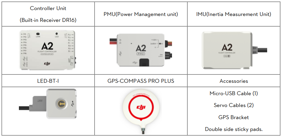
In the Box
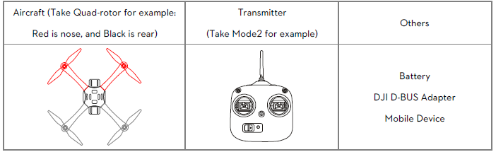
Equipment Prepared by Users
Detailed Specifications
The DJI A2 Flight Control System features a built-in IMU and barometer for precise hovering and flight stability. It has a maximum flight speed of 58 mph (93 km/h) and a maximum flight altitude of 16,404 feet (5,000 meters). It supports a wide range of GPS satellites for accurate positioning and has a built-in DJI Lightbridge system for long-range transmission.
System Introduction
The A2 flight control system uses the Controller Unit at its core, which is connected with the IMU, GPS-COMPASS PRO PLUS、LED-BT-I、PMU and ESCs to complete the system. The system can achieve the height-lock and position-lock functions by using the IMU and the GPS, to control the aircraft.
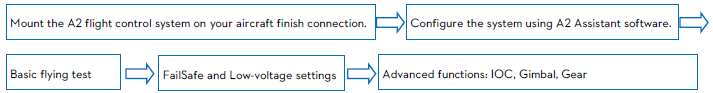
Please carry out the following procedures to finish assembly, configuration and flight-testing.
General Symbol
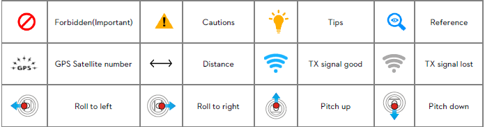
LED Symbol
| N=1 | N=2 | N=3 | N=4 | N=6 | N=20 | N=∝ |
Meaning |
One Blink |
Two Blinks |
Three Blinks |
Four Blinks |
Six Blinks |
Twenty Blinks | Continuous
Blinks |
Example: ![]() (3) means three Red blinks.
(3) means three Red blinks.
![]() (∝)LED blinks yellow and green alternatively.
(∝)LED blinks yellow and green alternatively.
 (N) | N=∝ |
Meaning | Continuous Solid on |
Example: ![]() (∝) means Continuous Blue Solid on.
(∝) means Continuous Blue Solid on.
Assembly and Configuration
For hardware installation, software configuration and compass calibration please adhere to the following sections.
Hardware Installation and Connection
- Please adhere to “1.1.1 Mixer Type Supported” to choose a mixer type and assemble your aircraft.
- Please adhere to both “1.1.2 Hardware Connection Diagram” and “1.1.3 Important for Assembly and Connection” to install and connect all units on your aircraft.
Mixer Type Supported
The following Mixer Types are supported.

WARNING: The direction of the arrow in diagram indicates the rotation direction of the motor/propeller. For coaxial propellers: Blue propeller is at TOP; Red propeller is at Bottom. Otherwise all propellers are at top.
Hardware Connection Diagram
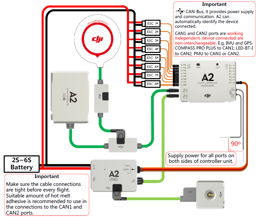
Important for Assembly and Connection
This section describes all device port functions, assembly requirements, connection requirements and tips during usage. Also the linking procedures between the built-in Receiver DR16 and your Transmitter. Please read all information below carefully, especially if you are a first time user.
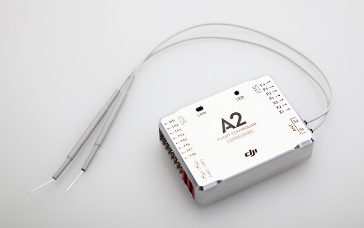
Controller Unit
The Controller Unit is the core component of the A2 flight control system:
- M1~M8 are used to connect to the ESCs of the aircraft.
- The built-in Receiver DR16 is based on DJI DESST technology, which can be used with the Futaba FASST series and DJI DESST series Transmitter.
- CAN1 and CAN2 ports are working independently and should connect to different modules.
- 4 independent and configurable outputs.
- It is compatible with the external Receiver, e.g. DSM2 satellite Receiver.
- Use the optional DJI DBUS Adapter to support the traditional receiver.
Description
The DJI A2 Flight Control System is a compact and easy-to-use flight control solution that offers professional-grade features and performance. It supports various flight modes, including GPS, Attitude, and Manual, allowing users to choose the mode that best suits their needs. The built-in DJI Lightbridge system enables long-range transmission, making it ideal for aerial photography and industrial applications.
Basic flying
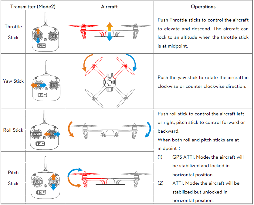
Control Mode Instruction
The aircraft performs differently when using different control modes. Please read the following table to know the different control modes, which may help you to achieve a more involved flight experience.
Control Mode | GPS ATTI. Mode
| ATTI. Mode | Manual Mode |
Command Linearity |
YES | ||
Yaw | Control the aircraft to rotate in clockwise and counter clockwise direction. Maximum rudder angular velocity 150°/s | ||
Roll and Pitch | Aircraft attitude control; Mid pointof stick is for 0˚ attitude, and its endpoint is 35˚. | Max-angular velocity is 150°/s. No attitude angle limit. | |
Throttle | Aircraft height control. Maintain the altitude best above 1 meter fromground when the throttle stick is in mid position. | No altitude locking when the throttle stick is in mid position. | |
All Sticks Released | Lock position if GPS signal is adequate. | Only attitude stabilizing. No position locking. |
Keep original attitude. |
GPS Lost | Once GPS signal lost the flight control system will enter ATTI. Mode automatically. Return to GPS ATT1. Mode after GPSsignal has recovered for 2 seconds. |
--- |
--- |
IOC Supported | CL/HL/POI/BTM | CL | None |
Assign a 3-position switch of the transmitter as the control mode switch. The position-1 is defaulted as “GPS ATTI. Mode” and the position-2 is “ATTI. Mode”. The position-3 can be set as “Manual Mode” or “ATTI. Mode” in A2 assistant software.
Control Mode Switch |
|
|
| |
Configurable Control Mode |
GPS ATTI. Mode |
ATTI. Mode * |
ATTI. Mode * |
Manual Mode |
FailSafe Protection | The flight control systemwill enter FailSafe Mode if the Transmitter signalis lost and nomatter if Transmitter signal recovers or not, system will not exit FailSafe mode automatically. | The flight control system will enter FailSafe Mode if the Transmitter signal is lost and the systemwillexit FailSafe once the signal recovers. | ||


GPS Involved | YES | NO | |
Low-voltage Protection | LED alertwith Descending or Go Home & Landing precautions |
Only LED alert | |
Environment recommended | Open flying field; Good GPSsignal | Narrow Space; GPS signal bad |
Regain control in emergency |
The difference between ATTI. Mode of position-2 and ATTI. Mode of position-3 is that they are working differently in protection situations.
Flying Environment Requirements
WARNING
- Before use of the product, please accept some flight training (Using a simulator to practice flying, getting instruction from a professional person, etc.).
- DO NOT fly in bad weather, such as rain or wind (more than moderate breeze) or fog.
- The flying field should be open without tall buildings or other obstacles; the buildings of steel structure will interfere with the compass.
- Keep the aircraft away from obstacles, crowds, power lines, trees, lakes and rivers etc.
- Try to avoid interference between the remote control Transmitter and other wireless equipment.(No base station or cell tower around)
- The flight control system can’t work at the South Pole and the North Pole.
- All parts must be kept out of the reach of children to avoid CHOKE HAZARD; if a child accidentally swallows any part you should immediately seek medical assistance.
Check List before Flying
Double-check the following list, otherwise, if any one of the following items is wrong it may lead to flight accident.
CAUTION
- All parts are in good condition, no ageing or damaged components
- Motor rotating direction
- Propeller mounting direction
- Mixer Type set in assistant software
- IMU and GPS-COMPASS PRO PLUS mounting direction
- Transmitter channel mapping and sticks movement direction correct
- Compass calibration
- ESC connection
- IMU and GPS-COMPASS PRO PLUS firmly mounted
In addition, check the following items to make sure the system can work.
WARNING
- The Transmitter battery is fully charged.
- The aircraft battery is fully charged.
- Do not overload the aircraft.
Power on and Check
Control mode LED indicator
Control Mode LED indicator | |||
ControlMode Switch |
|
|
|
LED |
|
| No LED indicator |
Set | Put the Control Mode switchto GPS position for basic flyingtest. Note: whenthe GPS signalLED indicator is bad or worst ( | ||
GPS signal LED indicator
GPS signal indication blinks after every Control mode indication. We suggest flying when GPS satellites are more than 5.
GPS signalLED indicator | |||
Worst ( | Bad ( | Well ( | Best ( |
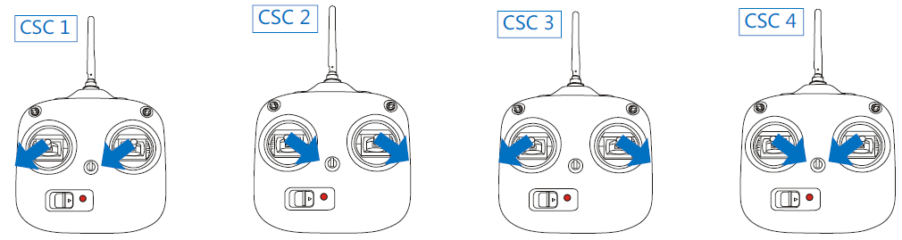
Start Motors Methods
CSC (Combination sticks commands) is used to start motors instead of just pushing the throttle stick. One of the following methods can be used to start/stop motors.
Under the conditions stated below, the motors will stop in ATTI. Mode/GPS ATTI. Mode:
- The throttle sticks is under 10% for more than 3secs after motors start.
- The throttle sticks is under 10% for more than 3secs after landing.
- The throttle sticks is under 10% for more than 3secs and the inclined angle of aircraft exceeds 70°。
If motors fail to start, please refer to the following list for trouble shooting.
- The Controller Unit fails to obtain the firmware version of IMU and GPS, please check the connection or upgrade the IMU and GPS.
- The firmware version of IMU and Controller Unit is mismatched; please upgrade the firmware of IMU or Controller Unit.
- The firmware version of GPS and Controller Unit is mismatched; please upgrade the firmware of GPS or Controller Unit.
- The transmitter calibration has exited abnormally, please recalibrate.
- The transmitter calibration results with big bias, please recalibrate.
- The transmitter calibration results with big mid point bias, please recalibrate.
- Incorrect channel mappings, please make sure the basic channels A/E/T/R/U are mapped correctly
- Invalid SN or SN error; please contact your dealer or DJI custom service.
- The Controller Unit is locked, please unlock the Controller Unit and reconfigure all the parameters in the Assistant software.
- IMU disconnected, please check the connection.
- Compass data abnormal, please eliminate magnetic interference and recalibrate the compass.
- When Flight limit function is enabled, if the aircraft fly out of the max-radius in ATTI. mode and the motors are stalling, the motors will fail to spool up in GPS ATTI. mode cause the Flight limit function works.
- The attitude status is bad and the LED indicator blinks white, the motors will fail to spool up
- The Transmitter disconnected, the motors will fail to spool up.
- The A2 flight control system is connecting and communicating with the Assistant software, the motors will fail to spool up.
Basic Flying Test
Carry out the following procedures to complete the basic flight test.
1. Waitthe GPS signal to be well | LED |
Place the aircraft away from you and others at least 3 meters and wait the |
|
2. Start motorsand takeoff aircraft. | LED |
Execute CSC to startmotors; all sticksback to midpoint as soon as motors start,then push the throttle stick to take off the aircraft, meanwhile the home pointis recorded. NOTE: 36secs after poweron; 10secs after position as home point at the firsttime the throttle stick is raised |
|
After the home pointis recorded successfully and the distance from aircraft is lessthan 8m, LED indicatorwill blink 5 violet continually. Note: only when GPS signal is good (no Red LED) LED indicator will blink 5 violet continually. |
|
Operate sticks to control the flying attitude of the aircraft during flight
4.Hover |
In GPS ATTI. Mode,the aircraft will hover when the throttle/yaw/roll/pitch sticks are all released at mid-point. |
5.Landing |
Use the throttle stick to control the landing speed, try to land youraircraft gently to avoid shock or crash. |
Please refer to the next section “Protection Functions Setting” to take precautions.
- Low voltage alert: yellow quick flashes or red quick flashes.
- FailSafe: LED indicator blinks blue.
Moreover, you may come across the following abnormal situation, please carry out the operation below. - Compass data is abnormal; the LED blinks yellow and green alternatively. Please re-calibrate the Compass.
- IMU data is abnormal, the LED blinks four green. Please contact your dealer.
PMU connection status detection:
- If detected before takeoff, the motors will not start and takeoff is inhibited. The LED module will continuously flash red four times. To resume normal flight, ensure that the PMU is connected correctly.
- If detected during flight, the LED module will continuously flash red four times, at which point you should land the aircraft and re-connect the PMU to resume the battery voltage readings and low voltage protection.
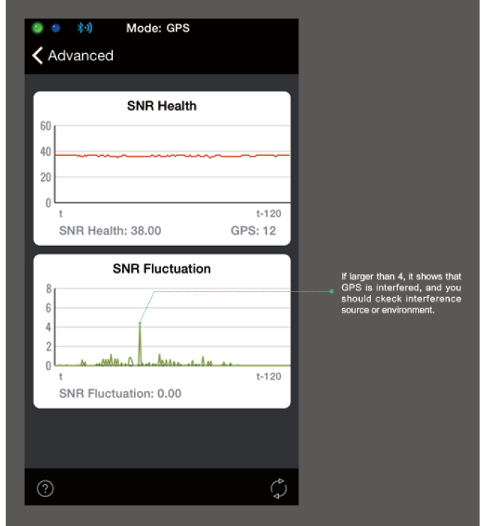
GPS SNR Functions Description
The DJI A2 Assistant (version 1.1.22) and iPad ground station (version 1.4.62) have recently added “SNR Health” and “SNR Fluctuation” index monitors for GPS signals. Users can monitor GPS signal quality, ensuring they have strong and stable signals for better flight performance. By referring to these two values, the user will be empowered to find the best locations for take-off and flight, while also detecting areas that might interfere with GPS signals.
The SNR interface provides you with “SNR Health” and “SNR Fluctuation” index monitors whose values change according to aircraft maneuvers and environmental interference.
- The “SNR Health Index” shows the GPS signal strength captured by the GPS receiver. A larger number indicates a stronger GPS signal. We highly recommend pilots only take off when the SNR health value is greater than 36.
The “SNR Fluctuation Index” shows the overall stability of the craft’s current GPS signal. A smaller number means that the signals will fluctuate less and provide a more stable GPS signal overall.
A2 Receiver Type Description
For different types of receivers, displays on the A2 Assistant software will be different. For PPM receivers with Failsafe, the display is as below:
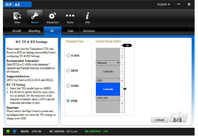
For the other receivers, the display is as below:
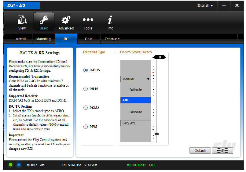
For example, when used with DJI Lightbridge, you will see the second display after disconnecting the remote controller and Lightbridge. At this time, the A2 LED will blink blue and the aircraft will enter Failsafe.
Channel Mapping Instructions for PC Assistant Software
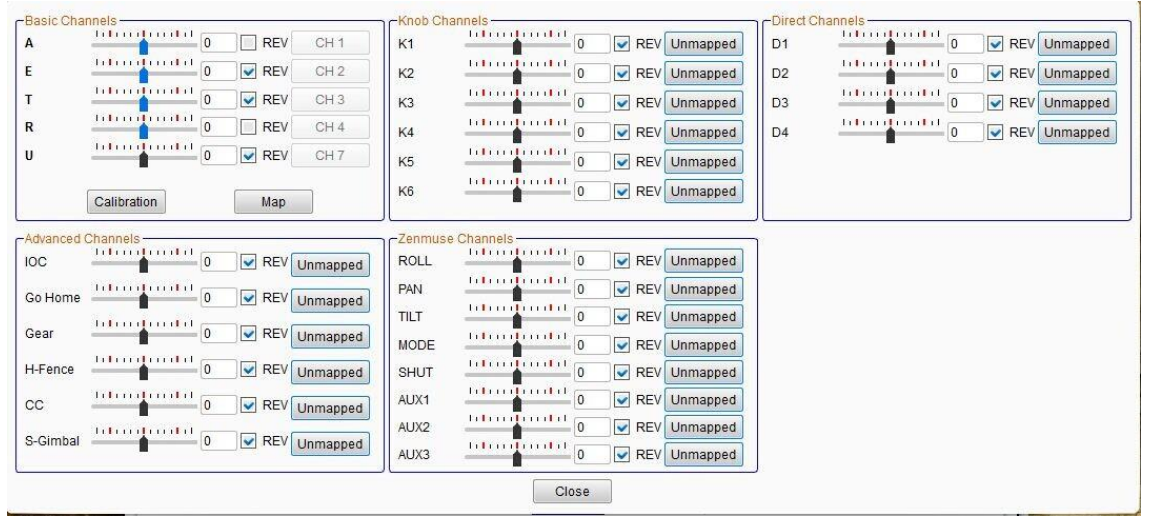
Basic Channels | Default Settings | Usage Descriptions |
A | Roll Control of the Controller Unit, mapped to the Channel 1 of Receiver |
During Assistant Software usage, please click the “Calibration” button, to calibrate the Transmitter sticks travel.During calibrating, make sure to operate strictly following the prompts; otherwise may lead to calibration failure. Click the “Map” button, then you can re-do mapping for A/E/T/R/U. |
E | Pitch Control of the Controller Unit, mapped to the Channel2 of Receiver | |
T | Throttle Control of the Controller Unit, mapped to the Channel3 of Receiver | |
R | Yaw Control of the Controller Unit, mapped to the Channel4 of Receiver | |
U | Control Mode Switchof the Controller Unit, mapped to the Channel7 of Receiver | |
Knob Channels | Default Settings | Usage Descriptions |
K1~K6 | Remote Gains Adjustment of the Controller Unit, unmapped. | Click “Unmapped” button to map K1~K6to the channels of Receiver. |
Direct Channels | Default Settings | Usage Descriptions |
D1~D4 | Direct Channels (The corresponding ports are F1~F4 on the Controller Unit) of Controller Unit, unmapped. | Click “Unmapped” button to map D1~D4 to the Receiver channels. If you enable the Gimbal functions in Assistant Software, then the F3/F2 are usedfor gimbal control; even D3/D2 are mapped to channels of Receiver, and the signals from the mappedReceiver |
channels will be ignored. You can use F4 for switching the video channel of iOSD Mark II, then map D4 to a Receiver channel. | ||
Advanced Channels | Default Settings | Usage Descriptions |
IOC | IOC function of the Controller Unit, unmapped. | Click “Unmapped” buttonto map IOC to a Receiver channel. It is recommended to use a 3-position switch channel. |
Go Home | One-Key Go Home function of the Controller Unit, unmapped. | Click “Unmapped” button to map Go Home to the Receiver channel. It is recommended to use a 2-position switch channel. |
Gear | Intelligent Gear function of the Controller Unit, unmapped. | If you enable the Gear function in Assistant Software, then the F1 is used for the gear control of S800 EVO landing. |
H-Fence(Home Fence) | Home Fence function unmapped | Click “Unmapped” button to map Home Fence onto the Receiver channel. It is recommended to use a 2-position switch channel. |
CC (Cruise Control) | Cruise Control function unmapped | Click “Unmapped” button to map Cruise Control to the Receiver channel. It is recommended to use a 3-position switch channel. |
S-Gimbal | Ground station servogimbal function unmapped | Click “Unmapped” button to map Ground station servo gimbal to the Receiver channel.It is recommended to use a 3-position switch channel. |
Zenmuse Channels | Default Settings | Usage Descriptions |
ROLL | ROLL channel unmapped | Click “Unmapped” button to map ROLL to the Receiver channel. It is recommended to use a level switch channel. |
TILT | TILT channel unmapped | Click “Unmapped” buttonto map TILTto the Receiver channel. It is recommended to use a level switch channel. |
PAN | PAN channel unmapped | Click “Unmapped” buttonto map PAN to the Receiver channel. It is recommended to use a level switch channel. |
MODE | MODE channel unmapped | Click “Unmapped” buttonto map MODE to the Receiver channel. It is recommended to use a 3-position switchchannel. |
SHUT | SHUT channel unmapped | Click “Unmapped” button to map SHUT to the Receiver channel. It is recommended to use a 2-Position switch withspring back function. |
AUX1 | AUX1 channel unmapped | Click “Unmapped” button to map AUX1 to the Receiver channel. It is recommended to use a 3-position switch channel. |
AUX2 | AUX2 channel unmapped | Click “Unmapped” button to map AUX2 to the Receiver channel. It is recommended to use a 2-position switch channel. |
AUX3 | AUX3channel unmapped | Click “Unmapped” buttonto map AUX3 to the Receiver channel. It is recommended to use a 2-position switch channel. |
Recommended Mapping for Futaba RC (Mode 2, A2 V2.4 or below)
Controller Unit Channel | Receiver Channel | Recommended Transmitter Switch |
A | Channe 1 (AIL) | Joystick J1 |
E | Channe 2 (ELE) | Joystick J2 |
T | Channe 3 (THR) | Joystick J3 |
R | Channe 4 (RUD) | Joystick J4 |
U | Channe 7 (AUX5) | 3-Position switch, e.g. SG |
K1~K6 | Channe 5 (GEAR) | Knob switch, e.g. LD, RD |
Pitch | Channe 6 (Vpp)* | Knob switch, e.g. LD, RD |
D1/D3/D2 | ---- | ---- |
D4 | Channe 9 (AUX1) | 2-Position switch, e.g. SF |
IOC | Channe 10 (AUX2) | 3-Position switch, e.g. SG |
Go Home | Channe 11 (AUX3) | 2-Position switch with spring back function, e.g. SH |
Gear | Channe 8 (AUX4) | 2-Position switch, e.g. SF |
H3-2D | Channe 12(AUX5)* | Knob switch, e.g. LD、RD |
H-Fence | Channe 6 (Vpp)* | 2-Position switch, e.g. SF |
CC | Channe 12(AUX5)* | 3-Position switch, e.g. SB |
Recommended Mapping for Futaba RC (Mode 2, A2 V2.5 and Futaba below V5.0)
Controller Unit Channel | Receiver Channel | Recommended Transmitter Switch |
A | Channe 1 (AIL) | Joystick J1 |
E | Channe 2 (ELE) | Joystick J2 |
T | Channe 3 (THR) | Joystick J3 |
R | Channe 4 (RUD) | Joystick J4 |
U | Channe 7 (AUX5) | 3-Position switch, e.g. SG |
IOC/CC | Channe 8 (AUX4) | 3-Position switch, e.g. SA |
Gear | Channe 9 (AUX6) | 2-Position switch, e.g. SF |
PAN | Channe 5 (GEAR) | Level switch, e.g. LS、RS |
TILT | Channe 6 (Vpp) | Level switch, e.g. LS、RS |
MODE | Channe 10 (AUX1) | 3-Position switch, e.g. SC |
Photo | Channe 11 (AUX2) | 2-Position switch with spring back function, e.g. SH |
Video | Channe 12 (AUX3) | 3-Position switch, e.g. SG |
Recommended Mapping for Futaba RC (Mode 2, A2 V2.5 and Futaba V5.0)
Controller Unit Channel | Receiver Channel | Recommended Transmitter Switch |
A | Channe 1 (AIL) | Joystick J1 |
E | Channe 2 (ELE) | Joystick J2 |
T | Channe 3 (THR) | Joystick J3 |
R | Channe 4 (RUD) | Joystick J4 |
U | Channe 7 (AUX5) | 3-Position switch, e.g. SG |
IOC | Channe 8 (AUX4) | 3-Position switch, e.g. SA |
CC | Channe 9 (AUX6) | 2-Position switch, e.g. SF |
Gear | DG1 | 2-Position switch, e.g. SF |
ROLL | Channe 10 (AUX1) | Knob switch, e.g. LD、RD |
PAN | Channe 5 (GEAR) | Level switch, e.g. LS、RS |
TILT | Channe 6 (Vpp) | Level switch, e.g. LS、RS |
MODE | Channe 11 (AUX2) | 3-Position switch, e.g. SC |
Photo | DG2 | 2-Position switch with spring back function, e.g. SH |
Video | Channe 12 (AUX3) | 3-Position switch, e.g. SG |
Recommended Mapping for DJI NDJ6 RC (A2 V2.5)
Controller Unit Channel | Receiver Channel | Recommended Transmitter Switch |
A | A | Master remote control J1 |
E | E | Master remote control J2 |
T | T | Master remote control J3 |
R | R | Master remote control J4 |
U | U | Master remote control S1 |
Gear | X2 | Master remote control S2 |
ROLL | A | Slave remote control J1 |
PAN | E | Slave remote control J2 |
TILT | R | Slave remote control J4 |
MODE | U | Slave remote control S1 |
Photo | X1 | Slave remote control LD |
Video | X2 | Slave remote control S2 |
Note that these settings should be configured according to your requirements. Follow the steps below to check if the channels are working properly:
- Run the A2 Assistant and go to the Channel Mapping page.
- Move the Master remote controller’s sticks and switches to ensure they are working properly on the Channel Mapping page.
Note: For the H3-3D gimbal, set a 2-position switch with spring back function for the TILT channel and a 2-position switch for the MODE channel.
Settings of gain values for Your Reference
To set the value of basic gain and attitude gain you can refer to the following diagram. These values are only for reference and may vary in practice.
Aircraft | Configuration Information | Basic | Attitude | ||||||||
Motor | ESC | Propeller | Battery | Weight | Pitch | Roll | Yaw | Pitch | Roll | Vertical | |
F450 | DJI-2212 | DJI-30A | DJI-8 Inch | 3S-2200 | 890 g | 150 | 150 | 135 | 150 | 150 | 140 |
F550 | DJI-2212 | DJI-30A | DJI-8 Inch | 4S-3300 | 1530 g | 170 | 170 | 150 | 160 | 160 | 150 |
S800 EVO/Z15 | DJI-4114 | DJI-40A | DJI-15Inch | 6S-15000 | 7000g | 140 | 140 | 130 | 140 | 140 | 130 |
S1000/5D gimbal/
5D camera |
DJI-4114 |
DJI-40A |
DJI-15Inch |
6S-15000 |
9200g |
120 |
120 |
120 |
170 |
170 |
120 |
S1000/5D gimbal/
5D camera |
DJI-4114 |
DJI-40A |
DJI-15Inch |
6S-15000 |
9300g |
120 |
120 |
120 |
170 |
170 |
120 |
The Transmitter setup of FUTABA
Please configure the Frequency item on your Transmitter adhere to the table below. (The names of FASST modes here are based to the Transmitter FUTABA T8FG, please ensure to select the most similar mode as the names differs for different Transmitters)
Transmitter type | AREA | FASST |
FUTABA 18MZ | Default | FASST-MULTI\FASST-7CH |
FUTABA 14MZ with TM-14 | Default | MULT\7CH |
FUTABA 14SG | FRANCE\GENERAL | FASST-MULTI\FASST-7CH |
FUTABA 12Z 2.4G FASST with TM-14 | Default | MULT\7CH |
FUTABA 12FG 2.4G FASST with TM-14 | Default | MULT\7CH |
FUTABA 10CG or 10C with TM-10 | Default | 7CH |
FUTABA 9C SUPER with TM-7 or TM-8 | Default | 7CH |
FUTABA 8FG SUPER | FRANCE\GENERAL | MLT2\MULT\7CH |
FUTABA 8FG | FRANCE\GENERAL | MULT/7CH |
FUTABA 7C 2.4G | Default | Default |
FUTABA 6EX FASST | Default | Default |
Troubleshooting
- If you encounter any issues with your DJI A2 Flight Control System, there are a few common solutions to try.
- First, check to ensure that all cables and connections are securely fastened.
- If the issue persists, try resetting the system to its factory settings.
- If you are still experiencing problems, contact DJI's customer support for further assistance.
Pros & Cons
Pros
- Professional-grade features and performance
- Supports a wide range of flight modes
- Long-range transmission capabilities
- Easy to use and set up
Cons
- Expensive compared to other flight control systems
- May be overkill for casual users
Customer Reviews
Overall, customers have been impressed with the performance and features of the DJI A2 Flight Control System. Many have praised its ease of use and long-range transmission capabilities, while others have noted its professional-grade features and performance. However, some have criticized its high price point, noting that it may be overkill for casual users.
Faqs
What is the Flight Control System of the DJI A2?
For what drones is the DJI A2 Flight Control System compatible?
Which characteristics make up the DJI A2 Flight Control System's core?
How do I upgrade the DJI A2 Flight Control System's firmware?
How can I adjust the DJI A2's compass?
Which sensors are built into the flight control system of the DJI A2?
Leave a Comment