Dometic Roof Top Unit Air Conditioner 641415.30X User Guide
Content
Introduction
The Dometic Roof Top Unit Air Conditioner 641415.30X is a high-performance cooling solution designed for recreational vehicles and trailers. With a powerful 15,000 BTU capacity, it efficiently cools spaces up to 400 square feet, ensuring comfort during hot summer days. The unit features a sleek, low-profile design that minimizes wind resistance and noise. Equipped with easy-to-use controls and a robust construction for durability, it’s perfect for any travel enthusiast. Priced at $1,199, this air conditioner is an essential addition for a comfortable RV experience.
Specifications
| Model No. | Nominal Capacity (BTU HR) | Cooling Electrical Rating | Compressor Rated Load Amps | Compressor Locked Rotor Amps | Fan Motor Rated Load Amps | Fan Motor Locked Rotor Amps | Refrigerant R-410A (Oz.) | Minimum Wire Size* | AC Circuit Protection | Minimum Generator Size |
|---|---|---|---|---|---|---|---|---|---|---|
| 641415.30X | 13,500 | 120 VAC 60Hz. 1PH | 12.5 | 61.0 | 3.5 | 10.0 | 17.5 | 12 AWG Copper | ***Installer Supplied | 3.5 KW / 5.0 KW |
- For wire length over 24 ft., consult the National Electric Code for proper sizing.
- Dometic Corporation gives GENERAL guidelines for generator requirements. These guidelines come from experiences people have had in actual applications. When sizing the generator, the total power usage of your recreational vehicle must be considered. Keep in mind generators lose power at high altitudes and from lack of maintenance.
- CIRCUIT PROTECTION: Time Delay Fuse or Circuit Breaker Required.
Roof Top Unit | ||||
Description | Model | UseWith Air Distribution Box | ||
3310742.XXX | Control | Indoor Temperature Sensor | ||
Air Conditioner | 641415 | Analog BoardBuilt In | N/A | |
641416 | Analog BoardBuilt In | N/A | ||
641515 | CCC BoardBuilt In | Optional 3106486.XXX | ||
641516 | CCC BoardBuilt In | Optional 3106486.XXX | ||
641715 | Digital BoardBuilt In | N/A | ||
641716 | Digital BoardBuilt In | N/A | ||
641815 | CCC 2 Board BuiltIn | Optional 3311931.XXX | ||
641816 | CCC 2 Board BuiltIn | Optional 3311931.XXX | ||
641915 | LCD BoardBuilt In | N/A | ||
641916 | LCD BoardBuilt In | N/A | ||
Air Conditioner W/Electric Heat | 641432 | Analog BoardBuilt In | N/A | |
641435 | Analog BoardBuilt In | N/A | ||
641535 | CCC BoardBuilt In | Optional 3106486.XXX | ||
641732 | Digital BoardBuilt In | N/A | ||
641735 | Digital BoardBuilt In | N/A | ||
641835 | CCC 2 Board BuiltIn | Optional 3311931.XXX | ||
641932 | LCD BoardBuilt In | N/A | ||
641935 | LCD BoardBuilt In | N/A | ||
Heat Pump | 651515 | CCC BoardBuilt In | Optional 3106486.XXX | |
651516 | CCC BoardBuilt In | Optional 3106486.XXX | ||
651815 | CCC 2 Board BuiltIn | Optional 3311931.XXX | ||
651816 | CCC 2 Board BuiltIn | Optional 3311931.XXX | ||
651915 | LCD BoardBuilt In | N/A | ||
651916 | LCD BoardBuilt In | N/A | ||
Note: Installation requires a #2 phillips screwdriver with 9/32" maximum diameter x 1-1/4" minimum length.
WARNING: This manual must be read and understood before installation, adjustment, service, or mainte-nance is performed. This unit must be installed by a qualified service technician. Modification of this product can be extremely hazard-ous and could result in personal injury or property damage.
IMPORTANT SAFETY INSTRUCTIONS
This manual has safety information and instruc-tions to help users eliminate or reduce the risk of accidents and injuries.
RECOGNIZE SAFETY INFORMATION
This is the safety alert symbol. It is used to alert you to personal injury hazards. Obey all safety messages that follow this symbol to avoid pos-sible injury or death.
UNDERSTAND SIGNAL WORDS
A signal word, when used with the safety alert symbol, will identify a safety hazard and its level of risk for personal injury. A signal word, without the safety alert symbol, will be used for property damage messages only.
WARNING indicates a hazard-ous situation which, if not avoided, could result in death or serious injury.
CAUTION, used with the safe-ty alert symbol, indicates a hazardous situation which, if not avoided, could result in minor or moderate injury.
NOTICE is used to address practices not related to personal injury.
WARNING Read and follow all safety information and instructions to avoid personal injury.
GENERAL INFORMATION
- Product features or specifications as described or il-lustrated are subject to change without notice.
- This air conditioner/heat pump (hereinafter referred to as the "unit") is designed for:
- Installation on a recreational vehicle during the time the vehicle is manufactured.
- Mounting on the roof of a recreational vehicle.
- Roof construction with rafters/joists on minimum of 16 inch centers.
- Minimum of 1.00 inch and maximum of 5.5 inches distance between roof to ceiling of recreational vehicle.
- The ability of the air conditioner to maintain the de-sired inside temperature depends on the heat gain of the RV.
Some preventative measures taken by the occupants of the RV can reduce the heat gain and improve the performance of the air conditioner. During extremely high outdoor temperatures, the heat gain of the ve-hicle may be reduced by:- Parking the RV in a shaded area
- Using window shades (blinds and/or curtains)
- Keeping windows and doors shut or minimizing usage
- Avoiding the use of heat producing appliances
Operation on High Fan/Cooling mode will give opti-mum or maximum efficiency in high humidity or high outside temperature.
Starting the air conditioner early in the morning and giving it a "head start" on the expected high outdoor ambient will greatly improve its ability to maintain the desired indoor temperature.
For a more permanent solution to a high heat gain, ac-cessories like Dometic outdoor patio and window awnings will reduce heat gain by removing the direct exposure to the sun. They also add a nice area to enjoy company dur-ing the cool of the evening.
- Condensation
Note: The manufacturer of this unit will not be responsible for damage caused by condensed moisture on ceilings or other surfaces. Air contains moisture and this moisture tends to condense on cold surfaces. When air enters the RV, condensed moisture may appear on the ceiling, win-dows, metal parts, etc. During normal operation this unit removes moisture from the air. Keeping doors and win-dows closed when this air conditioner is in operation will minimize condensed moisture on cold surfaces.
Description
The Dometic Roof Top Unit Air Conditioner 641415.30X is built with a focus on performance and durability. The unit features a sturdy construction that withstands harsh weather conditions and extreme temperatures. It includes a powerful compressor and fan motor that ensure efficient cooling even in hot climates. The air conditioner also comes with a digital thermostat and remote control, allowing for easy temperature adjustment from anywhere inside the RV.
The design of the unit is sleek and compact, making it ideal for installation on the roof of recreational vehicles without obstructing other roof-mounted accessories. It also features an easy-to-clean air filter to maintain optimal performance and indoor air quality.
INSTALLATION INSTRUCTIONS
Precautions
Warning: PERSONAL INJURY HAZARD. Failure to obey these installation instructions may cause seri-ous personal injury and/or property damage.
- Read installation and operating instructions carefully before attempting to start this unit installation.
- Dometic Corporation will not be liable for any damages or injury incurred due to failure in following these instructions.
- Installation MUST comply with the National Electrical Code ANSI/NFPA-70 and CSA Standard C22.1 (latest edition) and any State or Local Codes or regulations.
- Do NOT add any devices or accessories to this unit except those specifically authorized in writing by Dometic Corporation.
- This equipment MUST be serviced by qualified personnel and some states require these people to be licensed.
Choosing Proper Location For The Unit
This unit is specifically designed for installation on the roof of a recreational vehicle (RV). When determining your cooling requirements, the following should be considered:
- Size of RV;
- Window area (increases heat gain);
- Amount of insulation in walls and roof;
- Geographical location where the RV will be used;
- Personal comfort level required.
- For one unit installation: The unit should be mounted slightly forward of center (front to back) and centered from side to side.
- For two unit installations: Install one unit 1/3 and one unit 2/3's from front of RV and centered from side to side.
It is preferred that the unit be installed on a relatively flat and level roof section with the RV parked on a level sur-face, but up to a 8° tilt is acceptable. - After Location Has Been Selected
Check for obstructions in the area where unit will be installed. See FIG. 1.

- The roof must be designed to support 130 pounds when the RV is in motion. Normally a 200 lb. static load design will meet this require-ment.
NOTICE: PROPERTY DAMAGE HAZARD. It is the re-sponsibility of the installer of this system to ensure structural integrity of the RV roof. Never create a low spot on the roof where water will collect. Failure to obey this warn-ing may cause water damage to the product and the RV. Check inside the RV for air distribution box obstructions. (i.e. door openings, room divid-ers, curtains, ceiling fixtures, etc.) See FIG. 2.

Roof Preparation
- Opening Requirements
Before preparing the ceiling opening, the type of system options must be decided upon. Read all of the following instruc-tions before beginning the installation.
WARNING: SHOCK HAZARD. There may be electrical wiring between the roof and the ceiling. Dis-connect 120 VAC power supply and the posi-tive (+) 12 VDC terminal at the supply battery. Failure to obey this warning may cause death or severe personal injury. - Mark a 14-1/4" x 14-1/4" (±1/8") square on the roof and carefully cut the opening. The 14-1/4" x 14-1/4" (±1/8") opening is part of the return air system of the unit and MUST be finished in ac-cordance with ANSI A 119.2.
- Using the roof opening as a guide, cut the match-ing hole in the ceiling.
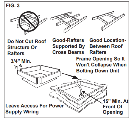
The opening created must be framed to provide adequate support and prevent air from being drawn from the roof cavity. Framing stock 3/4" thick or more must be used. Remember to pro-vide an entrance hole at the front of the opening for power supplies, indoor temperature sensor (if applicable), communication cable, and furnace wiring (if applicable). See FIG. 3.
WARNING: PROPERTY DAMAGE HAZARD. It is the re-sponsibility of the installer of this system to ensure structural integrity of the RV roof. Never create a low spot on the roof where water will collect. Failure to obey this warning may cause water damage to the product and the RV.
Wiring Requirements
- Route a copper, with ground, 120 VAC supply wire from the time delay fuse or circuit breaker box to the roof opening. The proper size wire can be determined from the chart on page 3.
- This supply wire must be located in the front portion of the 14-1/4" x 14-1/4" (±1/8") open-ing.
- The power MUST be on an appropriately sized separate time delay fuse or circuit breaker. The proper size protection can be determined from the chart on page 3.
- Make sure at least 15" of supply wire extends into the roof opening. This insures an easy connection at the junction box.
- Wiring MUST comply with National Electri-cal Code ANSI/NFPA-70 and CSA Standard C22.1 (latest edition) and any State or Local Codes or regulations.
- Protect the wire where it passes into the opening with approved method. See paragraph "d" above.
- Route a dedicated 12 VDC supply wire (18-22 AWG) from the RV's converter (filtered side) or battery to the roof opening.
Note: When a Comfort Control Center (hereinafter re-ferred to as CCC) thermostat is being installed with mul-tiple zones, this 12 VDC supply wire needs to be supplied to the unit designated zone 1 only.
Note: When a Comfort Control Center 2 (hereinafter referred to as CCC 2) thermostat is being installed with more than 2 zones, route a dedicated 12 VDC supply wire (18-22 AWG) to zone 1 and zone 3 roof opening.- This supply wire must be located in the front portion of the 14-1/4" x 14-1/4" (±1/8") open-ing.
- Make sure that at least 15" of supply wire ex-tends into the roof opening.
- Route an indoor temperature sensor (Optional) from the roof opening to the indoor temperature sensor location. The 2 pin connector end goes to the roof opening. See indoor temperature sensor installation instructions for proper sensor loca-tion.
- Thermostat Control Cable
- CCC, CCC 2 & Digital thermostat.
- Route a 4 conductor communication ca-ble from the 14-1/4" x 14-1/4" (±1/8") roof opening to the thermostat mounting loca-tion. Review section E "Choosing Ther-mostat Location" before routing com-munication cable. Choose the shortest most direct route. Make sure that at least 15" of wire extends into the roof opening and 6" extends from the wall at the thermo-stat mounting location.
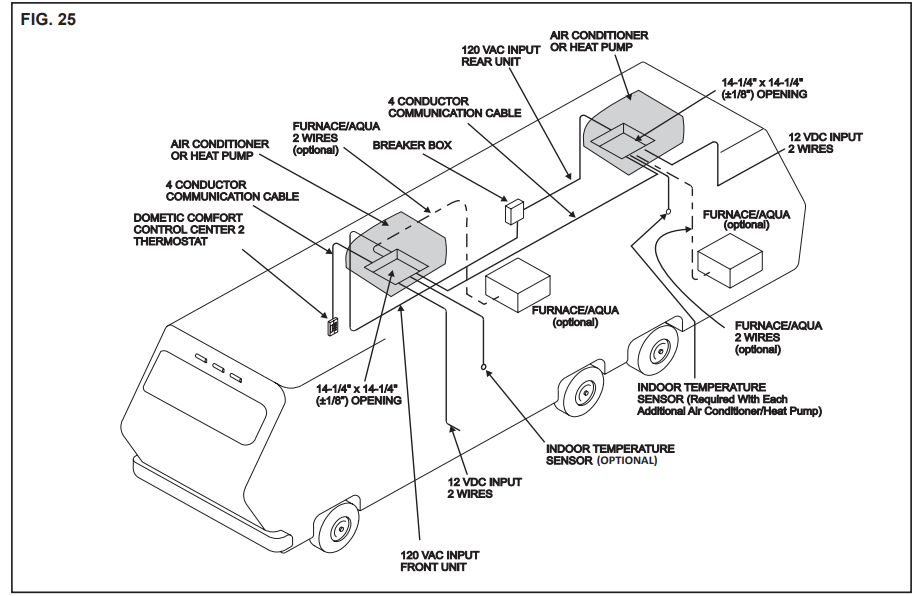
Important: When more than one unit is being in-stalled (additional zones) with the CCC and CCC 2 thermostat, an additional 4 conductor communica-tion cable must be routed to each additional unit 14-1/4" x 14-1/4" (±1/8") roof opening. Make sure at least 15" of wire extends into the roof opening. See FIG. 25.
- Route a 4 conductor communication ca-ble from the 14-1/4" x 14-1/4" (±1/8") roof opening to the thermostat mounting loca-tion. Review section E "Choosing Ther-mostat Location" before routing com-munication cable. Choose the shortest most direct route. Make sure that at least 15" of wire extends into the roof opening and 6" extends from the wall at the thermo-stat mounting location.
- Analog Thermostat
- Route a 7 conductor cable, 18 to 22 AWG, from the 14-1/4" x 14-1/4" (±1/8") to the thermostat mounting location. Review sec-tion E "Choosing Thermostat Location" before routing cable. Make sure 15" of the wire extends into the roof opening and 6" of wire extends from the wall at the ther-mostat mounting location.
- LCD Thermostat
- Route a 3 conductor cable, 18 to 22 AWG, from the 14-1/4" x 14-1/4" (±1/8") roof open-ing to the Single Zone LCD (hereinafter re-ferred to as SZLCD) thermostat mounting location. Review section E "Choosing Thermostat Location" before routing cable. Make sure that at least 15" of the wire extends into the roof opening and 6" extends from the wall at the thermostat mounting location.
- CCC, CCC 2 & Digital thermostat.
- If system includes a gas furnace, route two 18 gauge thermostat wires from the furnace to the roof opening of the unit that will control it. If more than one furnace is to be used, route the second set of thermostat wires to the second unit. Make sure that 6" of wire extends into the opening.
- Energy Management System (CCC and CCC 2 Only)
- If an Energy Management System (load shed feature) is to be used with the control, two wires must be routed to the roof opening of the zone to be managed. The signal required for this function is normally an open relay contact. When the EMS calls for the com-pressor to shut off, the relay contacts should close. Make sure at least 15" of the EMS wire extends into the roof opening.
- Automatic Generator Start Kit (CCC and CCC 2 Only)
- If an Automatic Generator Start (AGS) kit will be installed, an additional 4 conductor com-munication cable must be routed from the last unit to the location of the AGS kit. Follow AGS kit instructions for installation.
Choosing Thermostat Location
- CCC and CCC 2 (WITHOUT Indoor Temperature Sensor), Analog, Digital, and Single Zone LCD Thermostat.
The proper location of the thermostat is very im-portant to ensure that it will provide a comfort-able RV temperature. Observe the following rules when selecting a location.- Locate the thermostat 54" above the floor.
- Install the thermostat on a partition, not on an outside wall.
- NEVER expose the thermostat to direct heat from lamps, sun or other heat producing items.
- Avoid locations close to doors that lead out-side, windows or adjoining outside walls.
- Avoid locations close to supply registers and the air from them.
Note: On CCC and CCC 2 System installations WITH op-tional indoor temperature sensor, the thermostat may be mounted anywhere that is convenient in the RV. Try to avoid hard to reach and hard to see areas.
Thermostat, Indoor Temperature Sensor, And Thermostat Cable Installation
Note: A 2" hole in the wall is required at the CCC 2 ther-mostat location. A 3/8" hole in the wall is required at the CCC, Digital, Analog, and LCD thermostat location.
- CCC Thermostat.
The previously run communication cable (4 conductor telephone cable) must be termi-nated with two (2) RJ-11-6C4P telephone connectors. Refer to the crimp tool manu-facturer for crimping instructions. See FIGS. 4 & 5.

Important: RJ-11-6C4P connectors must be in-stalled as shown in FIGS. 4 & 5.
Carefully remove the base plate from the CCC thermostat. This may be accomplished by inserting a small screwdriver under the tab on the bottom edge of the front cover and gently prying. See FIG. 6

- Insert the control cable through the hole in the base plate and mount the plate to the wall with the two (2) screws provided.
- Install the control cable RJ-11-6C4P connec-tor into the back of the CCC thermostat and snap on the base plate.
- Optional Indoor Temperature Sensor
- Refer to the instructions provided with the indoor temperature sensor for details of installation.
- CCC 2 Thermostat.
- The previously run communication cable (4 conductor telephone cable) must be termi-nated with two (2) RJ-11-6C4P telephone connectors. Refer to the crimp tool manu-facturer for crimping instructions. See FIGS. 4 & 5.
Important: RJ-11-6C4P connectors must be in-stalled as shown in FIGS. 4 & 5. - Choose the shortest, most direct route from the 14-1/4" x 14-1/4" (±1/8") opening to the selected CCC 2 thermostat location. Leave 6" of cable extending through the wall.
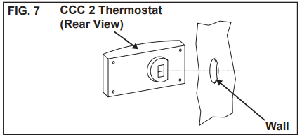
Route the communication cable through the 2" diameter hole in the wall required for the thermostat. See FIG. 7.
- Optional Indoor Temperature Sensor
- Refer to the instructions provided with the indoor temperature sensor for details of installation.
- CCC 2 Thermostat Installation
Carefully separate the thermostat base plate from the thermostat cover. Insert a small screw driver into the slot on bot-tom of thermostat and disengage the tab. See FIG. 8.

- Insert the 4 conductor communication cable through the hole in base plate. Align thermostat base plate with hole in wall. Make sure base plate is level and attach base plate to wall using the 4 sup-plied screws.
Insert the 4 conductor communication cable connector (RJ-11-6C4P) into the connector on the back of the thermostat. See FIG. 9.

- Align the thermostat with the back plate and snap into position.
- The previously run communication cable (4 conductor telephone cable) must be termi-nated with two (2) RJ-11-6C4P telephone connectors. Refer to the crimp tool manu-facturer for crimping instructions. See FIGS. 4 & 5.
- Digital thermostat
- The previously run communication cable (4 conductor telephone cable) must be termi-nated with two (2) RJ-11-6C4P telephone connectors. Refer to the crimp to manufac-turer for crimping instructions. See FIGS. 4 & 5.
Important: RJ-11-6C4P connectors must be in-stalled as shown in FIGS. 4 & 5. Carefully remove the base plate from the digital thermostat. This may be accomplished by lifting the top cover and inserting a small screwdriver into the slot on the bottom edge of the thermostat and base plate. Push the small screwdriver into the slot to release catch. See FIG. 10.

- Install the communication cable through the hole in the base plate and mount the plate to the wall with the two (2) screws provided. Check the alignment to ensure level installa-tion.
- Install the communication cable RJ-11-6C4P connector into the back of the thermostat and snap on the base plate.
- The previously run communication cable (4 conductor telephone cable) must be termi-nated with two (2) RJ-11-6C4P telephone connectors. Refer to the crimp to manufac-turer for crimping instructions. See FIGS. 4 & 5.
- Analog Thermostat
Note: Wire colors listed for the seven conductor cable are the most common used in the RV industry. Wire colors may vary.- Remove the cover from the analog thermo-stat by starting at one corner and gently lifting it from the base.
- Insert the previously run seven (7) conductor cable through the hole in the base assembly.
- Cut back the outer cable shield approximate-ly 3 inches and strip 1/4" insulation from each wire.
- Mount the thermostat level on the wall using the screws provided.
Make the following connections to the ther-mostat. See FIG 11.

- Red/white wire to the +7.5 terminal
- Green wire to the "GND" terminal
- Yellow wire to "COOL" terminal
- Tan wire to the "FAN" terminal
- Blue wire to the "HI FAN" terminal
- Orange wire to the "HS/HP" terminal
- White wire to the "FUR" terminal if appli-cable
- Inspect all connections to make sure they are tight and not touching any other terminals or wires.
- Push the wires back through the base into the wall. Place cover on the thermostat and push until an audible click is heard.
- SZLCD Thermostat
Note: The wire colors listed for the three conductor cable match the wire colors in the harness at the unit. Available wire colors may vary.- Remove the cover from the SZLCD thermo-stat. Depress tab on bottom of thermostat and separate it from the base.
- Insert the previously run three (3) conductor cable through the hole in the base assembly.
- Cut back the outer cable shield approximate-ly 3 inches and strip 1/4" insulation from each wire.
- Mount the thermostat level on the wall using the screws provided.
Make the following connections to the ther-mostat. See FIG 12.

- Red/white wire to the 12V+ terminal
- Black wire to the 12V– terminal
- Orange wire to the "COMMS" terminal
- Inspect all connections to make sure they are tight and not touching any other terminals or wires.
- Push the wires back through the base into the wall. Place cover on the thermostat and push until an audible click is heard.
Placing The Unit On The Roof
- Remove the unit from the carton and discard carton.
WARNING: PERSONAL INJURY HAZARD. This unit weighs approximately 100 pounds. To prevent back injury, use a mechanical hoist to place unit on roof. Failure to obey this warning could cause severe personal injury. - Place the unit on the roof.
Lift and place the unit over the prepared open-ing using the gasket on the unit as a guide. See FIG. 13.

NOTICE: PROPERTY DAMAGE HAZARD. Do not slide the unit. Failure to obey this warning may damage the neoprene gasket attached to the bottom and create a leaky installation.
- Place the air distribution box kit inside the RV. This box contains mounting hardware for the unit and will be used inside the RV.
This completes the outside work. Minor adjustments can be done from inside the RV if required.
Installing The Unit
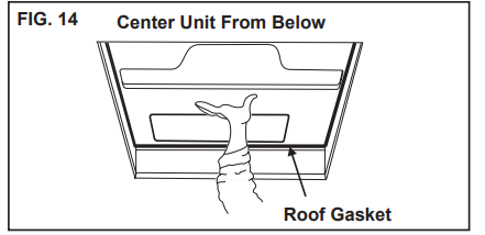
Check gasket alignment of the unit over the roof opening and adjust if necessary. Unit may be moved from below by slightly lifting. See FIG. 14.
- Remove air distribution box and mounting hardware from the air distribution box kit carton.
- Remove wire tie holding center of rear aluminum bracket to plastic template.
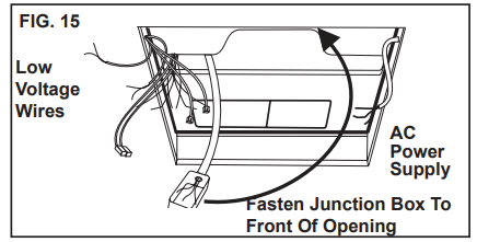
- Reach up into the return air opening and pull the unit electrical wires down for later connection.
Mount the junction box with screws to the framing in front of the 14-1/4" x 14-1/4" (±1/8") opening. See FIG. 15.
- Base Pan Duct Adapter
Remove the liner from the foam tape and position on the base so screw hole and air openings are aligned. See FIG. 16.

- Install screw to help hold duct adapter to base pan if desired.
- 120 VAC Power Supply Connection
WARNING: SHOCK HAZARD. Disconnect 120 VAC at the source. Failure to obey this warning may cause death or severe personal injury.
Note: Wiring MUST comply with National Electrical Code ANSI/NFPA-70 and CSA Standard C22.1 (latest edition) and any State or Local Codes or regulations.- Install the strain relief in the junction box.
- Route the previously run 120 VAC power supply wire through the strain relief into the junction box. Tighten connector making sure not to damage wire.
Note: Connect wiring per schematic with UL listed wire connectors for size of wire being connected.
WARNING: SHOCK HAZARD. This product is equipped with a 2 wire plus ground system for protec-tion against shock hazard. Make sure that the unit is wired into a properly grounded 120 VAC circuit and the polarity is correct. Failure to obey this warning may cause death, severe personal injury or damage to the equipment. - Connect white to white; black to black; and green to green or bare wire using appropriate size wire connector.
- Tape the connectors to the supply wires to assure they don't vibrate off.
- Push the wires into the box.
- Install the junction box cover with screws pro-vided.
- Ceiling template installation
Note: The large center hole in the ceiling template goes to the rear.- Start each mounting bolt by hand before tightening any of them. The threaded inserts in the base pan can be seen to aid in starting the bolts.
- This installation uses a 3 bolt pattern, one in the rear center and two in the front corners. See Fig. 17.
Evenly tighten the bolts to a torque of 40 to 50 inch pounds. This will compress the roof gasket to ap-proximately 1/2". The bolts are self locking so further tightening is not necessary. See FIG. 17.
NOTICE: PROPERTY DAMAGE HAZARD. If bolts are left loose there may not be an adequate roof seal or if over tightened, damage may occur to the unit base or ceiling template. Tighten to torque specifications listed in this manual.
- This installation uses a 3 bolt pattern, one in the rear center and two in the front corners. See Fig. 17.
- Start each mounting bolt by hand before tightening any of them. The threaded inserts in the base pan can be seen to aid in starting the bolts.
- Template/Duct connector
- Pull duct down through template opening.
Cut the duct 1/2"-1" below template opening. See Fig. 17.

- Align the template duct adapter with the tem-plate duct hole making sure the screw holes line up (if not rotate 1/2 turn). Insert template duct adapter into duct. Leave one loop of duct wire below the duct adapter groove. Do not insert tabs inside of the duct.
Snap duct adapter into template and install 2 screws through the duct adapter tabs into the ceiling template. See Fig. 18.

Wiring The System
(Low Voltage Connec-tions)
- CCC, CCC 2 & Digital Thermostat
NOTICE: PROPERTY DAMAGE HAZARD. Disconnect the positive (+) 12 VDC terminal at the sup-ply battery. Failure to obey this warning may cause damage to equipment.
Note: If optional solar panel is to be installed, do so at this time. Follow installation instructions packaged with solar panel.- Connect the previously run 12 VDC supply wire to the red and black wires protruding from the 14-1/4" x 14-1/4" (±1/8") roof open-ing.
- Connect the previously run furnace thermo-stat wires (if applicable) to the blue wires pro-truding from the 14-1/4" x 14-1/4" (±1/8") roof opening. The polarity of these connections does not matter.
- Terminate the previously run 4 conductor communication cable(s) protruding into the 14- 1/4" x 14-1/4" (±1/8") roof opening. The cable(s) must be terminated with a telephone RJ-11-6C4P connector. Refer to the crimp tool manufacturer for crimping instructions. See FIGS. 4 & 5.
Important: RJ-11-6C4P connectors must be installed with the same polarity on each end. Standard telephone cables will not operate the controls. - Plug the communication cable(s) into the telephone coupler(s) in the 14-1/4" x 14-1/4" (±1/8") roof opening. If more than one zone is used on the CCC and CCC 2 models, the second coupler will be used to join each ad-ditional zone.
- Plug the indoor temperature sensor cable (if applicable) into the matching connector pro-truding from the return air opening.
- Energy Management System (CCC an CCC 2 Only). If applicable, connect the previously run Energy Management System wires to the yellow wires protruding from the 14-1/4" x 14-1/4" (±1/8") roof opening. The polarity of this connection does not matter.
- Analog Thermostat
- Connect the previously run 12 VDC supply wire to the red and black wires protruding from the units return air opening. Connect + 12 VDC to the red wire; –12 VDC to the black wire.
- Connect the previously run furnace thermo-stat wires (if applicable) to the blue/white wires protruding from the units return air opening. The polarity of these connections does not matter.
- Connect red/white wire protruding from the units return air opening to the seven wire cable thermostat +7.5 terminal.
- Connect the green wire protruding from the units return air opening to the seven wire ca-ble thermostat “GND” terminal.
- Connect the yellow wire protruding from the units return air opening to the seven wire ca-ble thermostat “COOL” Terminal.
- Connect the tan wire protruding from the units return air opening to the seven wire cable thermostat “FAN” terminal.
- Connect the blue wire protruding from the units return air opening to the seven wire cable thermostat “HI FAN” terminal.
- Connect the orange wire protruding from the units return air opening to the seven wire cable thermostat “HS/HP” terminal (if appli-cable).
- Connect the white wire protruding from the units return air opening to the seven wire ca-ble thermostat “FUR” terminal (if applicable).
- LCD Thermostat
- Connect the previously run +12 VDC supply wire to the red wire protruding from the units return air opening.
- Connect the previously run –12 VDC supply wire to both the black wire protruding from the units return air opening and to the wire of the three wire cable that goes to the thermo-stat 12V– terminal
- Connect the previously run furnace thermo-stat wires (if applicable) to the blue wires pro-truding from the units return air opening.
- Connect the red/white wire protruding from the units return air opening to wire of the three wire cable that goes to thermostat 12V+ terminal.
- Connect the orange wire protruding from the units return air opening to wire of the three wire cable that goes to thermostat COMMS terminal.
Air Distribution Box Installation
Important: The inner walls of the ADB go inside the walls of the ceiling template during installation.
- Working from the rear looking forward with the rear tipped down, place the air distribution box in-ner walls against the inside of the ceiling template walls. Slide the air distribution box backwards un-til it touches the template. Raise the air distribu-tion box to the ceiling. See FIG. 19.
Push up on the ADB at the locations indicated by the paper labels to engage the snap locks. There will be a quiet click heard when each latch en-gages. See FIG. 19.

- Hold the air distribution box to the ceiling with one hand and install two coarse threaded 3.5 mm X 19 mm sharp pointed screws in the location shown in FIG. 20.
- Auxiliary screws may be installed at the locations shown. These are NOT required to secure the ADB to the template, but may be desired for aesthetic purposes in some ceiling geometries. See FIG. 20.
Filter installation. Slide filters into slots in air dis- tribution box. The outward curved side of the filter handle faces the ceiling. See FIG. 20.

This completes the digital, analog, and LCD thermostat unit installation. (Proceed to section K to complete the CCC and CCC 2 thermostat installation)
Verify that all features of the system work. See digital, analog, or LCD thermostat Operating Instructions or User's Guide. Reconnect the 12 VDC and 120 VAC power sup-plies. Check fan speeds, cooling mode, heat pump mode, and furnace mode (if connected). If features do not work, disconnect the 12 VDC and 120 VAC power supplies and verify that all wiring is correct.
System Configuration, Reset & Check Out
(CCC and CCC 2 Thermostat Only)
Now that the system is installed, it is necessary to do a system configuration, reset and check out.
Electronic Control Configuration
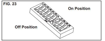
Depending on the equipment options installed by the recreational vehicle manufacturer, the appropriate dip switches will need to be switched to the "ON" position. Placing the switch in the "ON" position selects that option. See FIGS. 21, 22 & 23.
Note: Dip switches are in the "OFF" position when shipped from the factory except on heat strip and (heat pump CCC 2 only) models. On these models the appropriate dip switch, heat strip or (heat pump CCC 2 only), is in the "ON" position from the factory. To gain access to the dip switches, the outside plastic shroud must be removed from the unit. Next remove the electrical box cover. The electrical box will be on the curb side of the RV after installation. See FIGS. 21, 22 & 23.
CCC Dip Switch Selection

- Each CCC thermostat can have up to 4 zones. When only one unit is installed it becomes Zone 1 and no dip switch setting is required. Each additional unit must be assigned a zone (2 through 4). Each unit must have a different zone setting.
- Heat strip selection - On heat strip models the #1 dip switch is in the "ON" position from the factory. Non heat strip models leave in the "OFF" position.
- Furnace selection - when a furnace has been connected to a zone, place the furnace dip switch “ON” for that zone.
- Differential - differential is the temperature difference between the “ON/OFF” cycle of the thermostat in the furnace mode. The nor-mal differential is preset in the circuit board with the dip switch set to the “OFF” position. In some situations, it may be necessary to decrease the differential. The location of the thermostat may create a condition where the normal differential will not maintain your com-fort zone. If this occurs, the differential can be shortened by placing the differential dip switch to the “ON” position.
Note: Setting the differential dip switch should only be re-quired when installation conditions are less than desirable and is not covered under the limited warranty. - Stage selection - stage is not used on these units. Leave in the “OFF” position.
- Gen start selection - leave in the “OFF” posi-tion.
- Replace the unit electrical box cover.
- Repeat this procedure for each additional zone
- CCC 2 Dip Switch Selection
- Ext. Stage - Ext. Stage is not used on this unit. Leave in the “OFF” position.
- Zone selection - Each CCC 2 thermostat can have up to 4 zones. When only one unit is installed it becomes Zone 1 and no dip switch setting is required. Each additional unit must be assigned a zone (2 through 4). Each unit must have a different zone setting.
- Stage selection - Stage is not used on this unit. Leave in the “OFF” position.
- Heat Strip - On heat strip models the #6 dip switch is in the "ON" position from the factory. Non heat strip models leave in the "OFF" position.
- Heat Pump - On heat pump models the #7 dip switch is in the "ON" position from the factory. Non heat pump models leave in the "OFF" position.
- Furnace - If a Furnace/Aqua heat system has been connected to this unit, the furnace dip switch must be placed in the “ON” position.
- Dehumidify - Dehumidify is not used on this unit. Leave in the “OFF” position.
- Gen start selection - Leave in the “OFF” posi-tion.
- Replace the unit electrical box cover and out side plastic shroud.
- Repeat this procedure for each additional zone.
- System Reset
- CCC system
After setting the dip switches in the electronic control, do a system reset.- Turn the ON/OFF switch to the “OFF” position.
- Simultaneously press and hold the MODE and ZONE push-buttons while turning the ON/OFF switch to “ON”. FF should appear in LCD display un-til the mode and zone push-buttons are released
- When a dip switch is turned on after initial configuration, a system reset will need to be done before the CCC thermostat will recognize the updated selection.
- CCC 2 system
After setting the dip switches in the electronic control, do a system reset.- Reconnect the 12 VDC and 120 VAC power supplies.
- Make sure the CCC 2 thermostat is in the “OFF” mode
- Simultaneously press the MODE and ZONE buttons. The LCD will display “IniT” and all available zones.
- Release the MODE and ZONE buttons.
- Press the ON/OFF button to exit system set up.
- When a dip switch is turned on after initial configuration, a system reset will need to be done before the CCC 2 thermostat will recognize the updated selection.
- CCC system
- System Checkout
Verify that all features of the installed system work. See CCC and CCC 2 thermostat Operating Instructions or User’s Guide. Reconnect the 12 VDC and 120 VAC power supplies. Check fan speeds, cooling mode, heat pump mode, and furnace mode (if connected). If the features do not work disconnect the 12 VDC and 120 VAC power supplies and verify that all wiring is correct and that the correct dip switches have been turned on.
Furnace/Aqua Temperature Differential Setting
(CCC 2 Only)
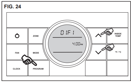
This system can be configured to operate using an ON/OFF differential of either 1 degree F. or 2 degree F. See FIG. 24.
To set the differential, simultaneously press the PROGRAM button and the up button on the CCC 2 thermostat. "diF1" will appear in the display while the buttons are pressed. See FIG. 24. To set the 2 degree differential, simultaneously press the PROGRAM button and the down button. "diF2 will appear in the display while the buttons are pressed.
Setup Guide
Setting up the Dometic Roof Top Unit Air Conditioner 641415.30X involves several steps:
- Preparation: Ensure the roof of your RV is clear of any obstructions and compatible with the air conditioner's dimensions.
- Installation: Follow the manufacturer's guidelines to securely mount the unit onto the roof. This may require professional assistance.
- Electrical Connection: Connect the unit to a 120V AC power source, ensuring all connections are secure and meet safety standards.
- Configuration: Use the digital thermostat or remote control to configure the desired temperature settings.
- Testing: Turn on the air conditioner and check for proper functioning, ensuring all vents are clear and the system is cooling efficiently.
MAINTENANCE
- Air Filters
- Periodically (a minimum of every 2 weeks of op-eration) slide out the return air filters located on the end of the air distribution box. Wash the filters with soap and warm water, let dry and then rein-stall.
Note: To insure easy future removal the filters need to be replaced with the domed side of their handle positioned towards the ceiling.
Note: Never run the unit without both return air filters in place. This will plug the unit evaporator coil with dirt and may substantially degrade the performance of the unit over time.
- Periodically (a minimum of every 2 weeks of op-eration) slide out the return air filters located on the end of the air distribution box. Wash the filters with soap and warm water, let dry and then rein-stall.
- Air Distribution Box Housing
- Clean air distribution box housing with a soft cloth dampened with a mild detergent. Never use furni-ture polish or scouring powders.
- Fan Motor
- The blower motor is factory lubricated and re-quires no service.
- Frost Formation On Cooling Coil
- Frost on a small portion of the coil is not unusual. Under certain conditions, ice may form on the evaporator coil. This is indicated by very cold out-put at very low air speed and the icing can be seen through the hole network with the filters re-moved. If this should occur, inspect the filter and clean if dirty. Make sure air vents are open and not obstructed. Units have a greater tendency to frost when the outside temperature is relatively low. This may be prevented by adjusting the ther-mostat control knob to a warmer setting (counter clockwise). Should frosting continue, operate on any fan ONLY setting until the cooling coil is free of frost; then resume normal operation. If frost condition persist, contact your local service cen-ter for assistance.
SERVICE-UNIT DOES NOT OPERATE
If your unit fails to operate or operates improperly, check the following before calling your service center.
- If RV connected to motor generator, check to be sure motor generator is running and producing power.
- If RV connected to power supply by a land line, check to be sure line is sized properly to run unit load and it is plugged into power supply.
- Check your fuse or circuit breaker to see if it is open. Insure fuse is not burnt, or circuit breaker is "ON" and not activated.
- After the above checks, call your local service center for further help. This unit must be serviced by quali-fied service personnel only.
- When calling for service, always give the following:
- Unit model and serial number found on identification label located on base pan of unit bottom. (Remove filter and view through network of holes)
Air distribution box model and serial number found on rating plate located on ceiling template. Observe this rating plate through the air distribution box right side vent opening.
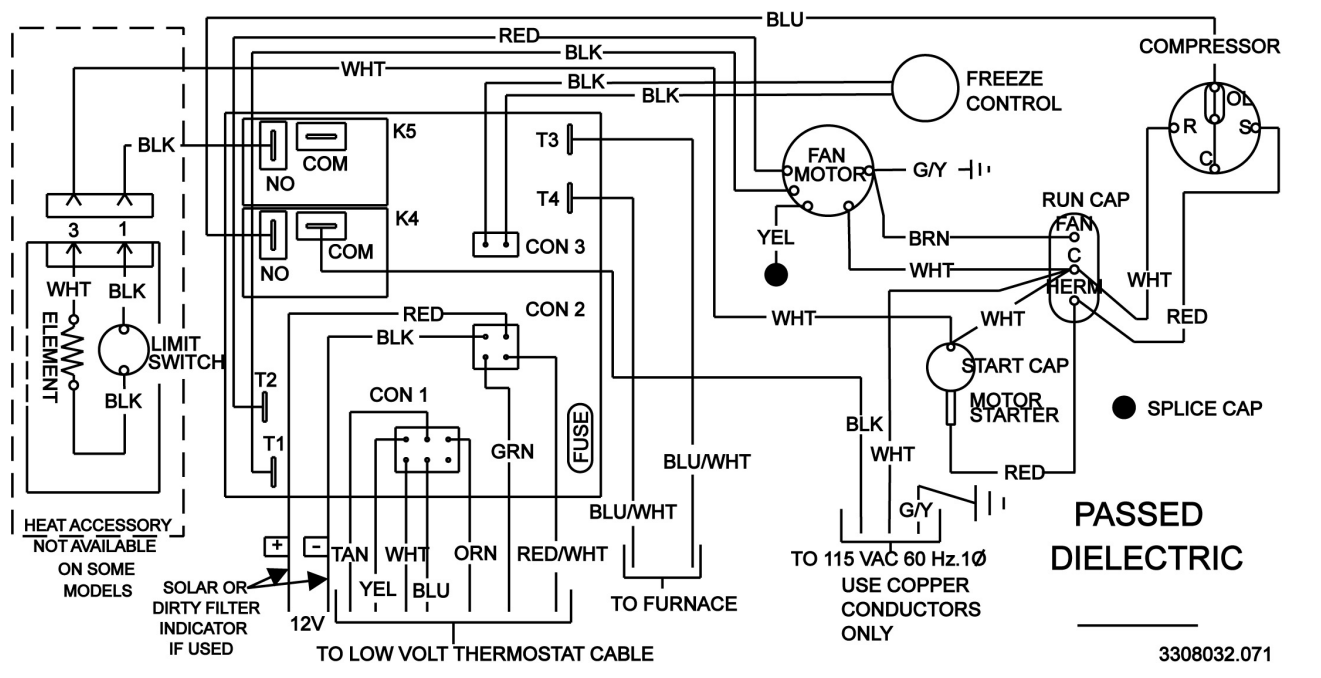
WIRING DIAGRAM
6414 Series
Troubleshooting
If you encounter issues with your Dometic Roof Top Unit Air Conditioner 641415.30X, here are some common problems and solutions:
- No Power: Check the electrical connections and ensure the unit is properly plugged in. Verify that the circuit breaker has not tripped.
- Insufficient Cooling: Ensure the air filter is clean and not clogged. Check for any blockages in the vents or ducts.
- Leaks: Inspect the roof seals and connections for any signs of leaks. Consult a professional if you find any issues.
- Warning: Always turn off the power before performing any maintenance or repairs to avoid electrical shock or injury.
Pros & Cons
Pros
- High Performance: Delivers efficient cooling even in extreme temperatures.
- Durable Construction: Built to withstand harsh weather conditions.
- Ease of Use: Digital thermostat and remote control make temperature adjustment simple.
- Compact Design: Fits seamlessly onto most RV roofs without obstructing other accessories.
- Low Noise Operation: Minimizes disturbance during operation.
Cons
- Installation Complexity: May require professional assistance for installation.
- High Energy Consumption: Requires a significant power source which can increase energy costs.
- Weight: The unit is relatively heavy, requiring careful handling during installation.
- Maintenance: Regular cleaning of the air filter and checks for leaks are necessary to maintain performance.
Customer Reviews
Customers have generally praised the Dometic Roof Top Unit Air Conditioner 641415.30X for its robust performance and ease of use. Many have noted that it provides excellent cooling even in very hot conditions and is relatively quiet during operation. However, some users have mentioned that the installation process can be challenging and requires professional help. Common complaints include high energy consumption and the need for regular maintenance to keep the unit running efficiently.
Faqs
What is the cooling capacity of the Dometic?
How much power does the Dometic Conditioner 641415.30X consume?
Is the Roof Top Unit Air Conditioner easy to install?
What are the dimensions of the 641415.30X?
How heavy is the Dometic?
Does theAir Conditioner come with a remote control?
What kind of maintenance is required for the Dometic?
Can I use the Dometic Roof Top Unit Air Conditioner in extreme weather conditions?
Is the Roof Top Unit Air Conditioner energy-efficient?
Leave a Comment