Elegoo Starter Kit MEGA2560 Owners Manual

Content
Introduction
The package includes the MEGA2560 microcontroller, which is perfect for sophisticated projects because it has more memory and input/output ports than conventional Arduino boards. With the extensive selection of components included in the Elegoo Starter Kit, users may construct a vast array of projects. These components include LEDs, resistors, sensors, motors, and more. The kit offers a practical way to learn electronics and programming through in-depth tutorials and sample projects. The Elegoo Starter Kit MEGA2560 provides a strong foundation for exploring the world of electronics and realizing your creative ideas, whether you're a student, enthusiast, or educator.
Detailed Specifications
The Elegoo Starter Kit MEGA2560 features the MEGA2560 board, which boasts a powerful 8-bit Atmel AVR microcontroller with 256KB of flash memory and 8KB of SRAM.
The board also includes
- 54 digital input/output pins,
- 16 analog inputs,
- 4 UARTs (hardware serial ports),
- a 16 MHz crystal oscillator,
- a USB connection,
- a power jack,
- an ICSP header, and
- a reset button.
The kit also includes a variety of modules, such as
- a LCD1602 module,
- a servo motor,
- a DC motor,
- a relay module,
- a temperature sensor,
- a light sensor, and more.
Installing IDE
Introduction
The Arduino Integrated Development Environment (IDE) is the software side of the Arduino platform. In this lesson, you will learn how to setup your computer to use Arduino and how to set about the lessons that follow. The Arduino software that you will use to program your Arduino is available for Windows, Mac and Linux. The installation process is different for all three platforms and unfortunately there is a certain amount of manual work to install the software.
STEP 1: Go to https://www.arduino.cc/en/Main/Software and find below page.
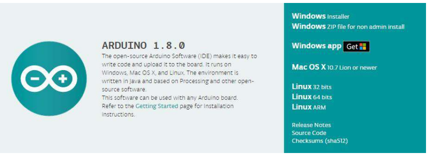
The version available at this website is usually the latest version, and the actual version may be newer than the version in the picture.
STEP2:Download the development software that is compatible with the operating system of your computer. Take Windows as an example here.
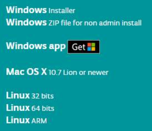
Click Windows Installer.

Click JUST DOWNLOAD.
Also version 1.8.0 is available in the material we provided, and the versions of our materials are the latest versions when this course was made.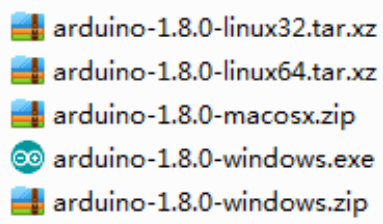
Installing Arduino (Windows)
Install Arduino with the exe. Installation package.
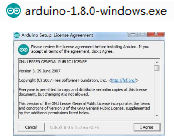
Click I Agree to see the following interface
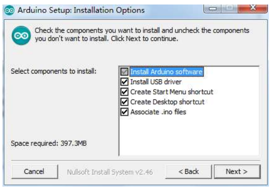
Click Next
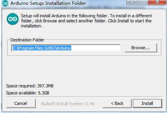
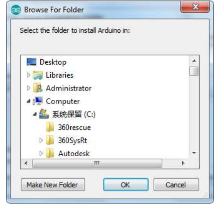
You can press Browse… to choose an installation path or directly type in the directory you want.
Click Install to initiate installation
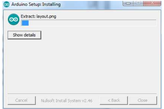
Finally, the following interface appears, click Install to finish the installation.
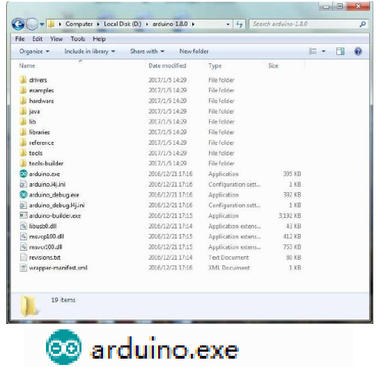
- Next, the following icon appears on the desktop
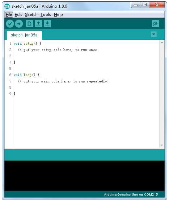
Double-click to enter the desired development environment
You may directly choose the installation package for installation and skip the contents below and jump to the next section. But if you want to learn some methods other than the installation package, please continue to read the section.
Unzip the zip file downloaded, Double-click to open the program and enter the desired development environment
However, this installation method needs separate installation of driver.
- The Arduino folder contains both the Arduino program itself and the drivers that allow the Arduino to be connected to your computer by a USB cable.
- Before we launch the Arduino software, you are going to install the USB drivers.
- Plug one end of your USB cable into the Arduino and the other into a USB socket on your computer. The power light on the LED will light up and you may get a 'Found New Hardware' message from Windows. Ignore this message and cancel any attempts that Windows makes to try and install drivers automatically for you.
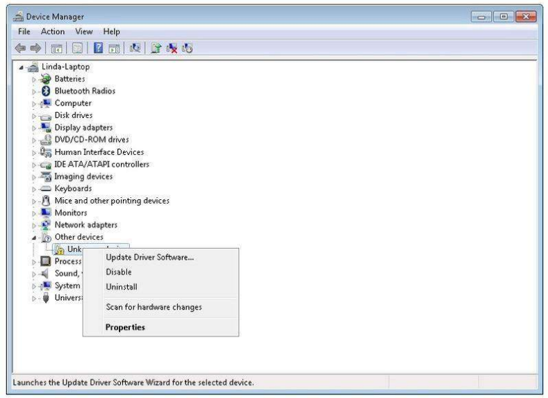
- The most reliable method of installing the USB drivers is to use the Device Manager.
- This is accessed in different ways depending on your version of Windows. In Windows 7, you first have to open the Control Panel, then select the option to view Icons, and you should find the Device Manager in the list.
- Under ‘Other Devices’, you should see an icon for ‘unknown device’ with a little yellow warning triangle next to it. This is your Arduino.
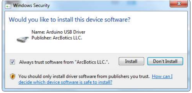
Right-click on the device and select the top menu option (Update Driver Software...). You will then be prompted to either ‘Search Automatically for updated driver software’ or ‘Browse my computer for driver software’. Select the option to browse and navigate to the X\arduino1.8.0\drivers.

Click 'Next' and you may get a security warning, if so, allow the software to be installed. Once the software has been installed, you will get a confirmation message.

- Windows users may skip the installation directions for Mac and Linux systems and jump to Lesson 1. Mac and Linux users may continue to read this section.
Installing Arduino (Mac OS X)
Download and Unzip the zip file, double click the Arduino.app to enter Arduino IDE; the system will ask you to install Java runtime library if you don’t have it in your computer. Once the installation is complete you can run the Arduino IDE.

Installing Arduino (Linux)
You will have to use the make install command. If you are using the Ubuntu system, it is recommended to install Arduino IDE from the software center of Ubuntu.
TIPS: If you have problems in installing the drivers, please refer to the UNO R3, MEGA, NANO DRIVER FAQ.

Description
For those who are interested in learning more about Arduino and physical computing, the Elegoo Starter Kit MEGA2560 is an ideal place to start. The kit comes with a comprehensive handbook that offers step-by-step directions for a variety of experiments and projects, from simple to complex. In addition, the handbook offers troubleshooting advice, source code, and circuit schematics. This kit teaches you how to operate LEDs, motors, and sensors; it also shows you how to show data on an LCD screen and send serial data to other devices, among many other things.
Digital Inputs
Overview
In this lesson, you will learn to use push buttons with digital inputs to turn an LED on and off. Pressing the button will turn the LED on; pressing the other button will turn the LED off.
Component Required
- (1) x Elegoo Mega2560 R3
- (1) x 830 Tie-points Breadboard
- (1) x 5mm red LED
- (1) x 220 ohm resistor
- (2) x push switches
- (7) x M-M wires (Male to Male jumper wires)
Component Introduction
PUSH SWITCHES
Switches are really simple components. When you press a button or flip a lever, they connect two contacts together so that electricity can flow through them. The little tactile switches that are used in this lesson have four connections, which can be a little confusing.
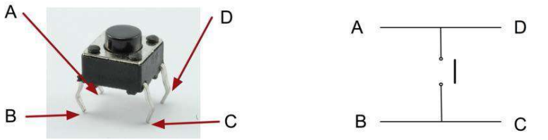
- Actually, there are only really two electrical connections. Inside the switch package, pins B and C are connected together, as are A and D.
Connection
Schematic
Wiring diagram
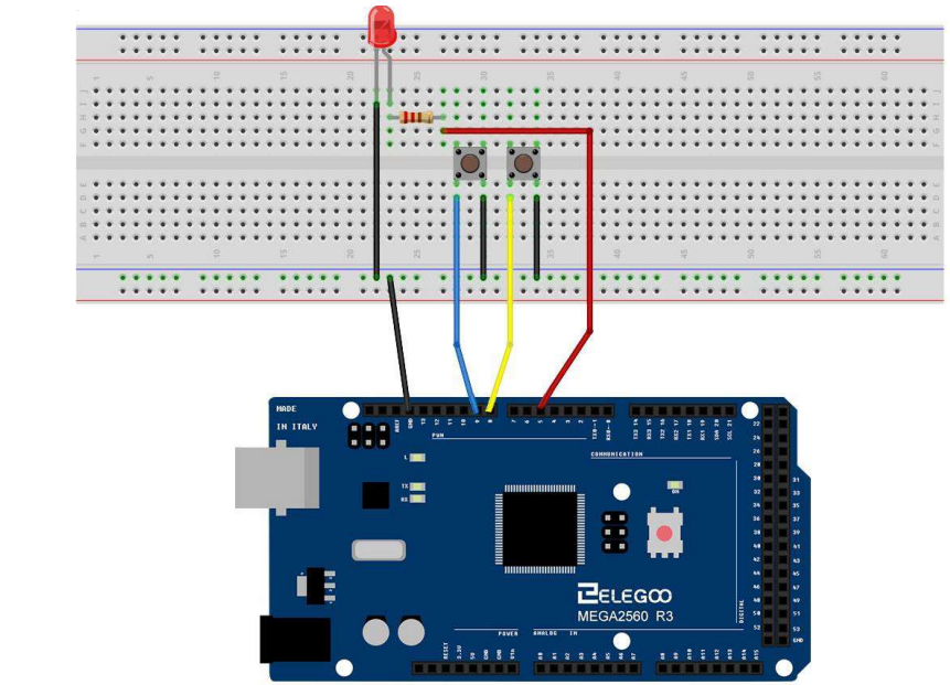
Although the bodies of the switches are square, the pins protrude from opposite sides of the switch. This means that the pins will only be far enough apart when they are placed correctly on the breadboard. Remember that the LED has to have the shorter negative lead to the left.
Code
- After wiring,please open program in the code folder- Lesson 5 Digital Inputs, and press UPLOAD to upload the program. If errors are prompted, see Lesson 2 for details about the tutorial on program upload.
- Load the sketch onto your MEGA2560 board. Pressing the left button will turn the LED on while pressing the right button will turn it off.
- The first part of the sketch defines three variables for the three pins that are to be used. The 'ledPin' is the output pin and 'buttonApin' will refer to the switch nearer the top of the breadboard and 'buttonBpin' to the other switch.
- The 'setup' function defines the ledPin as being an OUTPUT as normal, but now we have the two inputs to deal with. In this case, we use the set the pinMode to be 'INPUT_PULLUP' like this:
- pinMode(buttonApin, INPUT_PULLUP);
- pinMode(buttonBpin, INPUT_PULLUP);
- The pin mode of INPUT_PULLUP means that the pin is to be used as an input, but that if nothing else is connected to the input, it should be 'pulled up' to HIGH. In other words, the default value for the input is HIGH, unless it is pulled LOW by the action of pressing the button. \
- This is why the switches are connected to GND. When a switch is pressed, it connects the input pin to GND, so that it is no longer HIGH.
- Since the input is normally HIGH and only goes LOW when the button is pressed, the logic is a little upside down. We will handle this in the 'loop' function. void loop()
- if (digitalRead(buttonApin) == LOW) { digitalWrite(ledPin, HIGH); }
- if (digitalRead(buttonBpin) == LOW) { digitalWrite(ledPin, LOW); }
- In the 'loop' function there are two 'if' statements. One for each button. Each does an 'digitalRead' on the appropriate input.
- Remember that if the button is pressed, the corresponding input will be LOW, if button A is low, then a 'digitalWrite' on the ledPin turns it on.
- Similarly, if button B is pressed, a LOW is written to the ledPin.
Example picture
Photocell
Overview
In this lesson, you will learn how to measure light intensity using an Analog Input. You will build on lesson 25 and use the level of light to control the number of LEDs to be lit. The photcell is at the bottom of the breadboard, where the pot was above.
Component Required
- (1) x Elegoo Mega2560 R3
- (1) x 830 tie-points breadboard (8) x leds
- (8) x 220 ohm resistors
- (1) x 1k ohm resistor
- (1) x 74hc595 IC
- (1) x Photoresistor (Photocell)
- (16) x M-M wires (Male to Male jumper wires)
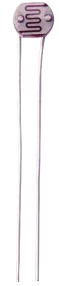
Component Introduction
PHOTOCELL: The photocell used is of a type called a light dependent resistor, sometimes called an LDR. As the name suggests, these components act just like a resistor, except that the resistance changes in response to how much light is falling on them. This one has a resistance of about 50 kΩ in near darkness and 500 Ω in bright light. To convert this varying value of resistance into something we can measure on an MEGA2560 R3 board's analog input, it needs to be converted into a voltage. The simplest way to do that is to combine it with a fixed resistor.

The resistor and photocell together behave like a pot. When the light is very bright, then the resistance of the photocell is very low compared with the fixed value resistor, and so it is as if the pot were turned to maximum. When the photocell is in dull light, the resistance becomes greater than the fixed 1 kΩ resistor and it is as if the pot were being turned towards GND. Load up the sketch given in the next section and try covering the photocell with your finger, and then holding it near a light source.
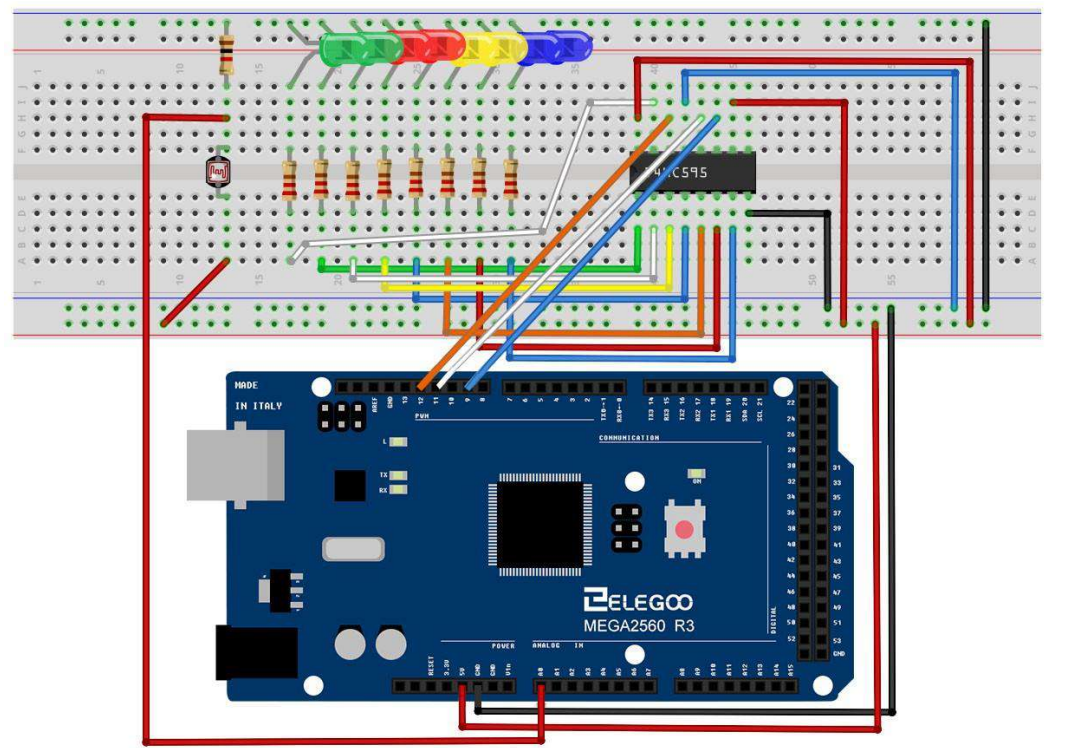
Connection
Schematic
Wiring diagram
Code
- After wiring, please open the program in the code folder- Lesson 26 Photocell and click UPLOAD to upload the program. See Lesson 2 for details about program uploading if there are any errors.
- The first thing to note is that we have changed the name of the analog pin to be 'lightPin' rather than 'potPin' since we no longer have a pot connected.
- The only other substantial change to the sketch is the line that calculates how many of the LEDs to light: int numLEDSLit = reading / 57; // all LEDs lit at 1k
- This time, we divide the raw reading by 57 rather than 114. In other words, we divide it by half as much as we did with the pot to split it into nine zones, from no LEDs lit to all eight lit. This extra factor is to account for the fixed 1 kΩ resistor. This means that when the photocell has a resistance of 1 kΩ (the same as the fixed resistor), the raw reading will be 1023 / 2 = 511. This will equate to all the LEDs being lit and then a bit (numLEDSLit) will be 8.
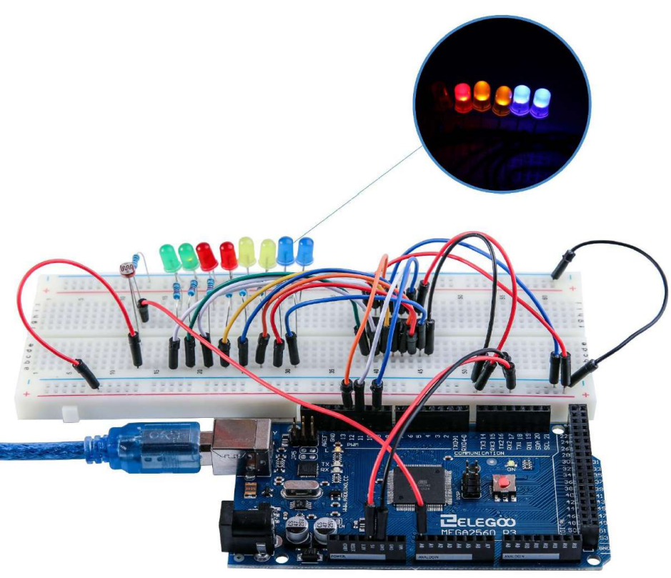
Example picture
Stepper Motor
Overview
In this lesson, you will learn a fun and easy way to drive a stepper motor. The stepper we are using comes with its own driver board making it easy to connect to our MEGA2560.
Component Required
- (1) x Elegoo Mega2560 R3
- (1) x 830 tie-points breadboard
- (1) x ULN2003 stepper motor driver module
- (1) x Stepper motor
- (1) x 9V1A Adapter
- (1) x Power supply module
- (6) x F-M wires (Female to Male DuPont wires)
- (1) x M-M wire (Male to Male jumper wire)
Component Introduction
Stepper Motor
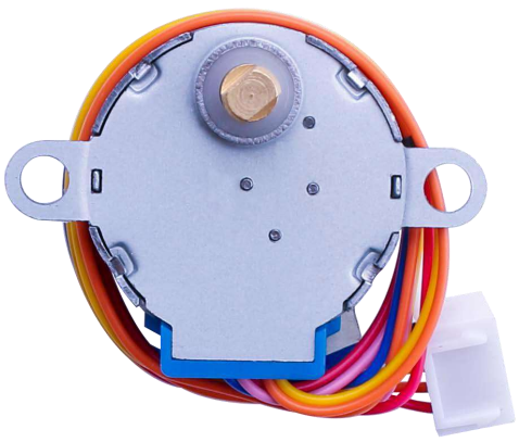
A stepper motor is an electromechanical device which converts electrical pulses into discrete mechanical movements. The shaft or spindle of a stepper motor rotates in discrete step increments when electrical command pulses are applied to it in the proper sequence. The motors rotation has several direct relationships to these applied input pulses. The sequence of the applied pulses is directly related to the direction of motor shafts rotation. The speed of the motor shafts rotation is directly related to the frequency of the input pulses and the length of rotation is directly related to the number of input pulses applied.One of the most significant advantages of a stepper motor is its ability to be accurately controlled in an open loop system. Open loop control means no feedback information about position is needed. This type of control eliminates the need for expensive sensing and feedback devices such as optical encoders. Your position is known simply by keeping track of the input step pulses.
Stepper motor 28BYJ-48 Parameters
- Model: 28BYJ-48
- Rated voltage: 5VDC
- Number of Phases: 4
- Speed Variation Ratio: 1/64
- Stride Angle: 5.625° /64
- Frequency: 100Hz
- DC resistance: 50Ω±7%(25℃)
- Idle In-traction Frequency: > 600Hz
- Idle Out-traction Frequency: > 1000Hz
- In-traction Torque >34.3mN.m(120Hz)
- Self-positioning Torque >34.3mN.m
- Friction torque: 600-1200 gf.cm
- Pull in torque: 300 gf.cm
- Insulated resistance >10MΩ(500V)
- Insulated electricity power:600VAC/1mA/1s
- Insulation grade:A
- Rise in Temperature <40K(120Hz)
- Noise <35dB(120Hz,No load,10cm)
Interfacing circuits
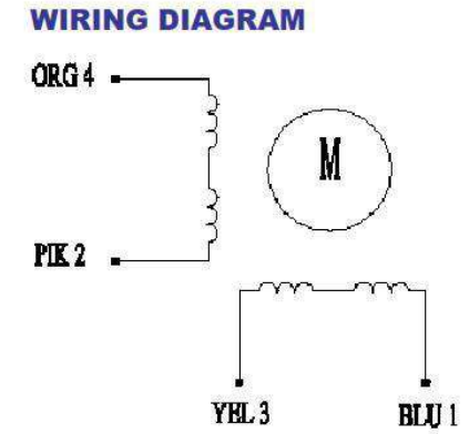
The bipolar stepper motor usually has four wires coming out of it. Unlike unipolar steppers, bipolar steppers have no common center connection. They have two independent sets of coils instead. You can distinguish them from unipolar steppers by measuring the resistance between the wires. You should find two pairs of wires with equal resistance. If you’ve got the leads of your meter connected to two wires that are not connected (i.e. not attached to the same coil), you should see infinite resistance (or no continuity).
ULN2003 Driver Board
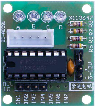
Product Description
- Size: 42mmx30mm
- Use ULN2003 driver chip, 500mA
- A. B. C. D LED indicating the four phase stepper motor working condition.
- White jack is the four phase stepper motor standard jack.
- Power pins are separated
- We kept the rest pins of the ULN2003 chip for your further prototyping.
The simplest way of interfacing a unipolar stepper to Arduino is to use a breakout for ULN2003A transistor array chip. The ULN2003A contains seven darlington transistor drivers and is somewhat like having seven TIP120 transistors all in one package. The ULN2003A can pass up to 500 mA per channel and has an internal voltage drop of about 1V when on. It also contains internal clamp diodes to dissipate voltage spikes when driving inductive loads.To control the stepper, apply voltage to each of the coils in a specific sequence.
The sequence would go like this:
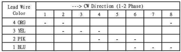
Here are schematics showing how to interface a unipolar stepper motor to four controller pins using a ULN2003A, and showing how to interface using four com
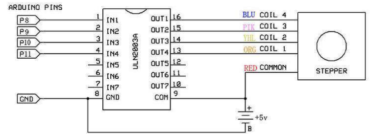
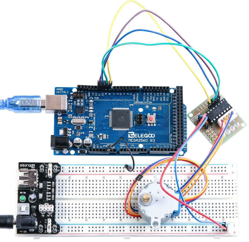
Connection
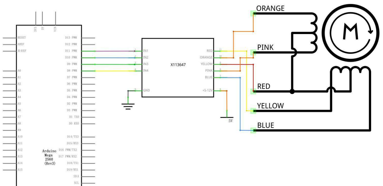
Schematic

Wiring diagram
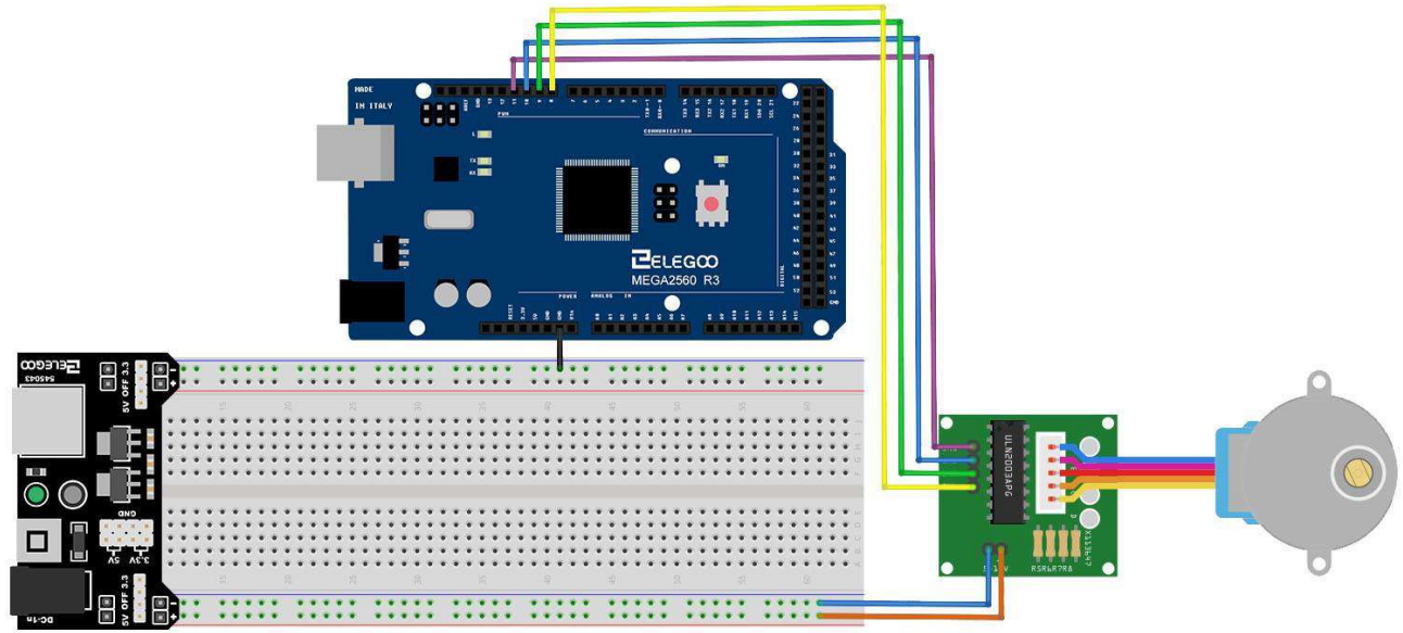
- We are using 4 pins to control the Stepper.
- Pin 8-11 are controlling the Stepper motor.
- We connect the Ground from to MEGA2560 to the Stepper motor.
Code
- After wiring, please open the program in the code folder- Lesson 31 Stepper Motor and click UPLOAD to upload the program. See Lesson 2 for details about program uploading if there are any errors.
- Before you can run this, make sure that you have installed the < Stepper > library or re-install it, if necessary. Otherwise, your code won't work.
For details about loading the library file, see Lesson 1.
Example picture
Setup Guide
To begin using the Elegoo Starter Kit MEGA2560, take the following actions:
- On your PC, install the Arduino IDE.
- Use a USB cable to link the MEGA2560 board to your computer.
- From the Arduino IDE's Tools > Board menu, choose the MEGA2560 board.
- From the Tools > Port menu, choose the appropriate serial port.
- To upload an example drawing to the board, open it.
- To compile and upload the sketch to the board, click the Upload button.
- As instructed in the handbook, attach the modules and sensors to the board.
- To operate the modules and sensors, make necessary changes to the sketch.
Troubleshooting
If you encounter any issues with the Elegoo Starter Kit MEGA2560, try the following troubleshooting steps:
- Check the connections between the board and the modules/sensors.
- Make sure you have selected the correct board and serial port in the Arduino IDE.
- Try using a different USB cable or computer to rule out any issues with the cable or computer.
- Check the manual and source code for any errors or inconsistencies.
- Consult the Elegoo community forum for additional support and troubleshooting tips.
Elegoo Starter Kit MEGA2560 Pros & Cons
Pros
- Affordable price
- Wide range of modules and sensors
- Detailed manual with step-by-step instructions
- Compatible with Arduino IDE
- Powerful microcontroller with plenty of memory and I/O pins
Cons
- Some modules and sensors may be of lower quality compared to more expensive kits
- The manual may be overwhelming for beginners with no prior experience in electronics or programming
Customer Reviews
Customers who have purchased the Elegoo Starter Kit MEGA2560 have generally praised the kit for its affordability, variety of modules and sensors, and detailed manual. However, some customers have noted that some modules and sensors may be of lower quality compared to more expensive kits. Overall, the kit has received positive reviews from beginners and experienced makers alike.
Faqs
What is the difference between the MEGA2560 and the UNO boards?
Can I use the Arduino IDE to program the board?
What modules and sensors are included in the kit?
Do I need any prior experience in electronics or programming to use this kit?
Can I use this kit for commercial projects or applications?
What is the return policy for this kit?
What is the warranty for this kit?
Can I use this kit with other Arduino-compatible boards or shields?
What software do I need to program the MEGA2560 board?
How do I update the firmware on the MEGA2560 board?
Leave a Comment