Ge 4-Wire Switches & Dimmers User Guide | Installation
Content
Introduction of GE 4-Wire Switches & Dimmers
Upgrade your home's lighting control with GE's innovative switches and dimmers. These devices deliver smooth, energy-efficient operation while enhancing the style of your living space. The estimated price ranges from $20 to $40, with no official launching date announced yet.
Detailed Specifications
- 4-wire grounded connection for safety and compatibility with most lighting systems
- Compatible with LED, CFL, and incandescent bulbs, with load capacities up to 600W
- Slim, modern design available in various colors and finishes
- Easy-to-use push-button or slide-control options
- Wireless connectivity for remote control and smart home integration
- Dimming range from 100% to 1% for ultimate lighting control
Description of GE 4-Wire
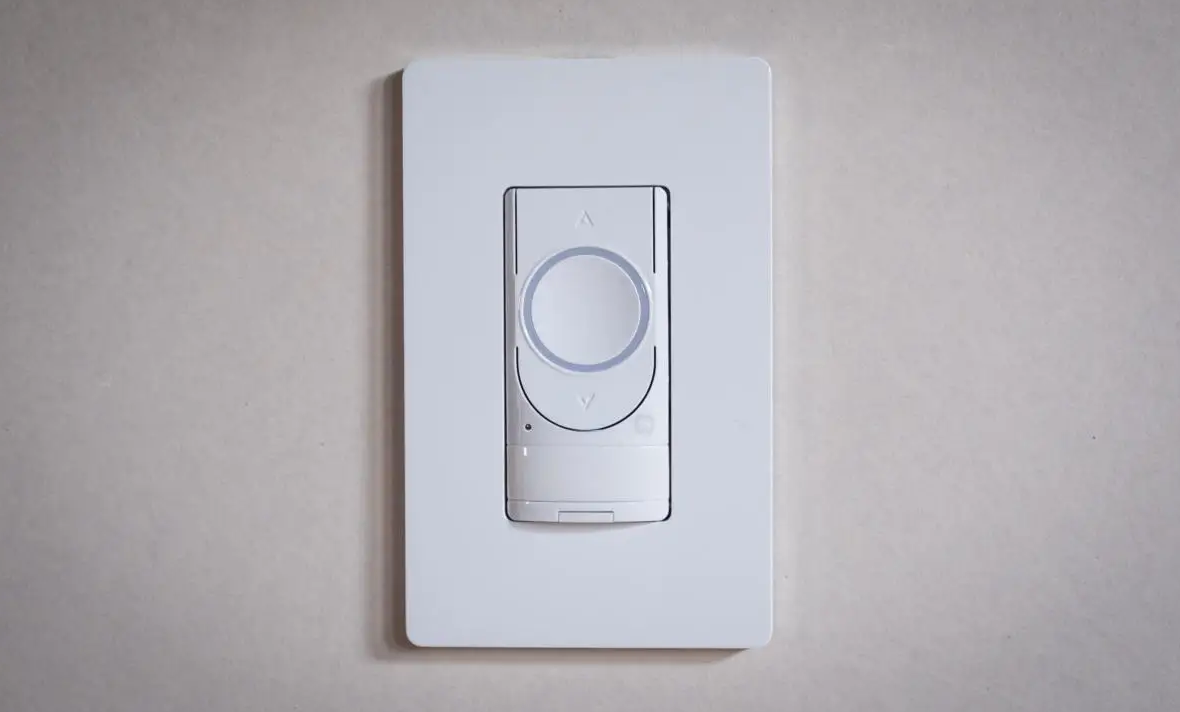
GE 4-wire switches and dimmers provide a modern, user-friendly solution for managing your home's lighting. With a sleek design and multiple color options, these devices blend seamlessly with any décor. These switches are compatible with most bulb types, ensuring versatility and energy efficiency. By integrating wireless connectivity, you can manage your lighting through smartphone apps or voice assistants, creating a truly connected home.
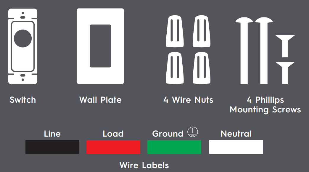
INCLUDED
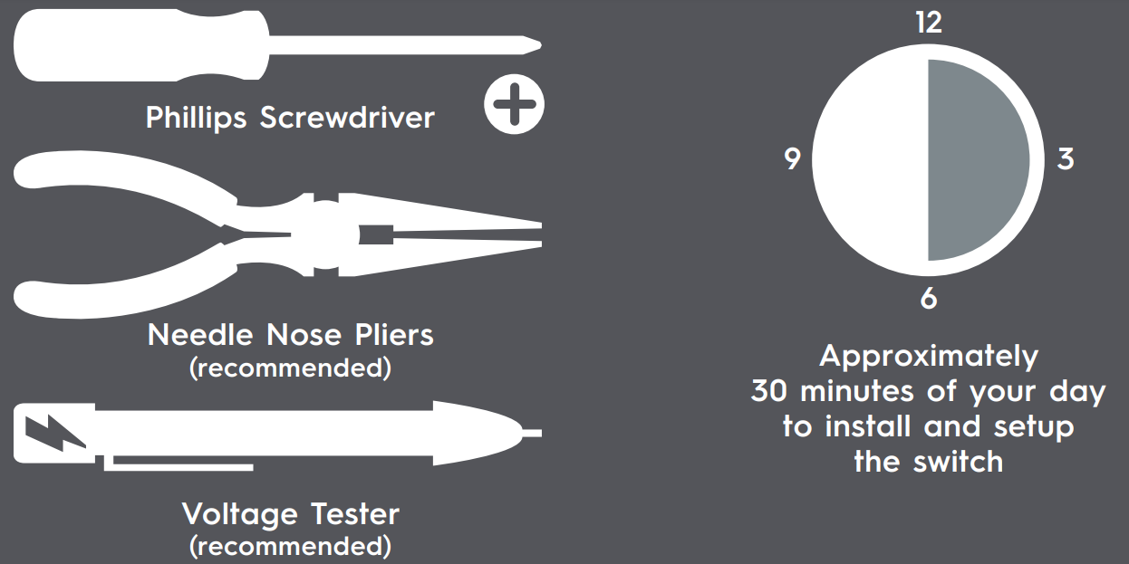
Required tools
Setup Guide
- Turn off the power to the circuit at your home's breaker box
- Remove the existing switch or dimmer, noting wire configurations
- Connect the 4-wire switch or dimmer according to the included instructions
- Restore power to the circuit and test the switch for proper functionality
- Download the recommended app for smartphone or voice assistant integration
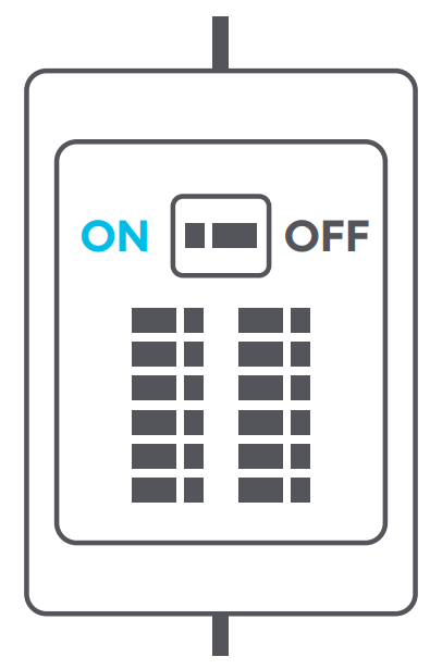
Turn Off The Power
- Turn off the power for the switch location at the circuit breaker box.
- Remove wall plates and mounting screws for both switches you are replacing.
- Gently pull switches out from their boxes so the wiring can be viewed.
- Test the wires with a voltage tester to ensure power is off. If multiple switches are in the same box, test them as well. Additional breakers may need to be turned off.
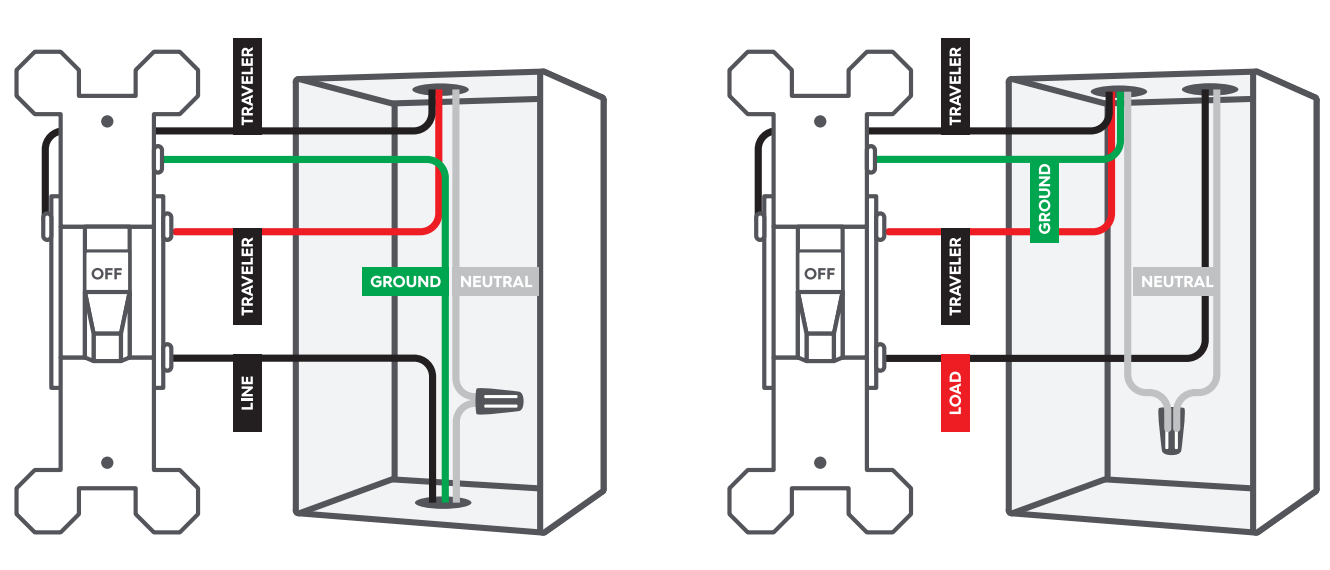
Compatible Wiring
- Do not disconnect any wires at this stage. We recommend taking a picture of your wiring before proceeding for future reference.
- Wiring colors may vary. In this diagram, neutral is white, and ground is bare copper. The red and black wires connected to brass terminals are traveler wires. The wires connected to the black (common) terminals are the line and load (we’ll identify which one is which in STEP 4).
- Both the neutral and ground wires are required for the C by GE Smart Switch.
- If neutral wires are only in one switch location, the traveler wire will be used to carry the neutral to the other switch (this will be explained on STEP 7.B).
- If all necessary wiring is present, you can proceed with installation.
- 6. If installing a 4-way, check for compatible wiring on the 4-way switch.
Restore Power
Restore power to the switches at the circuit breaker box.
LINE And LOAD
- Make sure that the light is off. Then, check the black common terminals on both switches using a voltage tester. One of them should test positive for voltage, and the other one should not.
- Wire that has voltage = LINE
- Wire that doesn’t have voltage = LOAD
- The wire box that houses your line wire will be your line side box/switch while the box that houses your load wire will be your load side box/switch.
- If you are installing a 4-way/multi-way setup, the 4-way switch will have 2 black screws and 2 copper colored screws.
Turn Off The Powe
Turn off the power for the switch location at the circuit breaker box.
Identify And Label Wires
Before disconnecting the wires from the switch, label each wire with the provided labels.
- Line: Based on STEP 4, label the LINE wire that did test positive for voltage.
- Load: Based on STEP 4, label the LOAD wire that did not test positive for voltage.
- Neutral: Standard switches do not require them, but the neutral wires will be present in the box. Look for two or more wires (usually white) not connected to the switch and grouped together with a wire nut. In the event that only one switch box has a neutral, use STEP 7.B for additional wiring instructions.
- Ground: These are usually a group of bare copper or green wires that are sometimes connected to the green ground terminal of the original switch. If not connected to the original switch, they should be in the back of the box.
- Travelers: The traveler wires are connected to the brass screws on the original switches. These wires are in the same sheathed cable and should be different colors that can vary between black, white, or red. One of these wires will be used to provide power to the C by GE Smart Switch on the load side of the circuit. If only one box has a neutral wire, the second traveler will be used as well. Follow instructions shown on STEP 7.B for this situation.
NOTE: If you're installing a 4-way switch, the travelers will be connected to the copper-colored and black screws.
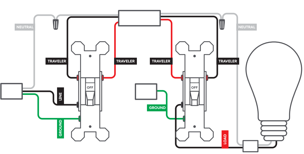
3-Way Install
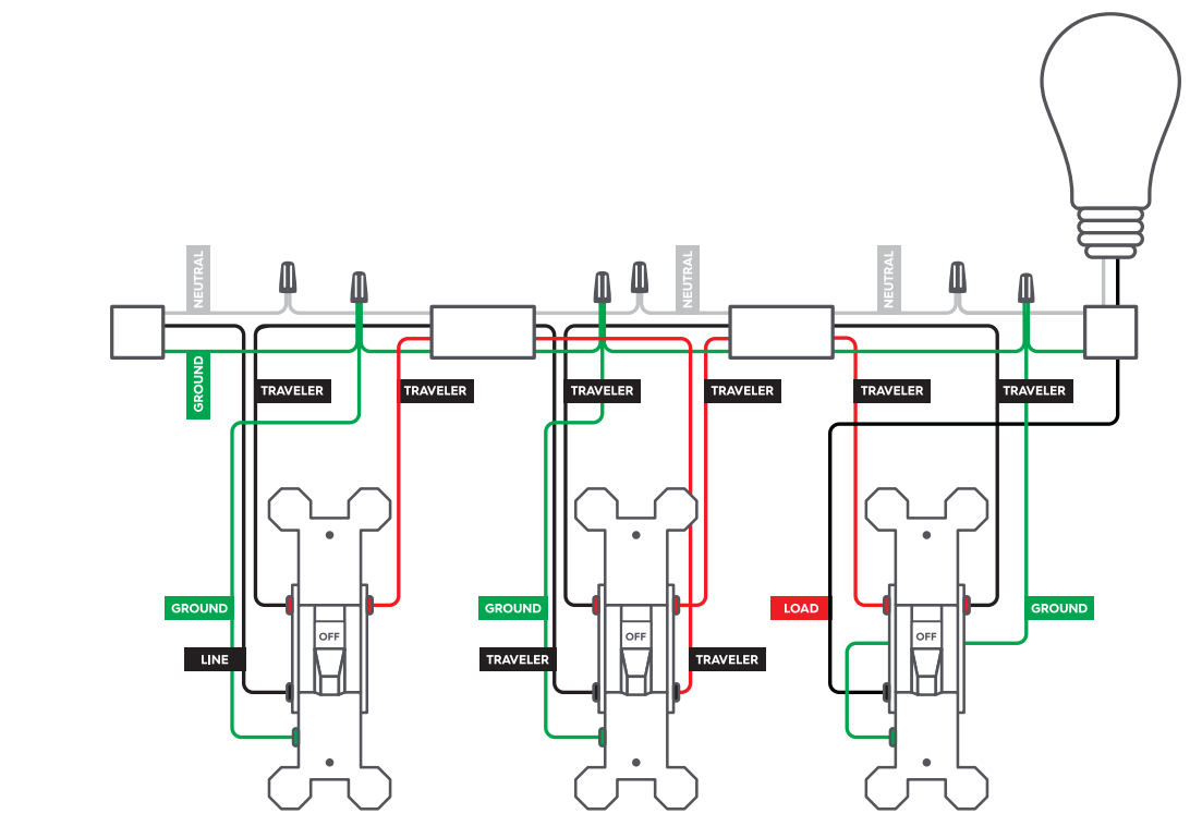
4-Way/Multi-Way Install
Install The Switches
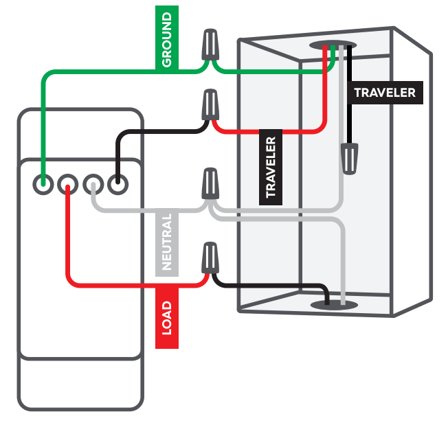
Now that you have successfully identified and labeled each wire, you can disconnect the wires and remove the original switches. Installing Switches Where Neutral Wires Exist in Both Boxes Line Side
- Connect the LINE wire and one of the TRAVELER wires from the wall to the black LINE wire on the C by GE Smart Switch.
- Connect all NEUTRAL wires from the wall to the white NEUTRAL wire on the C by GE Smart Switch.
- Cap the red LOAD wire on the C by GE Smart Switch.
- Connect the GROUND wire from the wall to the green GROUND wire on the C by GE Smart Switch.
- Cap the second TRAVELER wire from the wall. This wire is not needed.
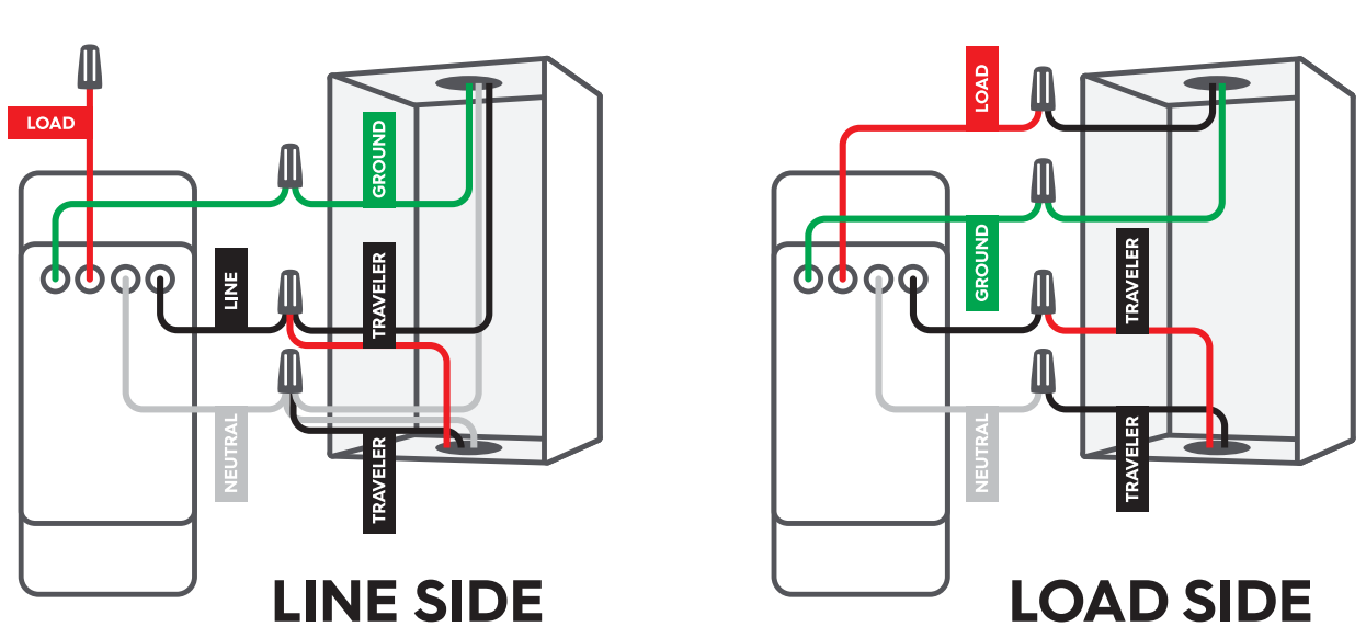
Load Side
- Connect the TRAVELER connected to the black LINE wire in the first box to the black LINE wire on the C by GE Smart Switch.
- Connect all NEUTRAL wires from the wall to the white NEUTRAL wire on the C by GE Smart Switch.
- Connect the LOAD wire from the wall to the red LOAD wire on the C by GE Smart Switch.
- Connect the GROUND wire from the wall to the green GROUND wire on the C by GE Smart Switch.
- Cap the second TRAVELER wire from the wall. This wire is not needed.
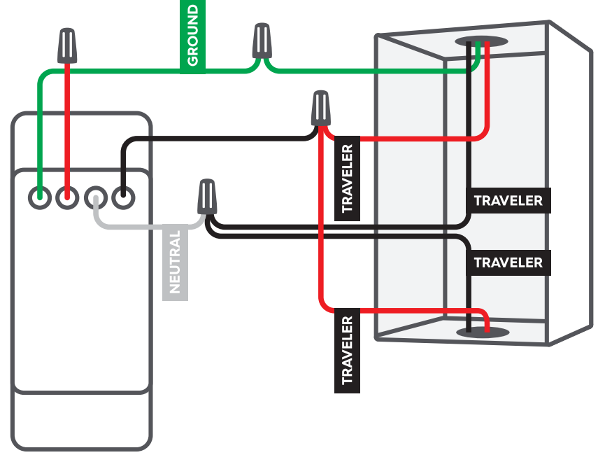
If installing a 4-way/Multi-Way setup
- Connect the GROUND wire from the wall to the green GROUND wire on the C by GE Smart Switch.
- Cap the red LOAD wire on the C by GE Smart Switch.
- Connect the NEUTRAL wires that are associated with that circuit/switch group from the wall to the white NEUTRAL wire on the C by GE Smart Switch.
IMPORTANT: If unsure which NEUTRAL wire is in which circuit/switch group, contact C by GE customer support or a certified electrician. - Connect the two black TRAVELER wires to the black LINE wire on the C by GE Smart Switch.
- Cap the two red TRAVELER wires from the wall. These wires are not needed.
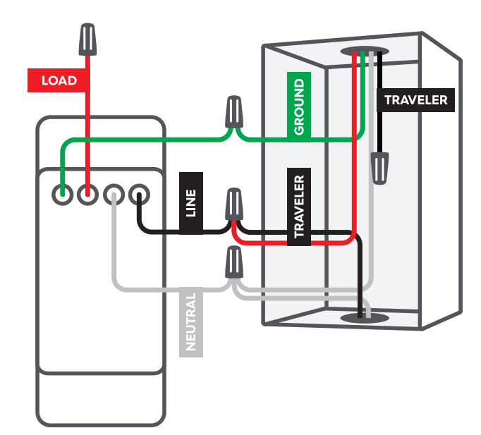
Connect Additional Traveler Wire (Neutral Wires Exist in Only One Box)
- Line Side
The NEUTRAL wires should be in this location. Add the second TRAVELER wire from the wall to all NEUTRAL wires. - Load Side
Connect the second TRAVELER wire to the white NEUTRAL wire on the C by GE Smart Switch.
If installing a 4-way/Multi-Way setup
- Connect the GROUND wire from the wall to the green GROUND wire on the C by GE Smart Switch.
- Cap the red LOAD wire on the C by GE Smart Switch.
- Connect the two black TRAVELER wires to the white NEUTRAL wire on the C by GE Smart Switch.
- Connect the two red TRAVELER wires in the wall to the black LINE wire on the C by GE Smart Switch.
Functionality
IMPORTANT: Only the load switch will turn the light on/off until the two smart switches are linked in the C by GE app. The dimmer buttons will not work on either switch until the two smart switches are linked in the C by GE app. We will handle the app setup in STEP 12.
- Restore power to the switches at the circuit breaker box.
- The light ring on both switches will flash blue indicating the switches are wired correctly. If you see this, proceed to STEP 9.
- The light ring may not illuminate if wired incorrectly.
- The light ring will flash red if the circuit is overloaded. Max load rating is 150W for LED and 450W for incandescent/halogen.
- If lights don't turn on:
- Check that the air gap on the bottom of switch is fully inserted (dimmer/motion switches only).
- Check that power to the switch is back on at the breaker.
- Turn power off at the breaker, return to the switch to confirm the wires are securely and properly wired according to the installation guide.
Turn off the power for the switch location at the circuit breaker box.
Secure The Switch
- Neatly push the wires back into the boxes.
- Using the screws provided, secure the switch to the wall until level and flush.
- Using the screws provided, secure the face plate bracket.
- Snap the face plate cover onto the bracket.
Restore Power
Restore power to the switches at the circuit breaker box.
Enable 3-Way/Multi-Way Control in The C by GE App
NOTE: Only the Load switch will turn the light on/off until the smart switches are linked in the C by the GE app. Dimmer mode can be enabled during the setup.
- Download the C by GE app.
- Add switches to the same location in the C by GE app.
- The light ring for each switch should change from flashing blue to solid white.
- Create a ROOM in the C by GE app.
- Add switches to that ROOM.
- Test that your 3-Way/Multi-Way switches operate correctly.
Troubleshooting of GE 4-Wire Switches & Dimmers
- If the switch does not function properly, double-check the wiring
- If wireless connectivity is an issue, ensure that the switch is close enough to the hub or access point
- If dimming is inconsistent, check the compatibility of the bulbs being used
Pros & Cons
Pros
- Modern design with various color options
- Compatible with multiple bulb types
- Wireless connectivity
- Smooth dimming functionality
Cons
- Initial installation may require professional assistance
- Inconsistent performance with certain bulbs
Customer Reviews of GE 4-Wire Switches & Dimmers
"These switches are amazing! They're so easy to use and have transformed my home's lighting." – Jane D. "I love the sleek design and how effortlessly they integrate with my smart home setup." – Alex H. "The dimming feature is fantastic, allowing me to create the perfect ambiance in any room." – Rachel W.
Faqs
Can smart home systems be integrated with GE 4-Wire switches?
If my GE 4-Wire Dimmer isn't working, what should I do?
Why does the touch of my GE Dimmer switch feel hot?
Is a neutral wire necessary for using a GE 4-Wire Switch?
How can I reset a GE Dimmer or 4-Wire Switch?
How can I find out if my GE 4-Wire switch is compatible with Z-Wave?
Can I paint my GE 4-Wire Switch wall plate?
When utilising GE dimmers with LED lights, is there a way to stop them from flickering?
Why isn't my GE 4-Wire switch able to function in a multi-way configuration using both switches?
What is the duration of the GE 4-Wire Switches & Dimmers warranty?
Leave a Comment