Generac Smart Management Module 006710 Owner Manual
Content
Introduction of Generac Smart Management Module 006710
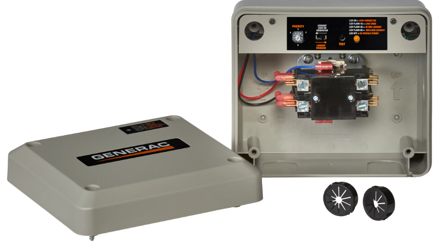
The Smart Management Modules (SMM) are designed to work together to prevent the home standby generator from being overloaded by large appliance loads. The modules require no control wires, and provide a cost effective, quick installation. Use of up to eight modules is available, allowing protection of your home and necessary appliances.
Detailed Specifications
The Generac Smart Management Module 006710 is a state-of-the-art power management system designed to optimize the performance of your home backup power. This module includes the following key features:
- 100 Amp, 12 circuit, load shed capable transfer switch
- Generac's innovative Smart Management technology
- Compatible with Generac PWR cell and other solar power systems
- Automatic exercise cycles to ensure readiness
- Easy-to-read LED indicators
- UL and CUL listed
Description
The Generac Smart Management Module 006710 is the perfect solution for homeowners seeking to maximize their backup power capabilities. By intelligently managing your power usage, this module ensures that your essential appliances and devices stay on during an outage, while less critical circuits are temporarily shut off. The Smart Management Module is compatible with Generac PWR cell and other solar power systems, allowing you to harness the full potential of your renewable energy sources. With its automatic exercise cycles and easy-to-read LED indicators, this module is both user-friendly and highly reliable.
General Information and Setup
Know Your Smart Management Module and Carton Contents
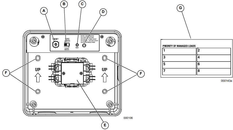
- Priority Dial (A): Sets module priority.
NOTE: PRIORITY MUST BE DIFFERENT for each module in an installation. Priority sets the order in which loads recover from a load shed event. Recovery time from a load shed event is five minutes for Priority 1. Each priority after Priority 1 waits an additional 15 seconds after the initial recovery time. See Table 1. - Lockout Switch (B): Prevents load from operating when system is operating under generator power. See Table 2.
NOTE: Recovery time is based on priority dial settings. See Table 1. - Test Button (C): Disables contactor output for a specified time.
- LED (D): Provides module status. See Table 3.
- Contactor (E): Controlled by a smart controller in module. Contactor remains CLOSED until generator power is required. Upon generator activation, controller moves to OPEN to handle overload conditions.
NOTE: The contactor is also opened during lockout switch ACTIVE state. - Mounting Holes (F): Internal enclosure mounting holes pro-vide clean and sturdy mounting.
- Priority Decal (G): Provided for recording priority of each module in installation. Should be installed on electrical panel.
Priority Dial Settings
Priority | Recovery Time |
1 | 5 minutes |
2 | 5 minutes 15 seconds |
3 | 5 minutes 30 seconds |
4 | 5 minutes 45 seconds |
5 | 6 minutes |
6 | 6 minutes 15 seconds |
7 | 6 minutes 30 seconds |
8 | 6 minutes 45 seconds |
9 | Not Used |
0 | Not Used |
Lockout Switch Settings
Lockout Switch Position |
Mode |
Function |
ON | GENERATOR | Power is NOT available on module output(contactor output). Contactor is OPEN. |
ON | UTILITY | Power is available on module output(contactor output). Contactor is CLOSED. |
OFF | GENERATOR | Module operates with standard loadshed logic. Contactor is OPEN or CLOSED perlogic. |
OFF | UTILITY | Power is available on module output(contactor output). Contactor is CLOSED. |
LED States
State | LED State | Mode | Note |
Shed | 1 second flash (1 On 1 Off) |
Generator | Module detected an overload and shed its load. This state only occurs in generator mode, or during a first time utility power up for five minutes of initial operation. |
Lockout (30minutes) |
3 second flash (3 On 3 Off) |
Generator | Module detected an overload while trying to recover from a shed situation. It identified the offending load and disabled operation for 30 minutes to allow other loads to operate. This state only occurs in generator mode. |
Lockout Switch Active | 6 second flash (6 On 6 Off) | Generator | Module output is disabled and there is no power to the appliance while in generator mode. Lockout switch must be ON. See Table2. |
Lockout Switch Active |
ON |
Utility | Lockout Switch operates in generator mode only. It has no function in utility mode. LED is solid, indicating contactor is CLOSED and load is connected. Lockout switch must be ON. See Table 2. |
Normal |
ON |
Generator or Utility | Indicates contactor is CLOSED and appliance has power. This is the default in utility mode. It is the normal operating state in generator mode when an overload is not detected. |
Test | 1 second flash | Generator or Utility | Test button triggers a typical shed condition and overrides all other states except generator lockout switch ACTIVE state. |
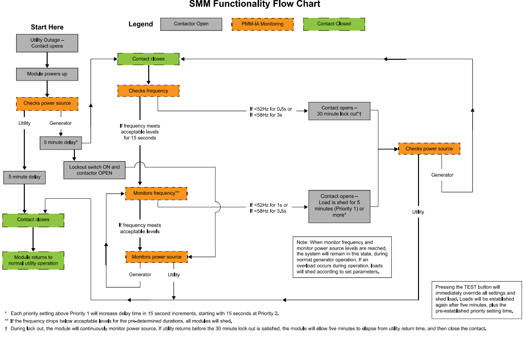
Sequence of Operations
Installation, Tests and Troubleshooting
Electrical Specifications
Input Voltage | 240 VAC |
Current Rating | 50A resistive, 40A inductive |
Locked Rotor Amp Rating | 240A |
Motor Rating | 3HP |
Contactor Coil Voltage | 240 VAC |
Enclosure Specifications
UL Rating | Type 3R |
Temperature | -30 to 50 deg C (-22to 122 deg F) |
Remove Contents from Carton
- Open carton.
- Remove and verify carton contents.
- Retain carton for mounting template.
Carton Contents- Smart Management Module (SMM)
- Priority decal
- Owner/Installation manual
- Contact the place of purchase with the unit model number for any missing carton contents.
- Record date of purchase on front cover of this manual.
Tools Needed For Installation
- Power drill and suitable drill bit
- Phillips and flat head screwdrivers
- Mounting screws or wall anchors
- Electrical materials
Mounting Instructions
The recommended installation is near the electrical panel or appliance/load. The enclosure has a UL type 3R rating and can be mounted indoors or outdoors. It provides a degree of protection against rain and sleet and is undamaged by the formation of ice on the enclosure.
- Turn OFF both UTILITY (NORMAL) and EMERGENCY (STANDBY) power supplies.
- Choose mounting location (near electrical panel, appliance or load to be managed).
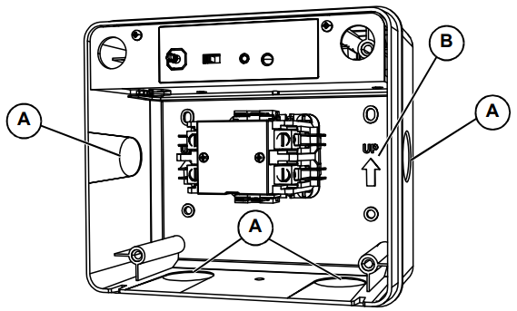
- Use a flat head screwdriver to remove appropriate knockouts from module enclosure for wiring. See A in Figure 3-1.
NOTE: If outdoor installation is chosen, bottom knockouts must be used to meet NEMA 3R rating and protect against water ingress. - Hold SMM enclosure against mounting surface with arrows pointing up, and mark or drill four mounting holes. See B in Figure 3-1 for arrows.
Install SMM enclosure to mounting surface using appropriate mounting screws or wall anchors.
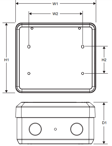
Mounting Dimensions
Height (in/mm) | H1 | 6.17/156.8 |
H2 | 2.36/60 | |
Width (in/mm) | W1 | 7.06/179.4 |
W2 | 4.72/120 | |
| Depth (in/mm) | D1 | 3.7/94 |
Generac Smart Management Module 006710 Connections
Wiring Diagram
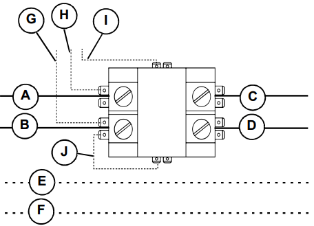
Legend | |
A | Red (240VAC - Line) |
B | Black (240VAC - Line) |
C | Red (240VAC - Load) |
D | Black (240 VAC - Load) |
E | White - Neutral (as required) |
F | Green - Ground (as required) |
G | Black - Factory (PCB) |
H | Red - Factory (PCB) |
I | Blue - Factory (PCB) |
J | Blue - Factory (Jumper) |
Turn OFF both UTILITY (NORMAL) and EMERGENCY (STANDBY) power supplies before connecting power source and load lines to transfer switch and SMM.
NOTE: Suitable conduit fittings must be installed in knockout openings when running supply and load wires.
NOTE: Use at least 75 ºC rated wire and gauge per installation instructions. Refer to table for recommended wire size based on load current.Temperature rating of conductor: 75 ºC (167ºF)
Conductor types (must be copper): RHW,THHW, THW, THWN, XHHW, USE, ZW
Size AWG
Maximum Current Rating
14
20A
12
25A
10
35A
8
50A
- Run line supply wires per applicable NEC code articles for wiring method selected.
- Run load wires per applicable NEC code articles for wiring method selected.
- Connect line supply wiring to line side of SMM contactor field terminals. See Figure 3-2. Tighten field terminals to 25 in-lbs (2.8 Nm).
- Connect load supply wiring to load side of SMM contactor field terminals. See Figure 3-2.
NOTE: If neutral and ground wires are included, connect inside SMM using a listed termination device. The unit is now ready to apply power and perform testing.
Setting Priorities
High priority 240 VAC loads should be set to the highest priorities so those loads recover first, in the event of generator overload.
NOTE: Setting priority determines timing for 3 scenarios:
- Order in which loads recover
- Delay time until power returns during an outage
- Delay time for post load shed recovery
An example configuration is shown below. Configurations will vary depending on customer prioritization of loads:
Priority
- Baseboard heat Priority
- Air conditioner Priority
- Range
- Dryer
- Non-essential circuits Priority
- Pool pump or hot tub Priority
- Other circuits Priority
- Other circuits
Set the priority
- Set the priority of each SMM module as desired (using the example configuration for reference).
- Apply priority decal in a suitable location on electrical panel to record chosen priority designations.
- Record priorities on decal.
Setting Lockout
Most installations will require the lockout switch will be DISABLED. When performing a whole house backup with a generator not sized to manage all household loads, SMM's can be used to disable appliances or circuits during an outage. For non-essential loads that will not be used on generator power, set lockout switch to ENABLED.
Tests
Utility Test
- 1. Turn utility power ON and enable all module feeding circuits.
- Verify LED begins to flash at one second intervals.
- All contactors will close after five minutes. LED will illuminate, and stay ON.
- Wait 30 seconds from power up then press TEST button and verify module load shed. LED will flash at one second intervals.
- Wait five minutes, plus predefined priority set time for module to recover.
- Contactor will CLOSE and LED will illuminate, and stay ON.
Generator Test
- Simulate a utility loss by turning main line circuit breaker (MLCB - service disconnect) to OFF while generator is in AUTO.
- All modules will lose power and LEDs will disable.
- Generator will power on after preset delay.
- All LEDs will flash when generator transfers.
- Allow each module to enable output per its priority set-ting.
- After predefined priority time elapses, each contactor will CLOSE and LED will illuminate and stay ON.
- Once LED stays ON, press TEST button and verify load shed occurs.
- Once load shed occurs, LED will flash at one second intervals.
- Allow time for each module to enable contactor output per priority setting.
- After predefined priority set time, each contactor will CLOSE and LED will illuminate and stay ON..
NOTE: Depending on load size, the SMM module may immediately go into load shed mode or lockout during test. In this event, remove one or more higher priority loads to allow testing of each module.
Generator Test with Lockout Switch Enabled
(perform if Lockout Switch Enabled on any loads)
- Simulate a utility loss by turning MLCB (service disconnect) to OFF while generator is in AUTO.
- All modules will lose power and LEDs will disable.
- Generator should power on after preset delay.
NOTE: For modules with lockout switch enabled, LEDs will flash at six second intervals and load will remain disabled while in generator power.
Return to Utility Test
- Return utility power by setting the MLCB (service disconnect) to ON.
NOTE: All modules should begin flashing at one second intervals.
NOTE: All modules will recover in five minutes (including units with lockout switch enabled).
Installation Summary
- Install cover on electrical panel.
- Install covers on modules.
Generac Smart Management Troubleshooting
Problem | Cause | Correction |
| Load not powered, LED is OFF | Circuit Breakerd isabled. | Enable Circuit Breaker |
| Load not powered, LED is OFF | MLCB disabled and generator OFF. | Enable MLCB if utility is present or verify generator operation if outage. |
Load not powered, LED flashing 1 second interval. | Generator power just applied to unit. Utility power just applied to unit. Generator was overloaded and shed occurred. | Wait 5 minutes plus the priority time delay (see Table 1) for unit to enable output. |
Load not powered, LED flashing 3 second interval. | This load overloaded the generator while attempting recovery from a shed. It is in a 30 minute lockout wait period. | Wait 30 minutes from lockout for unit to attempt to re-apply load. Review all loads enabled in household. The generator may end up in another overload condition when this load is enabled. Disable some loads to prevent generator overload from recurring. |
Load not powered, LED flashing 6 second interval. | The lockout switch is enabled and the unit is on generator power. | During installation, it was determined that this load will be disabled during generator operation to prevent generator overload. Contact servicing dealer for details. |
SMM module is humming. NOTE: A normal 60 Hz hum is expected from the normally open contactor. Excessive hum may be caused by one of the following: |
|
|
Pros & Cons
Pros
- Optimizes power usage during outages
- Compatible with Generac PWR cell and other solar power systems
- Automatic exercise cycles for reliability
- Easy-to-read LED indicators
- Load shed capable for added flexibility
Cons
- May require professional installation
- Limited to 12 circuits
- Higher cost compared to traditional transfer switches
Customer Reviews about Generac Smart Management Module 006710
Customers have praised the Generac Smart Management Module for its ease of use, seamless integration with solar systems, and reliable performance during power outages. However, some users have expressed concerns about the module's compatibility with certain appliances and the need for professional installation. The most common complaints revolve around the module's higher cost compared to traditional transfer switches and its limitation to 12 circuits.
Faqs
What is the Generac Smart Management Module and how does it work?
Is the Generac Smart Management Module compatible with solar power systems?
How many circuits can the Generac Smart Management Module manage?
Does the Generac Smart Management Module require professional installation?
How often does the Generac Smart Management Module perform automatic exercise cycles?
What is the warranty period for the Generac Smart Management Module?
Can the Generac Smart Management Module be used with a Generac whole-house generator?
How does the Generac Smart Management Module differ from a traditional transfer switch?
Can the Generac Smart Management Module manage 240-volt circuits?
What are the dimensions of the Generac Smart Management Module?
Leave a Comment