How to Install: Gigabyte Motherboard Gaming Z390
Content
Introduction
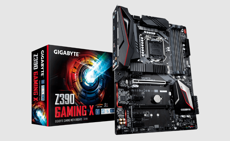
For power users and game lovers, Gigabyte created the high-performance Z390 Gaming motherboard. It has several PCIe extension slots, four DIMM slots that can hold up to 64GB of DDR4 RAM, and support for Intel Core 8th and 9th generation processors. It delivers strong performance and flexibility with support for NVMe SSDs, multi-GPU configurations, and cutting-edge cooling options. The motherboard is a great option for creating a robust and aesthetically pleasing gaming system because it also has configurable RGB lighting, a wide range of networking choices, and high-definition audio.
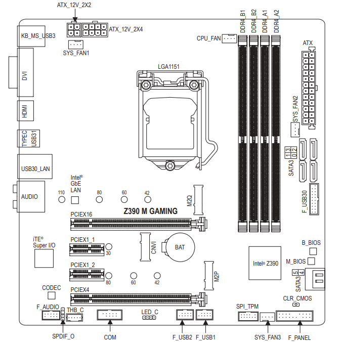
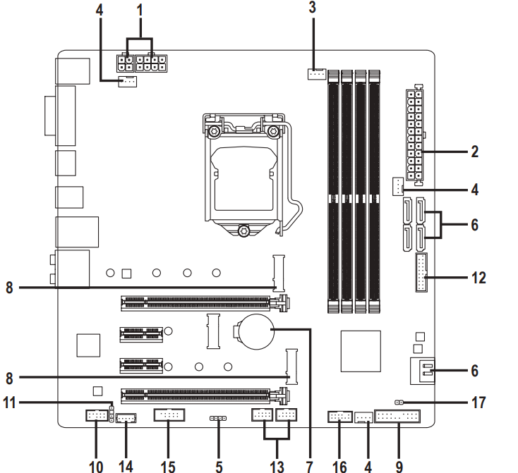
Z390 M GAMING Motherboard Layout
Box Contents
- Z390 M GAMING motherboard
- Motherboard driver disk
- User's Manual
- Two SATA cables
* The box contents above are for reference only and the actual items shall depend on the product package you obtain.
The box contents are subject to change without notice.
Product Specifications
CPU |
(Go to GIGABYTE's website for the latest CPU support list.)
|
|
|
Memory |
(Goto GIGABYTE's website for the latestsupported memory speedsand memory modules.) |
Onboard Graphics |
|
Audio |
|
|
|
Expansion Slots |
* For optimum performance, if only one PCI Express graphics card is to be installed, be sure to install it in the PCIEX16 slot.
(All of the PCI Express slots conform to PCI Express 3.0 standard.)
|
Multi-Graphics Technology |
|
Storage Interface Chipset:
x2 SSD support) (M2Q)
x4/x2 SSD support) (M2P)
* Refer to "1-7 Internal Connectors," for the installation notices for the M.2 and SATA connectors.
| |
USB |
the internal USB header)
|
Internal Connectors |
|
Back Panel Connectors |
|
|
|
Hardware Monitor |
* Whether the fan speed control function is supported will depend on the cooler you install. |
BIOS |
|
Unique Features |
* Available applications in APP Center may vary by motherboard model. Supported functions of each application may also varydepending on motherboard specifications.
|
Bundled Software |
|
Operating System |
|
|
|
GIGABYTE reserves the right to make any changes to the product specifications and product-related information without prior notice.
Hardware Installation
Installation Precautions
The motherboard contains numerous delicate electronic circuits and components which can become damaged as a result of electrostatic discharge (ESD). Prior to installation, carefully read the user's manual and follow these procedures:
- Prior to installation, make sure the chassis is suitable for the motherboard.
- Prior to installation, do not remove or break motherboard S/N (Serial Number) sticker or warranty sticker provided by your dealer. These stickers are required for warranty validation.
- Always remove the AC power by unplugging the power cord from the power outlet before installing or removing the motherboard or other hardware components.
- When connecting hardware components to the internal connectors on the motherboard, make sure they are connected tightly and securely.
- When handling the motherboard, avoid touching any metal leads or connectors.
- It is best to wear an electrostatic discharge (ESD) wrist strap when handling electronic components such as a motherboard, CPU or memory. If you do not have an ESD wrist strap, keep your hands dry and first touch a metal object to eliminate static electricity.
- Prior to installing the motherboard, please have it on top of an antistatic pad or within an electrostatic shielding container.
- Before connecting or unplugging the power supply cable from the motherboard, make sure the power supply has been turned off.
- Before turning on the power, make sure the power supply voltage has been set according to the local voltage standard.
- Before using the product, please verify that all cables and power connectors of your hardware components are connected.
- To prevent damage to the motherboard, do not allow screws to come in contact with the motherboard circuit or its components.
- Make sure there are no leftover screws or metal components placed on the motherboard or within the computer casing.
- Do not place the computer system on an uneven surface.
- Do not place the computer system in a high-temperature or wet environment.
- Turning on the computer power during the installation process can lead to damage to system components as well as physical harm to the user.
- If you are uncertain about any installation steps or have a problem related to the use of the product, please consult a certified computer technician.
- If you use an adapter, extension power cable, or power strip, ensure to consult with its installation and/or grounding instructions.
Installing the CPU
Read the following guidelines before you begin to install the CPU:
- Make sure that the motherboard supports the CPU. (Go to GIGABYTE's website for the latest CPU support list.)
- Always turn off the computer and unplug the power cord from the power outlet before installing the CPU to prevent hardware damage.
- Locate the pin one of the CPU. The CPU cannot be inserted if oriented incorrectly. (Or you may locate the notches on both sides of the CPU and alignment keys on the CPU socket.)
- Apply an even and thin layer of thermal grease on the surface of the CPU.
- Do not turn on the computer if the CPU cooler is not installed, otherwise overheating and damage of the CPU may occur.
- Set the CPU host frequency in accordance with the CPU specifications. It is not recommended that the system bus frequency be set beyond hardware specifications since it does not meet the standard requirements for the peripherals. If you wish to set the frequency beyond the standard specifications, please do so according to your hardware specifications including the CPU, graphics card, memory, hard drive, etc.
Locate the alignment keys on the motherboard CPU socket and the notches on the CPU.
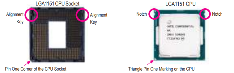
WARNING: Do not remove the CPU socket cover before inserting the CPU. It may pop off from the load plate automatically during the process of re-engaging the lever after you insert the CPU.
Installing the Memory
Read the following guidelines before you begin to install the memory:
- Make sure that the motherboard supports the memory. It is recommended that memory of the same capacity, brand, speed, and chips be used. (Go to GIGABYTE's website for the latest supported memory speeds and memory modules.)
- Always turn off the computer and unplug the power cord from the power outlet before installing the memory to prevent hardware damage.
- Memory modules have a foolproof design. A memory module can be installed in only one direction. If you are unable to insert the memory, switch the direction.
Dual Channel Memory Configuration
This motherboard provides four memory sockets and supports Dual Channel Technology. After the memory is installed, the BIOS will automatically detect the specifications and capacity of the memory. Enabling Dual Channel memory mode will double the original memory bandwidth.
The four memory sockets are divided into two channels and each channel has two memory sockets as following:
- Channel A: DDR4_A1, DDR4_A2
- Channel B: DDR4_B1, DDR4_B2
Dual Channel Memory Configurations Table
DDR4_B1 | DDR4_B2 | DDR4_A1 | DDR4_A2 | |
DS/SS | - - | DS/SS | - - | |
2 Modules | - - | DS/SS | - - | DS/SS |
4 Modules | DS/SS | DS/SS | DS/SS | DS/SS |
(SS=Single-Sided, DS=Double-Sided, "- -"=No Memory)
Due to CPU limitations, read the following guidelines before installing the memory in Dual Channel mode.
- Dual Channel mode cannot be enabled if only one memory module is installed.
- When enabling Dual Channel mode with two or four memory modules, it is recommended that memory of the same capacity, brand, speed, and chips be used.
Installing an Expansion Card
Read the following guidelines before you begin to install an expansion card:
- Make sure the motherboard supports the expansion card. Carefully read the manual that came with your expansion card.
- Always turn off the computer and unplug the power cord from the power outlet before installing an expansion card to prevent hardware damage.
Back Panel Connectors
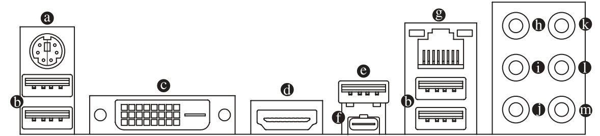
- PS/2 Keyboard/Mouse Port
Use this port to connect a PS/2 mouse or keyboard. - USB 3.1 Gen 1 Port
The USB 3.1 Gen 1 port supports the USB 3.1 Gen 1 specification and is compatible to the USB 2.0 specification. Use this port for USB devices. - DVI-D Port (Note)
The DVI-D port conforms to the DVI-D specification and supports a maximum resolution of 1920x1200@60 Hz (the actual resolutions supported depend on the monitor being used). Connect a monitor that supports DVI-D connection to this port. - HDMI Port
The HDMI port supports HDCP 2.2 and Dolby TrueHD and DTS HD Master Audio formats. It also supports up to 192KHz/16bit 8-channel LPCM audio output. You can use this port to connect your HDMI-supported monitor. The maximum supported resolution is 4096x2160@30 Hz, but the actual resolutions supported are dependent on the monitor being used. - USB 3.1 Gen 2 Type-A Port (Red)
The USB 3.1 Gen 2 Type-A port supports the USB 3.1 Gen 2 specification and is compatible to the USB 3.1 Gen 1 and USB 2.0 specification. Use this port for USB devices. - USB Type-C Port
The reversible USB port supports the USB 3.1 Gen 2 specification and is compatible to the USB 3.1 Gen 1 and USB 2.0 specification. Use this port for USB devices. RJ-45 LAN Port
The Gigabit Ethernet LAN port provides Internet connection at up to 1 Gbps data rate. The following describes the states of the LAN port LEDs.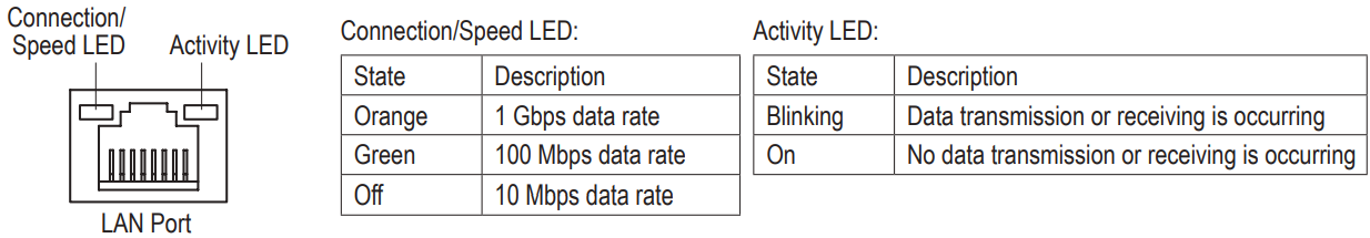
- Center/Subwoofer Speaker Out (Orange)
Use this audio jack to connect center/subwoofer speakers in a 5.1/7.1-channel audio configuration. - Rear Speaker Out (Black)
This jack can be used to connect rear speakers in a 4/5.1/7.1-channel audio configuration. - Side Speaker Out (Gray)
Use this audio jack to connect side speakers in a 7.1-channel audio configuration. - Line In (Blue)
The line in jack. Use this audio jack for line in devices such as an optical drive, walkman, etc. - Line Out (Green)
The line out jack. - Mic In (Pink)
The Mic in jack.
Audio Jack Configurations
Jack | Headphone/ 2-channel | 4-channel | 5.1-channel | 7.1-channel |
Center/Subwoofer Speaker Out |
|
| ||
Rear Speaker Out |
|
|
| |
Side Speaker Out |
| |||
Line In | ||||
Line Out/Front Speaker Out |
|
|
|
|
Mic In |
When removing the cable connected to a back panel connector, first remove the cable from your device and then remove it from the motherboard
When removing the cable, pull it straight out from the connector. Do not rock it side to side to prevent an electrical short inside the cable connector.
Description
Gigabyte Motherboard Gaming Z390 is a high-performing motherboard designed to be compatible with Intel Core processors of the 8th and 9th generations. The motherboard features a streamlined appearance and incorporates RGB Fusion technology, enabling users to personalize the lighting according to their preferences. This motherboard is equipped with built-in Wi-Fi, allowing for convenient internet connectivity without requiring any additional gear. The system is compatible with DDR4 RAM that supports XMP up to 4400MHz. Additionally, it is equipped with dual PCIe x16 slots specifically designed for graphics cards. The Smart Fan 5 technology guarantees optimal cooling and noise reduction for your system, even when it is subjected to high workloads.
Internal Connectors
- ATX_12V_2X2/ATX_12V_2X4
- ATX
- CPU_FAN
- SYS_FAN1/2/3
- LED_C
- SATA3 0/1/2/3/4/5
- BAT
- M2Q/M2P
- F_PANEL
- F_AUDIO
- SPDIF_O
- F_USB30
- F_USB1/F_USB2
- THB_C
- COM
- SPI_TPM
- CLR_CMOS
Read the following guidelines before connecting external devices:
- First make sure your devices are compliant with the connectors you wish to connect.
- Before installing the devices, be sure to turn off the devices and your computer. Unplug the power cord from the power outlet to prevent damage to the devices.
- After installing the device and before turning on the computer, make sure the device cable has been securely attached to the connector on the motherboard.
1/2) ATX_12V_2X2/ATX_12V_2X4/ATX (2x2, 2x4, 12V Power Connectors and 2x12 Main Power Connector)
With the use of the power connector, the power supply can supply enough stable power to all the components on the motherboard. Before connecting the power connector, first make sure the power supply is turned off and all devices are properly installed. The power connector possesses a foolproof design. Connect the power supply cable to the power connector in the correct orientation.
The 12V power connector mainly supplies power to the CPU. If the 12V power connector is not connected, the computer will not start.
To meet expansion requirements, it is recommended that a power supply that can withstand high power consumption be used (500W or greater). If a power supply is used that does not provide the required power, the result can lead to an unstable or unbootable system.
ATX_12V_2X2:
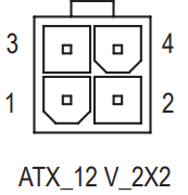
Pin No. | Definition |
1 | GND |
2 | GND |
3 | +12V |
4 | +12V |
ATX_12V_2X4:
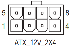
Pin No. | Definition | Pin No. | Definition |
1 | GND (Only for 2x4-pin 12V) | 5 | +12V (Only for 2x4-pin 12V) |
2 | GND (Only for 2x4-pin 12V) | 6 | +12V (Only for 2x4-pin 12V) |
3 | GND | 7 | +12V |
4 | GND | 8 | +12V |
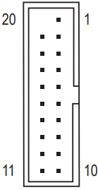
ATX:
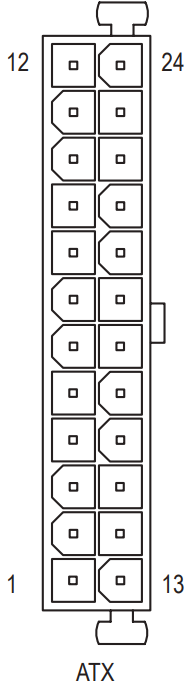
Pin No. | Definition | Pin No. | Definition |
1 | 3.3V | 13 | 3.3V |
2 | 3.3V | 14 | -12V |
3 | GND | 15 | GND |
4 | +5V | 16 | PS_ON (soft On/Off) |
5 | GND | 17 | GND |
6 | +5V | 18 | GND |
7 | GND | 19 | GND |
8 | Power Good | 20 | NC |
9 | 5VSB (stand by +5V) | 21 | +5V |
10 | +12V | 22 | +5V |
11 | +12V (Only for 2x12-pin ATX) | 23 | +5V (Only for 2x12-pin ATX) |
12 | 3.3V (Only for 2x12-pin ATX) | 24 | GND(Only for 2x12-pin ATX) |
CPU_FAN/SYS_FAN1/2/3 (Fan Headers)
All fan headers on this motherboard are 4-pin. Most fan headers possess a foolproof insertion design. When connecting a fan cable, be sure to connect it in the correct orientation (the black connector wire is the ground wire). The speed control function requires the use of a fan with fan speed control design. For optimum heat dissipation, it is recommended that a system fan be installed inside the chassis.
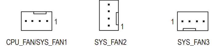
Pin No. | Definition |
1 | GND |
2 | Voltage Speed Control |
3 | Sense |
4 | PWM Speed Control |
WARNING: Be sure to connect fan cables to the fan headers to prevent your CPU and system from overheating. Overheating may result in damage to the CPU or the system may hang. These fan headers are not configuration jumper blocks. Do not place a jumper cap on the headers.
LED_C (RGB LED Strip Header)
The header can be used to connect a standard 5050 RGB LED strip (12V/G/R/B), with maximum power rating of 2A (12V) and maximum length of 2m.
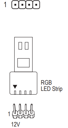
Pin No. | Definition |
1 | 12V |
2 | G |
3 | R |
4 | B |
Connect your RGB LED strip to the header. The power pin (marked with a triangle on the plug) of the LED strip must be connected to Pin 1 (12V) of this header. Incorrect connection may lead to the damage of the LED strip.
TIP: For how to turn on/off the lights of the LED strip please visit the "Unique Features" webpage of GIGABYTE's website.
WARNING: Before installing the devices, be sure to turn off the devices and your computer. Unplug the power cord from the power outlet to prevent damage to the devices.
SATA3 0/1/2/3/4/5 (SATA 6Gb/s Connectors)
The SATA connectors conform to SATA 6Gb/s standard and are compatible with SATA 3Gb/s and SATA 1.5Gb/s standard. Each SATA connector supports a single SATA device. The Intel® Chipset supports RAID 0, RAID 1, RAID 5, and RAID 10. Refer to Chapter 3, "Configuring a RAID Set," for instructions on configuring a RAID array.
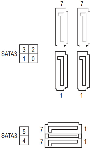
Pin No. | Definition |
1 | GND |
2 | TXP |
3 | TXN |
4 | GND |
5 | RXN |
6 | RXP |
7 | GND |
To enable hot-plugging for the SATA ports, refer to Chapter 2, "BIOS Setup," "Peripherals\SATA And RST Configuration," for more information.
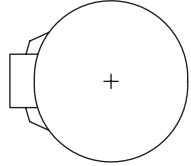
BAT (Battery)
The battery provides power to keep the values (such as BIOS configurations, date, and time information) in the CMOS when the computer is turned off. Replace the battery when the battery voltage drops to a low level, or the CMOS values may not be accurate or may be lost.
You may clear the CMOS values by removing the battery:
- Turn off your computer and unplug the power cord.
- Gently remove the battery from the battery holder and wait for one minute. (Or use a metal object like a screwdriver to touch the positive and negative terminals of the battery holder, making them short for 5 seconds.)
- Replace the battery.
- Plug in the power cord and restart your computer.
- Always turn off your computer and unplug the power cord before replacing the battery.
- Replace the battery with an equivalent one. Damage to your devices may occur if the battery is replaced with an incorrect model.
- Contact the place of purchase or local dealer if you are not able to replace the battery by yourself or uncertain about the battery model.
- When installing the battery, note the orientation of the positive side (+) and the negative side (-) of the battery (the positive side should face up).
Used batteries must be handled in accordance with local environmental regulations.
M2Q/M2P (M.2 Socket 3 Connectors)
The M.2 connectors support M.2 SATA SSDs or M.2 PCIe SSDs and support RAID configuration. Please note that an M.2 PCIe SSD cannot be used to create a RAID set either with an M.2 SATA SSD or a SATA hard drive. To create a RAID array with an M.2 PCIe SSD, you must set up the configuration in UEFI BIOS mode. Refer to Chapter 3, "Configuring a RAID Set," for instructions on configuring a RAID array.
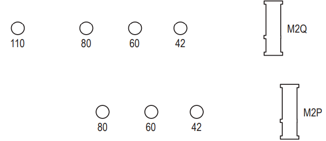
Follow the steps below to correctly install an M.2 SSD in the M.2 connector.
- Step 1: Use a crew driver to unfasten the screw and standoff from the motherboard. Locate the proper mounting hole for the M.2 SSD to be installed and then screw the standoff first.
- Step 2: Slide the M.2 SSD into the connector at an angle.
- Step 3: Press the M.2 SSD down and then secure it with the screw.
Select the proper hole for the M.2 SSD to be installed and refasten the screw and standoff.
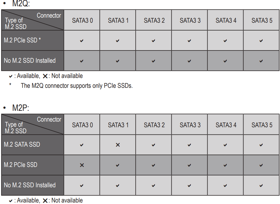
Installation Notices for the M.2 and SATA Connectors:
Due to the limited number of lanes provided by the Chipset, the availability of the SATA connectors may be affected by the type of device installed in the M.2 connector. The M2P connector shares bandwidth with the SATA3 0,1 connector. Refer to the following table for details.
F_PANEL (Front Panel Header)
Connect the power switch, reset switch, speaker, chassis intrusion switch/sensor and system status indicator on the chassis to this header according to the pin assignments below. Note the positive and negative pins before connecting the cables.
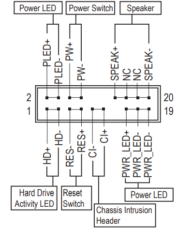
PLED/PWR_LED (Power LED, Yellow/Purple): Connects to the power status indicator on the chassis front panel. The LED is on when the system is operating. The LED is off when the system is in S3/S4 sleep state or powered off (S5).
System Status
LED
S0
On
S3/S4/S5
Off
- PW (Power Switch, Red): Connects to the power switch on the chassis front panel. You may configure the way to turn off your system using the power switch (refer to Chapter 2, "BIOS Setup," "Power," for more information).
- SPEAK (Speaker, Orange): Connects to the speaker on the chassis front panel. The system reports system startup status by issuing a beep code. One single short beep will be heard if no problem is detected at system startup.
- HD (Hard Drive Activity LED, Blue): Connects to the hard drive activity LED on the chassis front panel. The LED is on when the hard drive is reading or writing data.
- RES (Reset Switch, Green): Connects to the reset switch on the chassis front panel. Press the reset switch to restart the computer if the computer freezes and fails to perform a normal restart.
- CI (Chassis Intrusion Header, Gray): Connects to the chassis intrusion switch/sensor on the chassis that can detect if the chassis cover has been removed. This function requires a chassis with a chassis intrusion switch/sensor.
- NC (Orange): No Connection.
TIP: The front panel design may differ by chassis. A front panel module mainly consists of power switch, reset switch, power LED, hard drive activity LED, speaker and etc. When connecting your chassis front panel module to this header, make sure the wire assignments and the pin assignments are matched correctly.
F_AUDIO (Front Panel Audio Header)
The front panel audio header supports High Definition audio (HD). You may connect your chassis front panel audio module to this header. Make sure the wire assignments of the module connector match the pin assignments of the motherboard header. Incorrect connection between the module connector and the motherboard header will make the device unable to work or even damage it.
Pin No. | Definition | Pin No. | Definition |
1 | MIC2_L | 6 | Sense |
2 | GND | 7 | FAUDIO_JD |
3 | MIC2_R | 8 | No Pin |
4 | NC | 9 | LINE2_L |
5 | LINE2_R | 10 | Sense |
Some chassis provide a front panel audio module that has separated connectors on each wire instead of a single plug. For information about connecting the front panel audio module that has different wire assignments, please contact the chassis manufacturer.
SPDIF_O (S/PDIF Out Header)
This header supports digital S/PDIF Out and connects a S/PDIF digital audio cable (provided by expansion cards) for digital audio output from your motherboard to certain expansion cards like graphics cards and sound cards. For example, some graphics cards may require you to use a S/PDIF digital audio cable for digital audio output from your motherboard to your graphics card if you wish to connect an HDMI display to the graphics card and have digital audio output from the HDMI display at the same time. For information about connecting the S/PDIF digital audio cable, carefully read the manual for your expansion card.

Pin No. | Definition |
1 | 5VDUAL |
2 | No Pin |
3 | SPDIFO |
4 | GND |
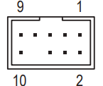
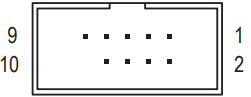
F_USB30 (USB 3.1 Gen 1 Header)
The header conforms to USB 3.1 Gen 1 and USB 2.0 specification and can provide two USB ports. For purchasing the optional 3.5" front panel that provides two USB 3.1 Gen 1 ports, please contact the local dealer.
Pin No. | Definition | Pin No. | Definition | Pin No. | Definition |
1 | VBUS | 8 | D1- | 15 | SSTX2- |
2 | SSRX1- | 9 | D1+ | 16 | GND |
3 | SSRX1+ | 10 | NC | 17 | SSRX2+ |
4 | GND | 11 | D2+ | 18 | SSRX2- |
5 | SSTX1- | 12 | D2- | 19 | VBUS |
6 | SSTX1+ | 13 | GND | 20 | No Pin |
7 | GND | 14 | SSTX2+ |
WARNING: Prior to installing the USB bracket, be sure to turn off your computer and unplug the power cord from the power outlet to prevent damage to the USB bracket.
F_USB1/F_USB2 (USB 2.0/1.1 Headers)
The headers conform to USB 2.0/1.1 specification. Each USB header can provide two USB ports via an optional USB bracket. For purchasing the optional USB bracket, please contact the local dealer.
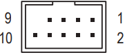
Pin No. | Definition | Pin No. | Definition |
1 | Power (5V) | 6 | USB DY+ |
2 | Power (5V) | 7 | GND |
3 | USB DX- | 8 | GND |
4 | USB DY- | 9 | No Pin |
5 | USB DX+ | 10 | NC |
WARNING: Do not plug the IEEE 1394 bracket (2x5-pin) cable into the USB 2.0/1.1 header. Prior to installing the USB bracket, be sure to turn off your computer and unplug the power cord from the power outlet to prevent damage to the USB bracket.
THB_C (Thunderbolt Add-in Card Connector)
This connector is for a GIGABYTE Thunderbolt add-in card.
Pin No. | Definition | Pin No. | Definition |
1 | NDCD- | 6 | NDSR- |
2 | NSIN | 7 | NRTS- |
3 | NSOUT | 8 | NCTS- |
4 | NDTR- | 9 | NRI- |
5 | GND | 10 | No Pin |
Supports a Thunderbolt add-in card.
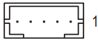
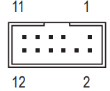
COM (Serial Port Header)
The COM header can provide one serial port via an optional COM port cable. For purchasing the optional COM port cable, please contact the local dealer.
Pin No. | Definition | Pin No. | Definition |
1 | Data Output | 7 | Chip Select |
2 | Power (3.3V) | 8 | GND |
3 | No Pin | 9 | IRQ |
4 | NC | 10 | NC |
5 | Data Input | 11 | NC |
6 | CLK | 12 | RST |
SPI_TPM (Trusted Platform Module Header)
You may connect an SPI TPM (Trusted Platform Module) to this header.
CLR_CMOS (Clear CMOS Jumper)
Use this jumper to clear the BIOS configuration and reset the CMOS values to factory defaults. To clear the CMOS values, use a metal object like a screwdriver to touch the two pins for a few seconds.
WARNING: Always turn off your computer and unplug the power cord from the power outlet before clearing the CMOS values. After system restart, go to BIOS Setup to load factory defaults (select Load Optimized Defaults) or manually configure the BIOS settings (refer to Chapter 2, "BIOS Setup," for BIOS configurations).

BIOS Setup
BIOS (Basic Input and Output System) records hardware parameters of the system in the CMOS on the motherboard. Its major functions include conducting the Power-On Self-Test (POST) during system startup, saving system parameters and loading the operating system, etc. BIOS includes a BIOS Setup program that allows the user to modify basic system configuration settings or to activate certain system features. When the power is turned off, the battery on the motherboard supplies the necessary power to the CMOS to keep the configuration values in the CMOS. To access the BIOS Setup program, press the <Delete> key during the POST when the power is turned on. To upgrade the BIOS, use either the GIGABYTE Q-Flash or @BIOS utility.
- Q-Flash allows the user to quickly and easily upgrade or back up BIOS without entering the operating system.
- @BIOS is a Windows-based utility that searches and downloads the latest version of BIOS from the Internet and updates the BIOS.
- Because BIOS flashing is potentially risky, if you do not encounter problems using the current version of BIOS, it is recommended that you not flash the BIOS. To flash the BIOS, do it with caution. Inadequate BIOS flashing may result in system malfunction.
- It is recommended that you not alter the default settings (unless you need to) to prevent system instability or other unexpected results. Inadequately altering the settings may result in the system's failure to boot. If this occurs, try to clear the CMOS values and reset the board to default values. (Refer to the "Load Optimized Defaults" section in this chapter or introductions of the battery/clear CMOS jumper in Chapter 1 for how to clear the CMOS values.)
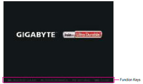
Startup Screen
The following startup Logo screen will appear when the computer boots.(Sample BIOS Version: E1)
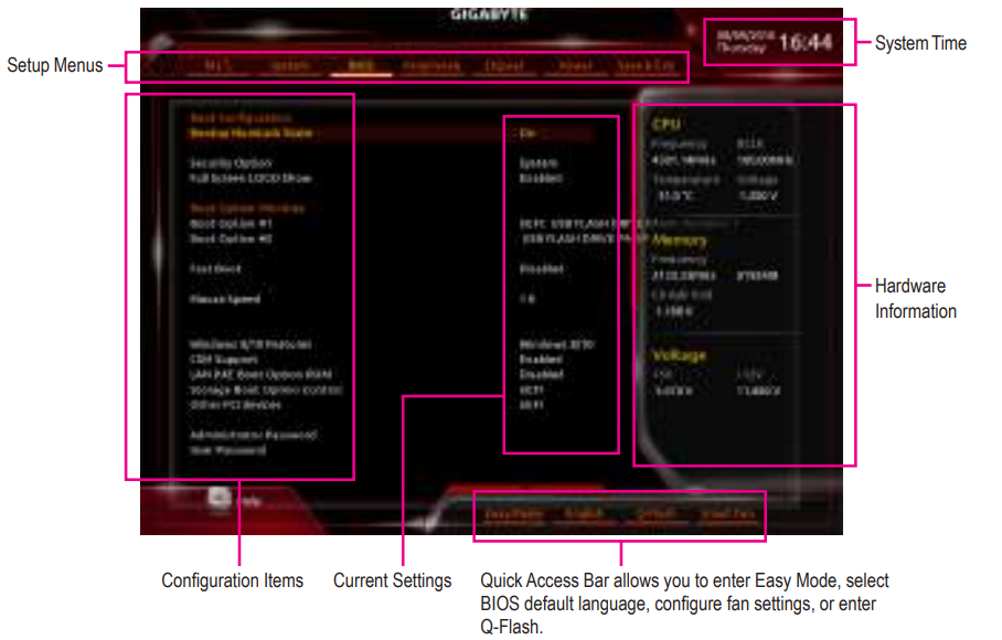
There are two different BIOS modes as follows, and you can use the <F2> key to switch between the two modes. The Classic Setup mode provides detailed BIOS settings. You can press the arrow keys on your keyboard to move among the items and press <Enter> to accept or enter a sub-menu. Or you can use your mouse to select the item you want. Easy Mode allows users to quickly view their current system information or to make adjustments for optimum performance. In Easy Mode, you can use your mouse to move through configuration items.
Main Menu
Classic Setup Function Keys
| Key | Function |
|---|---|
| <←→><↑↓> | Move the selection bar to select a setup menu |
| <T><L> | Move the selection bar to select a configuration item on a menu |
| <Enter> | Execute command or enter a menu |
| <+>/ <Page Up> | Increase the numeric value or make changes |
| <->/ <Page Down> | Decrease the numeric value or make changes |
| <F1> | Show descriptions of the function keys |
| <F2> | Switch to Easy Mode |
| <F5> | Restore the previous BIOS settings for the current submenu |
| <F7> | Load the Optimized BIOS default settings for the current submenu |
| <F8> | Access the Q-Flash utility |
| <F9> | Display system information |
| <F10> | Save all the changes and exit the BIOS Setup program |
| <F12> | Capture the current screen as an image and save it to your USB drive |
| <Esc> | Main Menu: Exit the BIOS Setup program Submenus: Exit current submenu |
M.I.T.
Whether the system will work stably with the overclock/overvoltage settings you made is dependent on your overall system configurations. Incorrectly doing overclock/overvoltage may result in damage to the CPU, chipset, or memory and reduce the useful life of these components. This page is for advanced users only and we recommend you not to alter the default settings to prevent system instability or other unexpected results. (Inadequately altering the settings may result in the system's failure to boot. If this occurs, clear the CMOS values and reset the board to default values.)
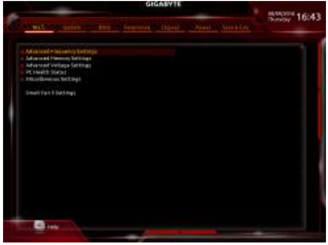
Advanced Frequency Settings
- CPU Base Clock
Allows you to manually set the CPU base clock in 0.01 MHz increments. (Default: Auto) Important: It is highly recommended that the CPU frequency be set in accordance with the CPU specifications. - Host Clock Value
This value changes with the CPU Base Clock setting. - Graphics Slice Ratio
(Note)
Allows you to set the Graphics Slice Ratio. - Graphics UnSlice Ratio
(Note) Allows you to set the Graphics UnSlice Ratio. - CPU Upgrade
(Note) Allows you to set the CPU frequency. Options may vary depending on the CPU being used. (Default: Auto) - Enhanced Multi-Core Performance
Determines whether to allow the CPU to run at Turbo 1C speed. Auto lets the BIOS automatically configure this setting. (Default: Auto) - CPU Clock Ratio
Allows you to alter the clock ratio for the installed CPU. The adjustable range is dependent on the CPU being installed. - CPU Frequency
Displays the current operating CPU frequency. - (Note) This item is present only when you install a CPU that supports this feature. For more information about Intel® CPUs' unique features, please visit Intel's website.
- FCLK Frequency for Early Power On
Allows you to set the FCLK frequency. Options are: Normal(800Mhz), 1GHz, 400MHz. (Default: 1GHz)
Advanced CPU Core Settings
- CPU Clock Ratio, CPU Frequency, FCLK Frequency for Early Power On
The settings above are synchronous to those under the same items on the Advanced Frequency Settings menu. - AVX Offset
(Note): AVX offset is the negative offset of AVX ratio. - TJ-Max Offset
(Note): Allows you to fine-tune the TJ Max offset value. (Default: Auto) - Uncore Ratio
Allows you to set the CPU Uncore ratio. The adjustable range is dependent on the CPU being used. - Uncore Frequency
Displays the current CPU Uncore frequency. - CPU Flex Ratio Override
Enables or disables the CPU Flex Ratio. The maximum CPU clock ratio will be based on the CPU Flex Ratio Settings value if CPU Clock Ratio is set to Auto. (Default: Disabled) - CPU Flex Ratio Settings
Allows you to set the CPU Flex Ratio. The adjustable range may vary by CPU. - Intel(R) Turbo Boost Technology
(Note): Allows you to determine whether to enable the Intel CPU Turbo Boost technology. Auto lets the BIOS automatically configure this setting. (Default: Auto) - Turbo Ratio
(Note): Allows you to set the CPU Turbo ratios for different numbers of active cores. Auto sets the CPU Turbo ratios according to the CPU specifications. (Default: Auto) - Power Limit TDP (Watts) / Power Limit Time
Allows you to set the power limit for CPU Turbo mode and how long it takes to operate at the specified power limit. If the specified value is exceeded, the CPU will automatically reduce the core frequency to reduce the power. Auto sets the power limit according to the CPU specifications. (Default: Auto) - Core Current Limit (Amps)
Allows you to set a current limit for CPU Turbo mode. When the CPU current exceeds the specified current limit, the CPU will automatically reduce the core frequency to reduce the current. Auto sets the power limit according to the CPU specifications. (Default: Auto) - Turbo Per Core Limit Control
(Note): Allows you to control each CPU core limit separately. (Default: Auto) - No. of CPU Cores Enabled
(Note): Allows you to select the number of CPU cores to enable in an Intel® multi-core CPU (the number of CPU cores may vary by CPU). Auto lets the BIOS automatically configure this setting. (Default: Auto) - Hyper-Threading Technology
(Note): Allows you to determine whether to enable multi-threading technology when using an Intel® CPU that supports this function. This feature only works for operating systems that support multi-processor mode. Auto lets the BIOS automatically configure this setting. (Default: Auto)
Intel(R) Speed Shift Technology
(Intel Speed Shift Technology)
(Note) Enables or disables Intel Speed Shift Technology. Enabling this feature allows the processor to ramp up its operating frequency more quickly and then improves the system responsiveness. (Default: Auto)
- CPU Enhanced Halt (C1E)
(Note): Enables or disables Intel CPU Enhanced Halt (C1E) function, a CPU power-saving function in the system halt state. When enabled, the CPU core frequency and voltage will be reduced during system halt state to decrease power consumption. Auto lets the BIOS automatically configure this setting. (Default: Auto) - C3 State Support
(Note): Allows you to determine whether to let the CPU enter C3 mode in system halt state. When enabled, the CPU core frequency and voltage will be reduced during system halt state to decrease power consumption. The C3 state is a more enhanced power-saving state than C1. Auto lets the BIOS automatically configure this setting. (Default: Auto) - C6/C7 State Support
(Note): Allows you to determine whether to let the CPU enter C6/C7 mode in system halt state. When enabled, the CPU core frequency and voltage will be reduced during system halt state to decrease power consumption. The C6/C7 state is a more enhanced power-saving state than C3. Auto lets the BIOS automatically configure this setting. (Default: Auto) - C8 State Support
(Note): Allows you to determine whether to let the CPU enter C8 mode in system halt state. When enabled, the CPU core frequency and voltage will be reduced during system halt state to decrease power consumption. The C8 state is a more enhanced power-saving state than C6/C7. Auto lets the BIOS automatically configure this setting. (Default: Auto) - C10 State Support
(Note): Allows you to determine whether to let the CPU enter C10 mode in system halt state. When enabled, the CPU core frequency and voltage will be reduced during system halt state to decrease power consumption. The C10 state is a more enhanced power-saving state than C8. Auto lets the BIOS automatically configure this setting. (Default: Auto) - Package C State Limit
(Note): Allows you to specify the C-state limit for the processor. Auto lets the BIOS automatically configure this setting. (Default: Auto) - CPU Thermal Monitor
(Note): Enables or disables Intel Thermal Monitor function, a CPU overheating protection function. When enabled, the CPU core frequency and voltage will be reduced when the CPU is overheated. Auto lets the BIOS automatically configure this setting. (Default: Auto) - Ring to Core offset (Down Bin)
Allows you to determine whether to disable the CPU Ring ratio auto-down function. Auto lets the BIOS automatically configure this setting. (Default: Auto) - CPU EIST Function
(Note): Enables or disables Enhanced Intel Speed Step Technology (EIST). Depending on CPU loading, Intel EIST technology can dynamically and effectively lower the CPU voltage and core frequency to decrease average power consumption and heat production. Auto lets the BIOS automatically configure this setting. (Default: Auto) - Race To Halt (RTH) (Note)/Energy Efficient Turbo
(Note): Enables or disables the CPU power saving related settings. - Voltage Optimization
Allows you to determine whether to enable voltage optimization to reduce power consumption. (Default: Auto)
Hardware Prefetcher
Allows you to determine whether to enable hardware prefetcher to prefetch data and instructions from the memory into the cache. (Default: Auto)
- Adjacent Cache Line Prefetch
Allows you to determine whether to enable the adjacent cache line prefetch mechanism that lets the processor retrieve the requested cache line as well as the subsequent cache line. (Default: Auto) - Extreme Memory Profile (X.M.P.)
(Note): Allows the BIOS to read the SPD data on XMP memory module(s) to enhance memory performance when enabled.- Disabled: Disables this function. (Default)
- Profile 1: Uses Profile 1 settings.
- Profile2 (Note): Uses Profile 2 settings.
- System Memory Multiplier: Allows you to set the system memory multiplier. Auto sets memory multiplier according to memory SPD data. (Default: Auto)
- Memory Ref Clock: Allows you to manually adjust the memory reference clock. (Default: Auto)
- Memory Odd Ratio (100/133 or 200/266): Enabled allows Qclk to run in odd frequency. (Default: Auto)
- Memory Frequency (MHz): The first memory frequency value is the normal operating frequency of the memory being used; the second is the memory frequency that is automatically adjusted according to the System Memory Multiplier settings.
Advanced Memory Settings
- Extreme Memory Profile (X.M.P.)
(Note), System Memory Multiplier,
Memory Ref Clock, Memory Odd Ratio (100/133 or 200/266),
Memory Frequency (MHz): The settings above are synchronous to those under the same items on the Advanced Frequency Settings menu. - Memory Boot Mode
(Note): Provides memory detection and training methods.- Auto: Lets the BIOS automatically configure this setting. (Default)
- Normal: The BIOS automatically performs memory training. Please note that if the system becomes unstable or unbootable, try to clear the CMOS values and reset the board to default values. (Refer to the introductions of the battery/clear CMOS jumper in Chapter 1 for how to clear the CMOS values.)
- Enable Fast Boot: Skip memory detection and training in some specific criteria for faster memory boot.
- Disable Fast Boot: Detect and train memory at every single boot.
- Realtime Memory Timing: Allows you to fine-tune memory timings after the BIOS stage. (Default: Auto)
- Memory Enhancement Settings: Provides several memory performance enhancement settings: Normal (basic performance), Relax OC, Enhanced Stability, and Enhanced Performance. (Default: Normal)
(Note) This item is present only when you install a CPU and a memory module that support this feature.
- Memory Timing Mode: Manual and Advanced Manual allows the Memory Multiplier Tweaker, Channel Interleaving, Rank Interleaving, and memory timing settings below to be configurable. Options are: Auto (default), Manual, Advanced Manual.
- Profile DDR Voltage: When using a non-XMP memory module or Extreme Memory Profile (X.M.P.) is set to Disabled, the value is displayed according to your memory specification. When Extreme Memory Profile (X.M.P.) is set to Profile1 or Profile2, the value is displayed according to the SPD data on the XMP memory.
- Memory Multiplier Tweaker: Provides different levels of memory auto-tuning. (Default: Auto)
- Channel Interleaving: Enables or disables memory channel interleaving. Enabled allows the system to simultaneously access different channels of the memory to increase memory performance and stability. Auto lets the BIOS automatically configure this setting. (Default: Auto)
- Rank Interleaving: Enables or disables memory rank interleaving. Enabled allows the system to simultaneously access different ranks of the memory to increase memory performance and stability. Auto lets the BIOS automatically configure this setting. (Default: Auto)
Channel A/B Memory Sub Timings
This sub-menu provides memory timing settings for each channel of memory. The respective timing setting screens are configurable only when Memory Timing Mode is set to Manual or Advanced Manual. Note: Your system may become unstable or fail to boot after you make changes on the memory timings. If this occurs, please reset the board to default values by loading optimized defaults or clearing the CMOS values.
Advanced Voltage Settings
- Advanced Power Settings
- CPU Vcore Loadline Calibration: Allows you to configure Load-Line Calibration for the CPU Vcore voltage. Selecting a higher level keeps the CPU Vcore voltage more consistent with what is set in BIOS under heavy load. Auto lets the BIOS automatically configure this setting and sets the voltage following Intel's specifications. (Default: Auto)
- CPU Core Voltage Control
This section provides CPU voltage control options. - Chipset Voltage Control
This section provides Chipset voltage control options. - DRAM Voltage Control
This section provides memory voltage control options. - Internal VR Control
This section provides VR voltage control options.
PC Health Status
Reset Case Open Status
- Disabled: Keeps or clears the record of previous chassis intrusion status. (Default)
- Enabled: Clears the record of previous chassis intrusion status and the Case Open field will show "No" at next boot.
Case Open
Displays the detection status of the chassis intrusion detection device attached to the motherboard CI header. If the system chassis cover is removed, this field will show "Yes", otherwise it will show "No". To clear the chassis intrusion status record, set Reset Case Open Status to Enabled, save the settings to the CMOS, and then restart your system.
- CPU Vcore/CPU VCCSA/DRAM Channel A/B Voltage/+3.3V/+5V/+12V/CPU VAXG: Displays the current system voltages.
Miscellaneous Settings
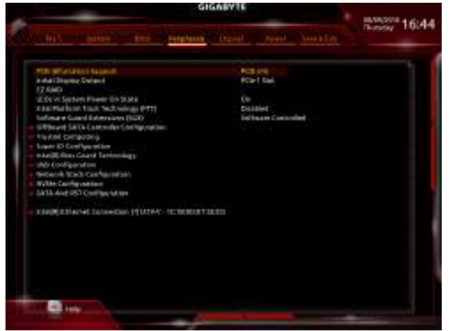
- Max Link Speed: Allows you to set the operation mode of the PCI Express slots to Gen 1, Gen 2, or Gen 3. Actual operation mode is subject to the hardware specification of each slot. Auto lets the BIOS automatically configure this setting. (Default: Auto)
- 3DMark01 Enhancement: Allows you to determine whether to enhance some legacy benchmark performance. (Default: Disabled)
Smart Fan 5 Settings
- Monitor: Allows you to select a target to monitor and to make further adjustment. (Default: CPU FAN)
- Fan Speed Control: Allows you to determine whether to enable the fan speed control function and adjust the fan speed.
- Normal: Allows the fan to run at different speeds according to the temperature. You can adjust the fan speed with System Information Viewer based on your system requirements. (Default)
- Silent: Allows the fan to run at slow speeds.
- Manual: Allows you to control the fan speed in the curve graph.
- Full Speed: Allows the fan to run at full speeds.
- Fan Control Use Temperature Input: Allows you to select the reference temperature for fan speed control.
- Temperature Interval: Allows you to select the temperature interval for fan speed change.
- Fan Control Mode:
- Auto: Lets the BIOS automatically detect the type of fan installed and sets the optimal control mode. (Default)
- Voltage: Voltage mode is recommended for a 3-pin fan.
- PWM: PWM mode is recommended for a 4-pin fan.
- Fan Stop: Enables or disables the fan stop function. You can set the temperature limit using the temperature curve. The fan stops operation when the temperature is lower than the limit. (Default: Disabled)
- Temperature: Displays the current temperature of the selected target area.
- Fan Speed: Displays current fan speeds.
- Temperature Warning Control: Sets the warning threshold for temperature. When temperature exceeds the threshold, BIOS will emit a warning sound. Options are: Disabled (default), 60°C/140°F, 70°C/158°F, 80°C/176°F, 90°C/194°F.
- Fan Fail Warning: Allows the system to emit a warning sound if the fan is not connected or fails. Check the fan condition or fan connection when this occurs. (Default: Disabled)
System
This section provides information on your motherboard model and BIOS version. You can also select the default language used by the BIOS and manually set the system time.
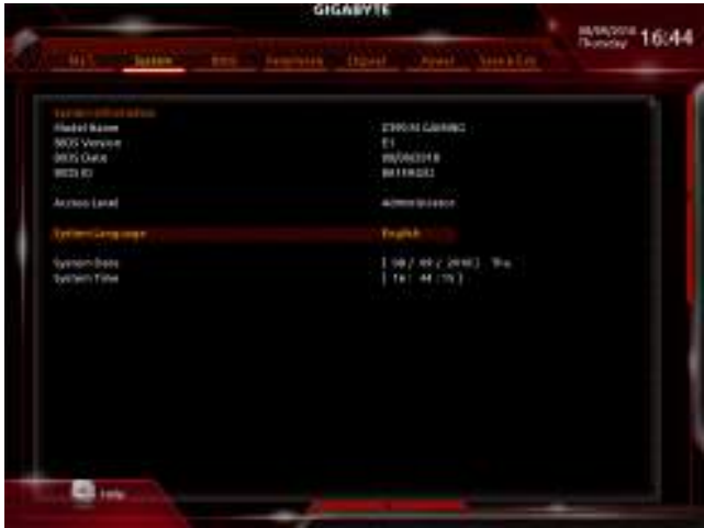
- Access Level: Displays the current access level depending on the type of password protection used. (If no password is set, the default will display as Administrator.) The Administrator level allows you to make changes to all BIOS settings; the User level only allows you to make changes to certain BIOS settings but not all.
- System Language: Selects the default language used by the BIOS.
- System Date: Sets the system date. The date format is week (read-only), month, date, and year. Use <Enter> to switch between the Month, Date, and Year fields and use the <Page Up> or <Page Down> key to set the desired value.
- System Time: Sets the system time. The time format is hour, minute, and second. For example, 1 p.m. is 13:00:00. Use <Enter> to switch between the Hour, Minute, and Second fields and use the <Page Up> or <Page Down> key to set the desired value.
BIOS
- Bootup NumLock State: Enables or disables the Numlock feature on the numeric keypad of the keyboard after the POST. (Default: On)
- Security Option: Specifies whether a password is required every time the system boots, or only when you enter BIOS Setup. After configuring this item, set the password(s) under the Administrator Password/User Password item.
- Setup: A password is only required for entering the BIOS Setup program.
- System: A password is required for booting the system and for entering the BIOS Setup program. (Default)
- Full Screen LOGO Show: Allows you to determine whether to display the GIGABYTE Logo at system startup. Disabled skips the GIGABYTE Logo when the system starts up. (Default: Enabled)
- Boot Option Priorities: Specifies the overall boot order from the available devices. Removable storage devices that support GPT format will be prefixed with the "UEFI:" string on the boot device list. To boot from an operating system that supports GPT partitioning, select the device prefixed with the "UEFI:" string. Or if you want to install an operating system that supports GPT partitioning such as Windows 10 64-bit, select the optical drive that contains the Windows 10 64-bit installation disk and is prefixed with the "UEFI:" string.
- Hard Drive/CD/DVD ROM Drive/Floppy Drive/Network Device BBS Priorities: Specifies the boot order for a specific device type, such as hard drives, optical drives, floppy disk drives, and devices that support Boot from LAN function, etc. Press <Enter> on this item to enter the submenu that presents the devices of the same type that are connected. This item is present only if at least one device for this type is installed.
- Fast Boot: Enables or disables Fast Boot to shorten the OS boot process. Ultra Fast provides the fastest bootup speed. (Default: Disabled)
SATA Support
- Last Boot HDD Only: Except for the previous boot drive, all SATA devices are disabled before the OS boot process completes. (Default)
- All Sata Devices: All SATA devices are functional in the operating system and during the POST. This item is configurable only when Fast Boot is set to Enabled or Ultra Fast.
- VGA Support: Allows you to select which type of operating system to boot.
- Auto: Enables legacy option ROM only.
- EFI Driver: Enables EFI option ROM. (Default) This item is configurable only when Fast Boot is set to Enabled or Ultra Fast.
- USB Support:
- Disabled: All USB devices are disabled before the OS boot process completes.
- Full Initial: All USB devices are functional in the operating system and during the POST. (Default)
- Partial Initial: Part of the USB devices are disabled before the OS boot process completes. This item is configurable only when Fast Boot is set to Enabled. This function is disabled when Fast Boot is set to Ultra Fast.
- PS2 Devices Support:
- Disabled: All PS/2 devices are disabled before the OS boot process completes.
- Enabled: All PS/2 devices are functional in the operating system and during the POST. (Default) This item is configurable only when Fast Boot is set to Enabled. This function is disabled when Fast Boot is set to Ultra Fast.
- Network Stack Driver Support:
- Disabled: Disables booting from the network. (Default)
- Enabled: Enables booting from the network. This item is configurable only when Fast Boot is set to Enabled or Ultra Fast.
- Next Boot After AC Power Loss:
- Normal Boot: Enables normal bootup upon the return of the AC power. (Default)
- Fast Boot: Keeps the Fast Boot settings upon the return of the AC power. This item is configurable only when Fast Boot is set to Enabled or Ultra Fast.
- Mouse Speed: Allows you to set the mouse cursor movement speed. (Default: 1X)
- Windows 8/10 Features: Allows you to select the operating system to be installed. (Default: Windows 8/10)
- CSM Support: Enables or disables UEFI CSM (Compatibility Support Module) to support a legacy PC boot process.
- Disabled: Disables UEFI CSM and supports UEFI BIOS boot process only.
- Enabled: Enables UEFI CSM. (Default)
- LAN PXE Boot Option ROM: Allows you to select whether to enable the legacy option ROM for the LAN controller. (Default: Disabled) This item is configurable only when CSM Support is set to Enabled.
- Storage Boot Option Control: Allows you to select whether to enable the UEFI or legacy option ROM for the storage device controller.
- Do not launch: Disables option ROM.
- UEFI: Enables UEFI option ROM only. (Default)
- Legacy: Enables legacy option ROM only. This item is configurable only when CSM Support is set to Enabled.
Other PCI devices
Allows you to select whether to enable the UEFI or Legacy option ROM for the PCI device controller other than the LAN, storage device, and graphics controllers.
- Do not launch: Disables option ROM.
- UEFI: Enables UEFI option ROM only. (Default)
- Legacy: Enables legacy option ROM only. This item is configurable only when CSM Support is set to Enabled.
Administrator Password
Allows you to configure an administrator password. Press <Enter> on this item, type the password, and then press <Enter>. You will be requested to confirm the password. Type the password again and press <Enter>. You must enter the administrator password (or user password) at system startup and when entering BIOS Setup. Differing from the user password, the administrator password allows you to make changes to all BIOS settings.
User Password
Allows you to configure a user password. Press <Enter> on this item, type the password, and then press <Enter>. You will be requested to confirm the password. Type the password again and press <Enter>. You must enter the administrator password (or user password) at system startup and when entering BIOS Setup. However, the user password only allows you to make changes to certain BIOS settings but not all. To cancel the password, press <Enter> on the password item and when requested for the password, enter the correct one first. When prompted for a new password, press <Enter> without entering any password. Press <Enter> again when prompted to confirm.
NOTE: Before setting the User Password, be sure to set the Administrator Password first.
Secure Boot
Allows you to enable or disable Secure Boot and configure related settings. This item is configurable only when CSM Support is set to Disabled.
Appendix
Configuring a RAID Set
RAID Levels
Before you begin, please prepare the following items:
- At least two SATA hard drives or SSDs. (Note 1) (To ensure optimal performance, it is recommended that you use two hard drives with identical model and capacity). (Note 2)
- Windows setup disk.
- Motherboard driver disk.
- A USB thumb drive.
Configuring the Onboard SATA Controller
A. Installing SATA hard drive(s) in your computer Install the hard drives/SSDs in the Intel® Chipset controlled connectors on the motherboard. Then connect the power connectors from your power supply to the hard drives.
B. Configuring SATA controller mode in BIOS Setup Make sure to configure the SATA controller mode correctly in system BIOS Setup. Steps:
- Go to Peripherals\SATA And RST Configuration, make sure SATA Controller(s) is enabled. To create RAID, set SATA Mode Selection to Intel RST Premium With Intel Optane System Acceleration. Then save the settings and restart your computer. Note: When using a PCIe SSD, make sure to set the Use RST Legacy OROM item under Peripherals\SATA And RST Configuration to Disabled. Then depending on the M.2 connector you use, set the corresponding PCIe Storage Dev on Port XX item to RST Controlled. Finally, save the settings and exit BIOS Setup.
- To use the EZ RAID feature, follow the steps in "C-1." To configure UEFI RAID, follow the steps in "C-2." To enter the legacy RAID ROM, refer to "C-3" for more information. Finally, save the settings and exit BIOS Setup.
The BIOS Setup menus described in this section may differ from the exact settings for your motherboard. The actual BIOS Setup menu options you will see shall depend on the motherboard you have and the BIOS version.
Using EZ RAID
GIGABYTE motherboards provide you with the EZ RAID feature, allowing you to quickly configure a RAID array with simplified steps. Steps:
- After restarting the computer, enter the BIOS Setup and go to Peripherals. Press <Enter> on the EZ RAID item. Select the type of hard drives you use for RAID in the Type tab and then press <Enter>.
- Go to the Mode tab to select a RAID level. RAID levels supported include RAID 0, RAID 1, RAID 10, and RAID 5 (the selections available depend on the number of hard drives being installed). Then press <Enter> to move to the Create tab. Click Proceed to begin.
- After completing, you'll be brought back to the Intel(R) Rapid Storage Technology screen. Under RAID Volumes, you can see the new RAID volume. To see more detailed information, press <Enter> on the volume to check for information on RAID level, stripe block size, array name, and array capacity, etc. (Note 1) An M.2 PCIe SSD cannot be used to set up a RAID set either with an M.2 SATA SSD or a SATA hard drive. (Note 2) Refer to "1-7 Internal Connectors," for the installation notices for the M.2 and SATA connectors.
UEFI RAID Configuration Steps:
- In BIOS Setup, go to BIOS and set CSM Support to Disabled. Save the changes and exit BIOS Setup.
- After the system reboot, enter BIOS Setup again. Then enter the Peripherals\Intel(R) Rapid Storage Technology sub-menu.
- On the Intel(R) Rapid Storage Technology menu, press <Enter> on Create RAID Volume to enter the Create RAID Volume screen. Enter a volume name with 1~16 letters (letters cannot be special characters) under the Name item and press <Enter>. Then, select a RAID level. RAID levels supported include RAID 0, RAID 1, RAID 10, and RAID 5 (the selections available depend on the number of hard drives being installed). Next, use the down arrow key to move to Select Disks.
- Under Select Disks item, select the hard drives to be included in the RAID array. Press the <Space> key on the hard drives to be selected (selected hard drives are marked with "X"). Then set the stripe block size. The stripe block size can be set from 4 KB to 128 KB. Once you have selected the stripe block size, set the volume capacity.
- After setting the capacity, move to Create Volume and press <Enter> to begin.
- After completing, you'll be brought back to the Intel(R) Rapid Storage Technology screen. Under RAID Volumes, you can see the new RAID volume. To see more detailed information, press <Enter> on the volume to check for information on RAID level, stripe block size, array name, and array capacity, etc.
Configuring Legacy RAID ROM
Enter the Intel legacy RAID BIOS setup utility to configure a RAID array. Skip this step and proceed with the installation of the Windows operating system for a non-RAID configuration. Steps:
- In BIOS Setup, go to BIOS and set CSM Support to Enabled and Storage Boot Option Control to Legacy. Next, go to Peripherals\SATA And RST Configuration and make sure Use RST Legacy OROM is set to Enabled. Save the changes and exit BIOS Setup. After the POST memory test begins and before the operating system boot begins, look for a message that says "Press <Ctrl-I> to enter Configuration Utility". Press <Ctrl> + <I> to enter the RAID Configuration Utility.
- After you press <Ctrl> + <I>, the MAIN MENU screen will appear. If you want to create a RAID array, select Create RAID Volume in MAIN MENU and press <Enter>.
- After entering the CREATE VOLUME MENU screen, enter a volume name with 1~16 letters (letters cannot be special characters) under the Name item and press <Enter>. Then, select a RAID level. RAID levels supported include RAID 0, RAID 1, RAID 10, and RAID 5 (the selections available depend on the number of hard drives being installed). Press <Enter> to proceed.
- Under Disks item, select the hard drives to be included in the RAID array. If only two hard drives are installed, they will be automatically assigned to the array. Set the stripe block size if necessary. The stripe block size can be set from 4 KB to 128 KB. Once you have selected the stripe block size, press <Enter>.
- Enter the array capacity and press <Enter>. Finally press <Enter> on the Create Volume item to begin creating the RAID array. When prompted to confirm whether to create this volume, press <Y> to confirm or <N> to cancel.
- When completed, you can see detailed information about the RAID array in the DISK/VOLUME INFORMATION section, including the RAID level, stripe block size, array name, and array capacity, etc. To exit the RAID BIOS utility, press <Esc> or select 6. Exit in MAIN MENU.
Install the SATA RAID/AHCI driver and operating system
With the correct BIOS settings, you are ready to install the operating system.
Installing the Operating System
As some operating systems already include Intel® RAID/AHCI driver, you do not need to install separate RAID/AHCI driver during the Windows installation process. After the operating system is installed, we recommend that you install all required drivers from the motherboard driver disk using "Xpress Install" to ensure system performance and compatibility. If the operating system to be installed requires that you provide additional SATA RAID/AHCI driver during the OS installation process, please refer to the steps below:
- Copy the IRST folder under \Boot in the driver disk to your USB thumb drive.
- Boot from the Windows setup disk and perform standard OS installation steps. When the screen requesting you to load the driver appears, select Browse.
- Then browse to the USB flash drive and select the location of the driver. The location of the driver is as follows: \IRST\f6flpy-x64
- When a screen as shown, select Intel Chipset SATA RAID Controller and click Next to load the driver and continue the OS installation.
Troubleshooting
If you encounter any issues with the Gigabyte Motherboard Gaming Z390, here are some common problems and solutions:
- If your system won't boot, make sure that all cables are properly connected and that the power supply is turned on.
- If you're experiencing memory issues, try reseating the memory modules and making sure they are properly aligned.
- If your system is overheating, use the Smart Fan 5 technology to adjust the fan speeds and keep the system cool.
- If you're experiencing connectivity issues, make sure that the Wi-Fi module is properly installed and that the drivers are up to date.
Gigabyte Motherboard Gaming Z390 Pros & Cons
Pros
- High-performance motherboard with Intel Z390 chipset
- Sleek design with RGB Fusion technology
- Onboard Wi-Fi and high-speed USB 3.1 Gen 2 ports
- Smart Fan 5 technology for cooling
- Compatible with 8th and 9th generation Intel Core processors
Cons
- May be expensive for some users
- No built-in USB-C front panel connector
- No integrated IO shield
Faqs
Which processors are compatible with the Gigabyte Motherboard Gaming Z390?
Is NVMe SSD support available for the Gigabyte Gaming motherboard?
How many PCIe slots does the motherboard of the Gigabyte have available?
What audio codec does the motherboard of the Gigabyte Gaming use?
Which connectivity choices does the motherboard of the Gigabyte Motherboard Gaming Z390 offer?
Is there built-in WiFi on the motherboard?
When was the Gigabyte launched?
BIOS features come with the motherboard Gigabyte?
What is the estimated price of the Gigabyte?
How long is the Gigabyte Motherboard Gaming Z390 warranty valid?
Leave a Comment