Impex Marcy Diamond Smith Machine MD-9010 User Guide
Content
Introduction
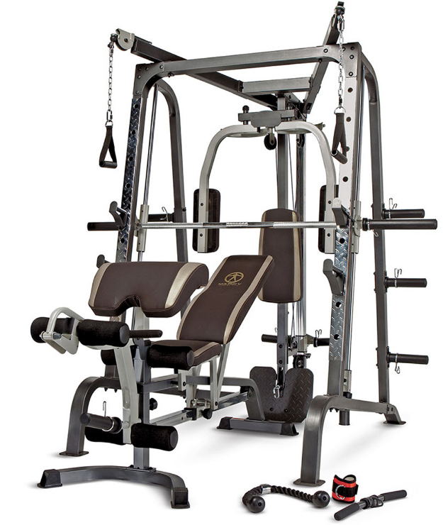
The Impex Marcy Diamond Smith Machine MD-9010 is a comprehensive home gym system designed for serious strength training. This versatile machine combines a Smith bar, free weight squat rack, and cable pulleys, allowing users to perform over 100 exercises. Its heavy-duty steel construction ensures durability, while the adjustable bench and various attachments enhance workout flexibility. Priced at approximately $600, the MD-9010 offers an all-in-one solution for fitness enthusiasts looking to maximize their home gym experience.
Detailed Specifications
The Impex Marcy Diamond Smith Machine MD-9010 boasts several key features that make it a standout in the market:
- Heavy-Duty Steel Frame: Constructed from high-quality steel for maximum durability.
- Adjustable Safety Stops: Ensures safe lifting by allowing users to set the bar at desired heights.
- Multi-Grip Bar: Offers various grip positions for different exercises.
- Smooth-Gliding Rails: Provides a smooth and stable bar movement.
- Compact Design: Ideal for home gyms with limited space.
- Weight Capacity: Supports up to 300 lbs (136 kg) of weight.
SMITH MACHINE HARDWARE PACK
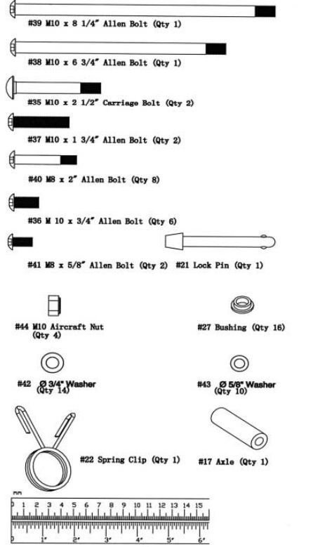
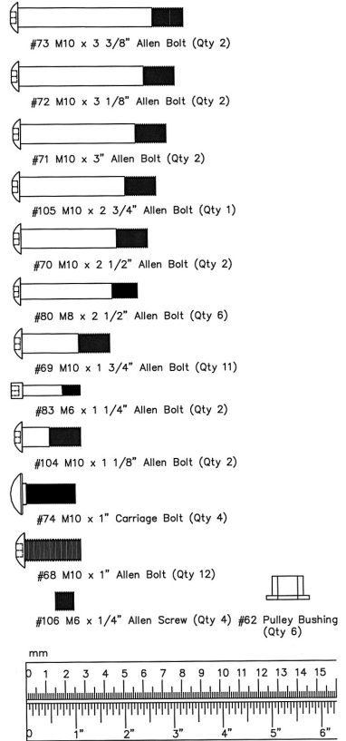
Description
The Impex Marcy Diamond Smith Machine MD-9010 is engineered to deliver a comprehensive workout experience. Its compact design makes it perfect for home gyms, while its robust construction and smooth-gliding rails ensure a professional-grade workout. The adjustable safety stops provide peace of mind during heavy lifts, and the multi-grip bar offers flexibility in exercise selection. This machine is ideal for those looking to invest in a reliable piece of equipment that can support a wide range of strength training exercises.
ASSEMBLY INSTRUCTION
Tools Required Assembling the Machine: Two Adjustable Wrenches and Allen Wrenches.
NOTE: It is strongly recommended two or more people assembling this machine to avoid possible injury.
STEP 1 (See Diagram 1)
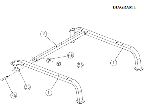
- A.) Connect the two Base Frames (#1) by a Cross Brace (#2) in the mid-span. Secure each end of The Cross Brace with two M10 x 3 ½” Carriage Bolts (#79), one 4 ¾” x 2” Bracket (#36), two Ø ¾” Washers (#66), and two M10 Aircraft Nuts (#86).
- B.) NOTE: DO NOT tighten the Nuts and Bolts yet.
STEP 2 (See Diagram 2)
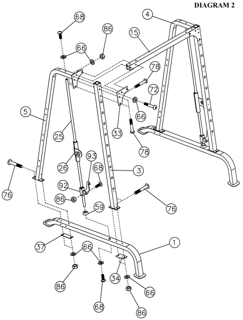
- Attach a Front Vertical Frame (#3) to the right Base Frame (#1). Secure it with two M10 x 3” Carriage Bolts (#76), one 5 1/8” x 2 ¾” Bracket (#34), two Ø ¾” Washers (#66), and two M10 Aircraft Nuts (#86). Do not tighten the Nuts and Bolts yet.
- Align a Ø 2 ½” Rubber Bumper (#59) to the hole on the Base Frame. Insert a Guide Rod (#25) through the Rubber Bumper and into the Base Frame. Secure it with one M10 x 1” Allen Bolt (#68) and Ø ¾” Washer (#66).
- Slide a Lower Safety Stop Frame (#92) onto the Guide Rod (#25). Secure the Safety Hook (#93) to the Lower Safety Stop Frame (#92) with a M10 x 1” Allen Bolt (#68) and M10 Aircraft Nut (#86). Attach the Hook onto the back of the Front Vertical Beam (#3).
- Slide a Safety Stop Frame (#26) onto the Guide Rod (#25).
- Attach the hole on top of the Right Vertical Frame (#5) to the top of the Guide Rod (#25). Attach the top of Right Vertical Frame (#5) to the top of Front Vertical Frame (#3). Attach the bottom of Right Vertical Frame (#5) to the Base Frame (#1).
- Secure the Guide Rod (#25) to the Right Vertical Frame (#5) with one M10 x 1” Allen Bolt (#68) and Ø ¾” Washer (#66).
- Secure the Right Vertical Frame (#5) to the Base Frame with two M10 x 3” Carriage Bolts
- (#76), one 6 ¼” x 2” Bracket (#37), two Ø ¾” Washers (#66), and two M10 Aircraft Nuts
- (#86). Do not tighten the Nuts and Bolts yet.
- Secure the Right Vertical Frame (#5) to the Front Vertical Beam (#3) with one Triangle Bracket (#33), M10 x 3 1/8” Allen Bolt (#72), and ∅ ¾” Washer (#66) to the top hole. Secure the bottom two holes with two M10 x 3 3/8” Carriage Bolts (#78), ∅ ¾” Washers (#66) and M10 Aircraft Nuts (#86).
- Repeat the above Procedures A through H to install the other side.
- Attach the Front Top Beam (#15) to the Front Vertical Beams (#3) and the Triangle Brackets (#33). Align the Holes. Secure each end with two M10 x 3 3/8” Carriage Bolts (#78), Ø ¾” Washers (#66), and M10 Aircraft Nuts (#86).
- Do NOT tighten all the Nuts and Bolts yet.
STEP 3 (See Diagram 3)

- Attach the Rear Vertical Beam (#6) to the top of the Cross Brace (#2). Attach the Weight Glide Base (#8) to the Cross Brace from the Bottom. Align the holes. Secure them with two M10 x 3” Carriage Bolts (#76), Ø ¾” Washers (#66), and M10 Aircraft Nuts (#86).
- Attach the Pulley Support Frame (#97) to the Rear Vertical Beam. Secure it with two M10 x 2 ¾” Carriage Bolts (#75), one 4 ¾” x 2” Bracket (#36), two Ø ¾” Washers (#66), and two M10 Aircraft Nuts (#86).
- Attach the Backrest Board (#38) to the Rear Vertical Beam. Secure it with two M8 x 2 ½” Allen Bolts (#80) and Ø 5/8” Washers (#65).
STEP 4 (See Diagram 4)
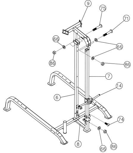
- Attach the Weight Glide Post (#7) onto the Weight Glide Base (#8). Secure it with four M10 x 1” Carriage Bolts (#74), Ø ¾” Washers (#66) and M10 Aircraft Nuts (#86).
- Slide the Sliding Weight Post (#14) onto the Chromed Post from the top. Place the Rear Upper Frame (#9) onto the Weight Glide Post (#7) and Rear Vertical Beam (#6).
- Align the holes. Secure the Rear Upper Frame to the Weight Glide Post with two M10 x 3” Allen Bolts (#71), four Ø ¾” Washers (#66), and two M10 Aircraft Nuts (#86). Do not tighten the Nuts and Bolts yet.
- Secure the Upper Frame to the Rear Vertical Beam (#6) with two M10 x 2 ¾” Carriage Bolts (#75), ∅ ¾” Washers (#66) and M10 Aircraft Nuts (#86).
STEP 5 (See Diagram 5)
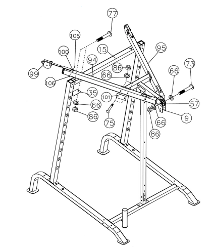
- Place the Left Upper Frame (#94) onto the Front Top Beam (#15). Secure it with two M10 x 3 1/8” Carriage Bolts (#77), one 5 1/8” x 2 3/8” Bracket (#35), two Ø ¾” Washers (#66), and two M10 Aircraft Nuts (#86).
- Secure the Left Upper Frame (#94) to the Rear Upper Frame with two M10 x 2 ¾” Carriage Bolts (#75), one 4 ¾” x 2 ¾” Bracket (#101), two Ø ¾” Washers (#66), and M10 Aircraft Nuts (#86).
- Insert a Cross-Over Swivel Pulley Bracket (#99) into the sleeve on the Left Upper Frame. Secure it with one Ø 7/8” x 5/8” Bushing and two M6 x ¼” Allen Screws (#106).
- Repeat procedures A, B and C above to install the Right Upper Frame (#95). Place a Pulley (#57) in the opening on the Rear Upper Frame (#9). Secure the Pulley, the rear of Left & Right Upper Frames (#94 & 95), and the Rear Upper Frame (#9) all together with one M10 x 3 3/8” Allen Bolt (#73), two Ø ¾” Washers (#66), and one M10 Aircraft Nut (#86).
STEP 6 (See Diagram 6)
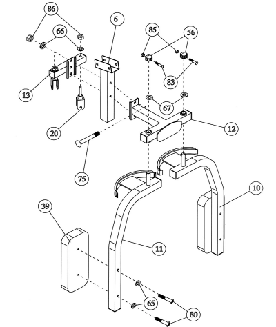
- Securely tighten all Nuts and Bolts previously installed.
- Attach the Butterfly Base (#12) to the front of Rear Vertical Beam (#6). Attach the Butterfly Pulley Bracket (#13) to the back of the Rear Vertical Beam. Align the holes. Secure them with two M10 x 2 ¾” Carriage Bolts (#75), Ø ¾” Washers (#66), and M10 Aircraft Nuts (#86).
- Attach the Right Butterfly (#11) to the hole on the Butterfly Base. Secure it with one Lock Ring (#56), Ø 1 ½” Washer (#67), M6 x 1 ¼” Allen Bolt (#83), and M6 Aircraft Nut (#85).
- Attach the Butterfly Arm Pad (#39) to the Right Butterfly. Secure it with two M8 x 2 ½” Allen Bolts (#80) and Ø 5/8” Washers (#65).
- Repeat Procedures C and D above to install the other side.
- Insert two Swivel Pulley Brackets (#20) into the holes on the Butterfly Pulley Bracket (#13). Secure each Swivel Pulley Bracket with one Ø ¾” Washer (#66) and M10 Aircraft Nut (#86). Do not over tighten the Nuts. Make sure the Brackets are able to swivel.
CABLE LOOP DIAGRAM
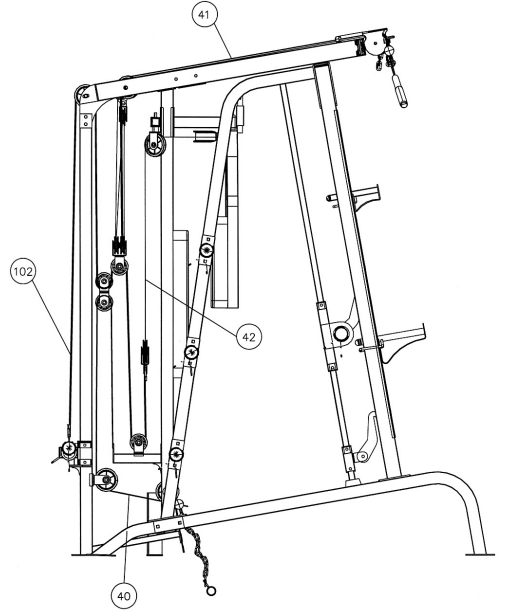
STEP 7 (See Diagram 7 & Cable Loop Diagram)
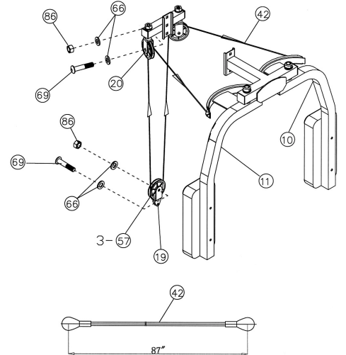
- Attach one end of 87” Butterfly Cable (#42) to the clip on Right Butterfly (#11). Draw the Cable to the right Swivel Pulley Bracket (#20).
- Attach a Pulley (#57) to the Bracket. Secure it with one M10 x 1 ¾” Allen Bolt (#69), two Ø ¾” Washers (#66), and one M10 Aircraft Nut (#86).
- Draw the Cable around the Pulley then downward. Attach a Single Floating Pulley Bracket (#19) to the Cable. Repeat Procedure B above to install a Pulley. Let the Bracket hanging for now. D.) Draw the Cable around the Pulley then upward to the left Swivel Pulley Bracket. Repeat Procedure B above to install a Pulley to the Bracket.
- Draw the Cable around the Pulley then clip to the Left Butterfly (#10).
STEP 8 (See Diagram 8 & Cable Loop Diagram)
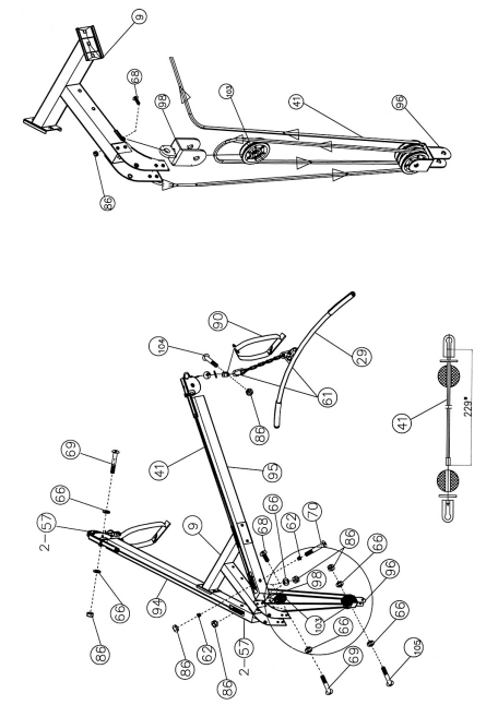
- Un-install the M10 x 1 1/8” Allen Bolt (#104) and M10 Aircraft Nut (#86) on the U-shaped Connector on one end of the 229” Cable (41). Remove the U-shaped Connector, Big Washer, and Ball Stopper from the Cable.
- Insert the end of Cable through the left Cross-over Swivel Pulley Bracket (#99). Attach a Pulley (#57) to the Swivel Bracket and secure it with one M10 x 1 ¾” Allen Bolt (#69), two Ø ¾” Washers (#66), and one M10 Aircraft Nut (#86). Draw the Cable over the Pulley and pull it towards the back of the machine.
- Draw the Cable along the Left Upper Frame (#94) to the opening on the rear of the Frame. Drop the cable through the opening.
- Attach a Pulley to the opening. Secure it with one M10 x 2 ½” Allen Bolt (#70), two Pulley Bushings (#62), and one M10 Aircraft Nut (#86). Draw the Cable around the Pulley then downward.
- Attach two Small Pulleys (#103) to the Triple Floating Pulley Bracket (#96). Secure them to the Bracket with one M10 x 2 ¾” Allen Bolt (#105), two Ø ¾” Washers (#66), and one M10 Aircraft Nut (#86).
- Draw the Cable around the back Pulley then upward to the bracket underneath the Rear Upper Frame (#9). Install a Single Small Pulley Bracket (#98) to the bottom of Rear Upper Frame (#9). Secure it with one M10 x 1” Allen Bolt (#68), two Ø ¾” Washers (#66), and one M10 Aircraft Nut (#86). Install a Small Pulley to the Single Small Pulley Bracket.
- Draw the Cable around the Small Pulley then downward to the Triple Floating Pulley Bracket. Draw the Cable around the front Small Pulley then upward to the opening on the rear of Right Upper Frame (#95). Let the Triple Floating Pulley Bracket hanging for now. H.) Install a Pulley to the opening. Draw the Cable over the Pulley along the top of the Right Upper Frame through the cable sleeve to the right Cross-over Swivel Pulley Bracket. Install a Pulley to the Bracket.
- Re-install the Ball Stopper, Big Washer and the U-shaped Connector previously removed in Procedure A above. Secure it with the M10 x 1 1/8” Allen Bolt (#104) and M10 Aircraft Nut (#86).
- Connect a Single Handle Strap (#90) to each end of the Cable with a C-clip (#61).
- When using the Lat Bar, remove one of the Strap and connect the Lat Bar to end of the Cable with a Short Chain (#63) and two C-clips (#61).
STEP 9 (See Diagram 9 & Cable Loop Diagram)
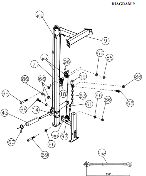
- Attach one end of the 138” Sliding Weight Post Cable (#102) to the open bracket on the Sliding Weight Post (#14). Secure it with one M10 x 1” Allen Bolt (#68), two Ø ¾” Washers (#66), and one M10 Aircraft Nut (#86).
- Draw the Cable upward to the Pulley on the top of the Rear Upper Frame (#9) previously installed in Step-5.
- Draw the Cable around the Pulley then downward. Install a Small Pulley (#103) to a Double Floating Pulley Bracket (#18).
- Draw the Cable around the Pulley then to the Triple Floating Pulley Bracket (#96) previously installed in Step-8.
- Install a Small Pulley to the Bracket. Draw the Cable around the Small Pulley then downward to the open bracket on the Pulley Support Frame (#97).
- Install a Small Pulley to the bracket. Draw the Cable around the Small Pulley then upward. G.) Connect the Cable to a Short Chain (#63) with a C-clip (#61). Connect the Short Chain to the Single Floating Pulley Bracket (#19) previously installed in Step-7. Secure the Chain with one M10 x 1” Allen Bolt (#68), two Ø ¾” Washers (#66), and one M10 Aircraft Nut (#86).
- After completing the entire cable installations, come back to this Short Chain to adjust the tension of the Cable system by adjusting the length of the Chain.
- Install two Olympic Sleeves (#43) and Spring Clips (#60) onto the Sliding Weight Post (#14).
STEP 10 (See Diagram 10)
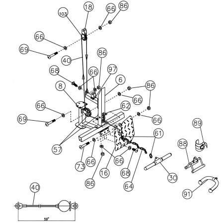
- Attach the 59” Lower Cable (#40) to a Pulley (#57). Attach the Pulley to the lower opening on the Rear Vertical Beam (#6). Secure it with the Foot Plate (#16), one M10 x 3 3/8” Allen Bolt (#73), two Ø ¾” Washers (#66), and one M10 Aircraft Nut (#86). Secure the Foot Plate to the Cross Brace (#2) with two M10 x1” Allen Bolts (#68), four Ø ¾” Washers (#66) and two M10 Aircraft Nuts (#86).
- Draw the Cable underneath the Pulley to the open bracket on the Weight Glide Base (#8).
- Install a Pulley to the bracket. Draw the Cable around the Pulley then upward to the Double Floating Pulley Bracket (#18) previously installed in Step-9.
- Install a Small Pulley (#103) to the Bracket. Draw the Cable around the Pulley then downward to the open bracket on the Pulley Support Frame (#97). Secure the end of the Cable to the bracket with one M10 x 1” Allen Bolt (#68), two Ø ¾” Washers (#66) and one M10 Aircraft Nut (#86).
- Connect the Shiver Bar (#30) to a Long Chain (#64) with a C-clip (#61). Connect the long Chain to the Cable with another C-clip.
STEP 11 (See Diagram 11)
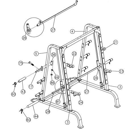
- NOTE: The help of another person is strongly recommended for this step. Place the Lifting Sleeve (#27) in between the two Safety Stop Frames (#26). Align the holes. Insert the Weight Bar (#28) into the Safety Stop Frame from one end and through the Lifting Sleeve (#27) to the other Safety Stop Frame on the opposite side. Secure the Weight Bar to each Safety Stop Frame with a M8 x 3/8” Allen Bolt (#81).
- Turn the safety catch hook forward on the Lifting Sleeve to secure its position on the selected holes on the Front Vertical Frames (#3). Attach a Long Olympic Sleeve (#44) to each end of the Weight Bar. Attach a Spring Clip (#60) to the Sleeve.
- Attach six Weight Posts (#17) to the Left & Right Vertical Frames (#4&5). Secure each Weight Post with two M10 x 2 ¾” Carriage Bolts (#75), one 4 ¾” x 2” Bracket (#36), two Ø ¾” Washers (#66), and two M10 Aircraft Nuts (#86).
- Attach six Olympic Sleeves (#43) to the Weight Posts. Attach Spring Clips (#60) to the sleeves. Insert the Left & Right Bar Holders (#21 & 22), the Left & Right Safety Catches (#23 & 24) into the selected holes on the Front Vertical Frames (#3).
EXPLODED DIAGRAM
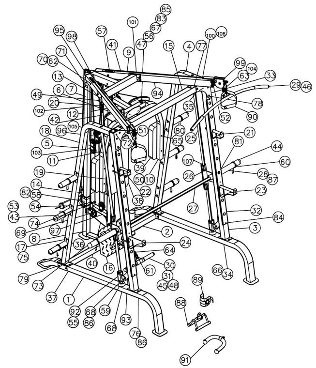
PARTS LIST
| 1 Base Frame | 2 | 55 | Sliding Sleeve 4 | |
| 2 Cross Brace | 1 | 56 | Lock Ring 2 | |
| 3 Front Vertical Beam | 2 | 57 | Pulley 10 | |
| 4 Left Vertical Frame | 1 | 58 | Ø 1 ¾” RubberBumper 1 | |
| 5 Right Vertical Frame | 1 | 59 | Ø 2 ½” RubberBumper 2 | |
| 6 Rear Vertical Beam | 1 | 60 | Spring Clip 10 | |
| 7 Weight Glide Post | 1 | 61 | C-clip | 5 |
| 8 Weight Glide Base | 1 | 62 | Pulley Bushing | 6 |
| 9 Rear Upper Frame | 1 | 63 | Short Chain | 2 |
| 10 Left Butterfly | 1 | 64 | Long Chain | 1 |
| 11 Right Butterfly | 1 | 65 | Ø 5/8” Washer | 6 |
| 12 Butterfly Base | 1 | 66 | Ø ¾” Washer | 100 |
| 13 Butterfly Pulley Bracket | 1 | 67 | Ø 1 ½” Washer | 2 |
| 14 Sliding Weight Post | 1 | 68 | M10 x 1” Allen Bolt | 12 |
| 15 Front Top Beam | 1 | 69 | M10 x 1 ¾” Allen Bolt | 11 |
| 16 Foot Plate | 1 | 70 | M10 x 2 ½” Allen Bolt | 2 |
| 17 Weight Post | 6 | 71 | M10 x 3” Allen Bolt | 2 |
| 18 Double Floating Pulley Bracket | 1 | 72 | M10 x 3 1/8” Allen Bolt | 2 |
| 19 Single Floating Pulley Bracket | 1 | 73 | M10 x 3 3/8” Allen Bolt | 2 |
| 20 Swivel Pulley Bracket | 2 | 74 | M10 x 1” Carriage Bolt | 4 |
| 21 Left Bar Holder | 1 | 75 | M10 x 2 ¾” Carriage Bolt | 22 |
| 22 Right Bar Holder | 1 | 76 | M10 x 3” Carriage Bolt | 10 |
| 23 Left Safety Catch | 1 | 77 | M10 x 3 1/8” Carriage Bolt | 4 |
| 24 Right Safety Catch | 1 | 78 | M10 x 3 3/8” Carriage Bolt | 8 |
| 25 Guide Rod | 2 | 79 | M10 x 3 ½” Carriage Bolt | 4 |
| 26 Safety Stop Frame | 2 | 80 | M8 x 2 ½” Allen Bolt | 6 |
| 27 Lifting Sleeve | 1 | 81 | M8 x 3/8” Allen Bolt | 8 |
| 28 Weight Bar | 1 | 82 | M6 x 5/8” Philips Screw | 1 |
| 29 Lat Bar | 1 | 83 | M6 x 1 ¼” Allen Bolt | 2 |
| 30 Shiver Bar | 1 | 84 | Chrome Panel Screw | 8 |
| 31 Curl Handle | 1 | 85 | M6 Aircraft Nut | 2 |
| 32 Chrome Panel | 2 | 86 | M10 Aircraft Nut | 82 |
| 33 Triangle Bracket | 2 | 87 | Ø 1” End Cap | 6 |
| 34 5 1/8” x 2 ¾” Bracket | 2 | 88 | V Bar | 1 |
| 35 5 1/8” x 2 3/8” Bracket | 2 | 89 | Ankle Strap | 1 |
| 36 4 ¾” x 2” Bracket | 9 | 90 | Single Handle Strap | 2 |
| 37 6 ¼” x 2” Bracket | 2 | 91 | Triceps Rope | 1 |
| 38 Backrest Board | 1 | 92 | Lower Safety Stop Frame | 2 |
| 39 Butterfly Arm Pad | 2 | 93 | Safety Hook | 2 |
| 40 59” Lower Cable | 1 | 94 | Left Upper Frame | 1 |
| 41 229” Upper Cable | 1 | 95 | Right Upper Frame | 1 |
| 42 87” Butterfly Cable | 1 | 96 | Triple Floating Pulley Bracket | 1 |
| 43 Olympic Sleeve | 8 | 97 | Pulley Support Frame | 1 |
| 44 Long Olympic Sleeve | 2 | 98 | Single Small Pulley Bracket | 1 |
| 45 Curl Bar Handle Grip | 2 | 99 | Cross-Over Swivel Pulley Bracket | 2 |
| 46 Lat Bar Grip | 2 | 100 | Ø 7/8” x Ø 5/8” Bushing | 2 |
| 47 Ø 1” x 3 1/8” Bushing | 2 | 101 | 4 ¾” x 2 ¾” Bracket | 2 |
| 48 Ø 1 ½” x 1” Bushing | 2 | 102 | 138” Sliding Weight Post Cable | 1 |
| 49 1 ½” Square End Cap | 2 | 103 | Small Pulley | 7 |
| 50 1 ¾” Square End Cap | 7 | 104 | M10 x 1 1/8” Allen Bolt | 2 |
51 2 3/8” Square End Cap | 2 | 105 | M10 x 2 ¾” Allen Bolt | 1 |
52 2 ¾” x 2” End Cap | 2 | 106 | M6 x ¼” Allen Screw | 4 |
53 Ø 1” Cone-shaped End Cap | 12 | 107 | Linear Bearing | 4 |
54 2 3/8” x 2” Sleeve | 2 |
|
|
|
MULTI-PURPOSE BENCH HARDWARE PACK

BENCH ASSEMBLY INSTRUCTION
Tools Required Assembling the Machine: Two Adjustable Wrenches and Allen Wrenches.
NOTE: It is strongly recommended this machine be assembled by two or more people to avoid possible injury.
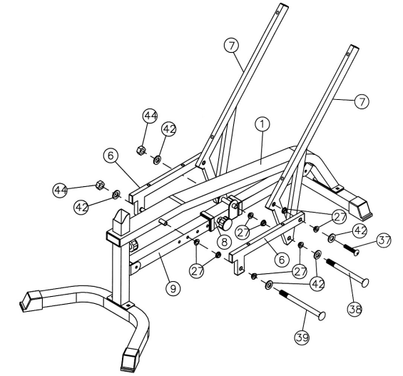
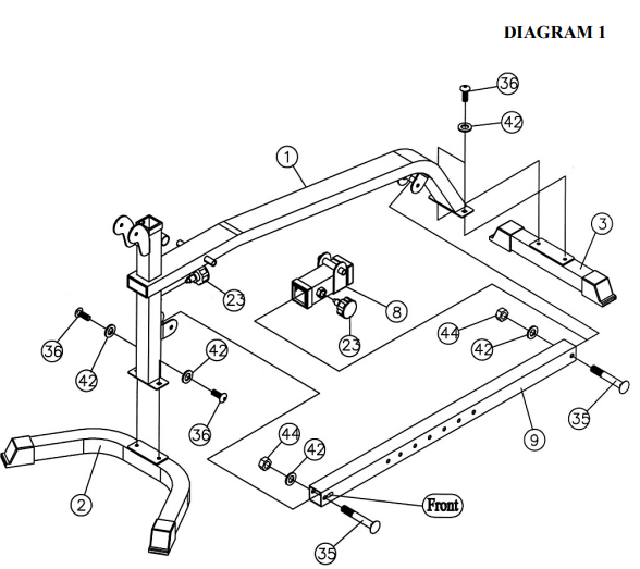
STEP 1 (See Diagram 1)

- A.) Attach the Main Frame (#1) to the Front & Rear Stabilizers (#2 & 3). Secure each end with two M10 x ¾” Allen Bolts (#36) and ∅ ¾” Washers (#42). Attach a Lock Knob (#23) to the hole underneath the Main Frame.
- B.) Slide the Sliding Block (#8) onto the Incline Adjustment Bar (#9). Align the hole then secure it with a Lock Knob (#23) to hold the Sliding Block in position.
- C.) Attach the Incline Adjustment Bar to the brackets on the Main Frame. Secure each end with
STEP 2 (See Diagram 2)

- A.) Attach four Bushings (#27) to a Seat Support Frame (#6).
- B.) Attach a Backrest Support (#7) to the rear of the Seat Support Frame (#6). Align the holes and secure them with one M10 x 1 ¾” Allen Bolt (#37) and ∅ ¾” Washer (#42). Repeat the same procedure to install the other side.
- C.) Attach two Bushings to the pivot on the Sliding Block (#8). Attach two Bushings to each Backrest Supports (#7). Align the holes and secure them with one M10 x 6 ¾” Allen Bolt (#38), two ∅ ¾” Washers (#42), and one M10 Aircraft Nut (#44). Do not over tighten the nut and bolt. The Supports need to swivel on the Bolt.
- D.) Attach two Bushings to the pivot on the Main Frame (#1). Loosen and pull the Lock Knob on the Sliding Block (#8). The Sliding Block needs to be able to slide on the Chromed Incline Adjustment Bar (#9). Align the two Seat Support Frames (#6) to both ends of the pivot on Main Frame. Secure them with one M10 x 8 ¼” Allen Bolt (#39), two ∅ ¾” Washers (#42), and one M10 Aircraft Nut (#44). Use the Lock Knob on the Sliding Block (#8) to adjust and secure the backrest incline position.
STEP 3 (See Diagram 3)

- A.) Place the Backrest Board (#14) onto the Backrest Supports (#7). Secure it with four M8 x 2” Allen Bolts (#40) and ∅ 5/8” Washers (#43).
- B.) Place the Seat Pad (#13) onto the Seat Support Frames (#6). Secure it with four M8 x 2” Allen Bolts (#40) and ∅ 5/8” Washers (#43).
STEP 4 (See Diagram 4)

- A.) Attach the Leg Developer (#5) to the open bracket on the Main Frame (#1). Secure it with an Axle (#17), two M10 x ¾” Allen Bolts (#36), and two ∅ ¾” Washers (#42).
- B.) Insert one Foam Tube (#10) halfway through the hole on the Main Frame. Insert two Foam Tubes halfway through the holes on the Leg Developer (#5). Push six Foam Rolls (#24) onto the Tubes from both ends. Plug six Foam Roll End Caps (#25) into the Tubes.
- C.) Slide the Olympic Sleeve (#20) onto the weight post on the Leg Developer. Attach a Spring Clip (#22) to the Sleeve.
STEP 5 (See Diagram 5)

- A.) Attach the Arm Curl Pad (#15) to the Arm Curl Stand (#4). Secure it with two M8 x 5/8” Allen Bolts (#41) and two ∅ 5/8” Washers (#43). Insert the Arm Curl Stand into the front opening on the Main Frame (#1). Use the Lock Knob to hold the desired Arm Curl height.
- B.) Attach the Arm Curl Handle (#11) to the open bracket on the Leg Developer (#5). Lock it with a Lock Pin (#21).
- C.) Remove the Pin and Arm Curl Handle when using the Leg Developer to exercise.
Bench Exploded Diagram
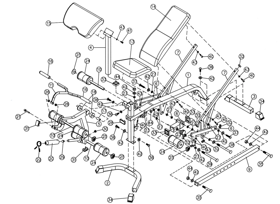
MULTI-PURPOSE BENCH PARTS LIST
KEY NO. | DESCRIPTION | Q’ty |
1 | Main Frame | 1 |
2 | Front Stabilizer | 1 |
3 | Rear Stabilizer | 1 |
4 | Arm Curl Stand | 1 |
5 | Leg Developer | 1 |
6 | Seat Support Frame | 2 |
| 7 | Backrest Support | 2 |
| 8 | Sliding Block | 1 |
| 9 | Incline Adjustment Bar | 1 |
| 10 | Foam Tube | 3 |
| 11 | Arm Curl Handle | 1 |
| 12 | Manual | 1 |
| 13 | Seat Pad | 1 |
| 14 | Backrest Board | 1 |
| 15 | Arm Curl Pad | 1 |
| 16 | Curl Bar Handle Grip | 2 |
| 17 | Axle | 1 |
| 18 | Ø 2 3/8” Bushing | 2 |
| 19 | Tool | 2 |
| 20 | Olympic Sleeve | 1 |
| 21 | Lock Pin | 1 |
| 22 | Spring Clip | 1 |
| 23 | Lock Knob | 2 |
| 24 | Foam Roll | 6 |
| 25 | Foam Roll End Cap | 6 |
| 26 | Ø 1” x ¾” Bushing | 2 |
| 27 | Bushing | 16 |
| 28 | 3 1/8” x 1 5/8” End Cap | 1 |
| 29 | Ø 1” Cone-shaped End Cap | 1 |
| 30 | Ø 1” End Cap | 1 |
| 31 | 1 5/8” x 2 3/8” End Cap | 2 |
| 32 | 1 5/8” x ¾” End Cap | 12 |
| 33 | 2” Sliding Block Sleeve | 3 |
| 34 | Stabilizer End Cap | 4 |
| 35 | M10 x 2 ½” Carriage Bolt | 2 |
| 36 | M10 x ¾” Allen Bolt | 6 |
| 37 | M10 x 1 ¾” Allen Bolt | 2 |
| 38 | M10 x 6 ¾” Allen Bolt | 1 |
| 39 | M10 x 8 ¼” Allen Bolt | 1 |
| 40 | M8 x 2” Allen Bolt | 8 |
| 41 | M8 x 5/8” Allen Bolt | 2 |
| 42 | Ø ¾” Washer | 14 |
| 43 | Ø 5/8” Washer | 10 |
| 44 | M10 Aircraft Nut | 4 |
MD-9010 WEIGHT RESISTANCE CHART
Station | Ratio | Example |
Low Pulley | 200% | 10 lb. plate creates 20 lb. resistance |
Lat Pull | 100% | 10 lb. plate creates 5 lb. resistance |
Butterfly (both arms) | 100% | 10 lb. plate creates 10 lb. resistance |
Left Cross-Over | 50% | 10 lb. plate creates 5 lb resistance |
Right Cross-Over | 50% | 10 lb. plate creates 5 lb resistance |
*Numbers are approximate. Actual resistance may vary.
Setup Guide
Setting up the Impex Marcy Diamond Smith Machine MD-9010 is relatively straightforward but requires careful attention to detail:
- Unpack and Organize Parts: Carefully unpack all components and organize them according to the instruction manual.
- Assemble Frame: Follow the instructions to assemble the frame, ensuring all bolts and screws are securely tightened.
- Attach Rails and Safety Stops: Install the gliding rails and adjust the safety stops according to your preferred lifting heights.
- Final Check: Double-check all connections and ensure the machine is stable before use.
Troubleshooting
Common problems with the Impex Marcy Diamond Smith Machine MD-9010 can often be resolved with simple troubleshooting steps:
- Bar Stuck or Jerky Movement: Check if the rails are properly aligned and clean. Apply lubricant if necessary.
- Safety Stops Not Adjusting: Ensure all bolts are loose before adjusting; then tighten securely.
- Frame Instability: Verify that all bolts and screws are tightened properly during assembly.
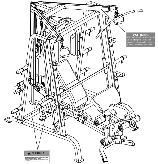
Warning: Always follow the manufacturer's instructions for assembly and use. Failure to do so may result in injury or damage to the machine.
WARNING LABEL PLACEMENT
Marcy Diamond Smith Machine MD-9010 Pros & Cons
Pros
- Durable Construction: Built to last with high-quality steel.
- Versatile Exercise Options: Supports a wide range of strength training exercises.
- Adjustable Safety Features: Ensures safe lifting with adjustable safety stops.
- Compact Design: Ideal for home gyms with limited space.
Cons
- Assembly Required: Requires effort and time for setup.
- Heavy Weight: Difficult to move once assembled.
- Higher Cost: More expensive compared to some other home gym equipment.
Customer Reviews
Customers generally praise the Impex Marcy Diamond Smith Machine MD-9010 for its sturdiness and versatility. However, some users have mentioned that assembly can be challenging and time-consuming. Here are some common complaints:
- Assembly Complexity: Several users found the assembly process difficult due to unclear instructions.
- Weight Limitations: Some users felt that the 300 lbs weight capacity could be higher given its sturdy build.
Warranty
IMPEX Inc. ("IMPEX") warrants this product to be free from defects in workmanship and material, under normal use and service conditions, for a period of two years on the Frame from the date of purchase. This warranty extends only to the original purchaser. IMPEX's obligation under this Warranty is limited to replacing or repairing, at IMPEX's option.
Register on-line at https://www.impex-fitness.com
Faqs
What is the weight capacity of the Impex Marcy Diamond?
Is assembly required for this machine?
What types of exercises can I perform with this machine?
How do I adjust the safety stops on this machine?
Is this machine suitable for home gyms with limited space?
What materials is this machine made of?
Can I use this machine if I'm a beginner in weightlifting?
How long does it take to assemble this machine?
What kind of maintenance does this machine require?
Does this Marcy Diamond Smith Machine MD-9010 come with any warranty?
Leave a Comment
