Inkbird PID Temperature Controller ITC-106 User Manual

Content
Introduction
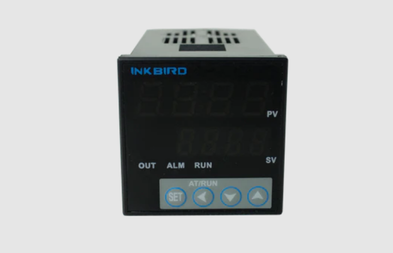
The Inkbird PID Temperature Controller ITC-106 is a versatile and precise device designed for various applications, including home brewing and temperature-sensitive processes. It features a dual display for simultaneous viewing of set and measured temperatures, with an accuracy of ±0.2% FS. The controller supports multiple thermocouples and offers both PID and ON/OFF control modes. Priced at approximately $39.99, it is an excellent choice for those seeking reliable temperature management solutions.
Specifications
Supply Voltage | AC 100~240V 50/60Hz (model:ITC-106RH, ITC-106VH) |
AC/DC 12~24V 50/60Hz (model:ITC-106RL, ITC-106VL) | |
DC 12~24V (model:ITC-106RL, ITC-106VL) | |
Operating Voltage Range | 85~110% of the rated voltage |
Power Consumption | 5VA(100~240VAC) |
| 4VA(12~24VAC) | |
| 3W(12~24VDC) | |
Display Code | PV: displays in red high luminance LED with 9.9mmheight of 4 digits |
SV: displays in green high luminance LED with 8.00mm height of 4 digits | |
| Display Accuracy | ±0.2%FS 0.1ºC/ºF(<1000ºC/ ºF);1ºC/ ºF(≥1000ºC/ ºF) |
| Sampling Period | 0.5 second |
Temperature Compensation | 0~50 ºC /32~122ºF |
Control Output | Relay Output:AC 250V 3A (resistive load) |
| Voltage Output(for driving SSR):12VDC, 30mA DC | |
| Maximum load:600Ω | |
| Electrical Life of Relay:100,000 times | |
| Alarm Output | Relay Output: AC 250V 3A (resistive load) |
| Weight | About 140g |
| Working Temperature | -10~ 55 ºC / 14~ 131 ºF(Nofreeze or condensation) |
| Working Humidity | RH 35-85% |
| Storage Temperature | -25~65ºC / -13~149 ºF (No freezeor condensation) |
Models and Specification
| Model | Control Output | Supply Voltage |
| ITC-106RL | Relay Output | AC/DC 12~24V |
| ITC-106VL | SSR Output | AC/DC 12~24V |
| ITC-106RH | Relay Output | AC 100~240V |
| ITC-106VH | SSR Output | AC 100~240V |
Safety Precautions
- Ensure the product using within the specification.
- Do not touch the terminals at least while power is being supplied. Doing so may occasionally result in injury due to electric shock.
- Do not allow pieces of metal, wire clippings, or fine metallic shaving or filings from installation to enter the product. Doing so may occasionally result in electric shock, fire, or malfunction.
- Do not use the product where subject to flammable or explosive gas. Otherwise, injury from explosion may occasionally occur.
- Never disassemble, modify or repair the product or touch any of the internal parts. Electric Shock, fire, or malfunction may occasionally occur.
- If the output relays are used past their life expectancy, contact fusing or burning may occasionally occur. Always consider the application conditions and use the output relays within their rated load and electrical life expectancy. The life expectancy of output relays varies considerably with the output load and switch conditions.
Dimension and Installing
Size Diagram (Unit: mm)

- Insert the temperature controller into the hole in the panel, put the adapter from the back and push it to button and make it clasp for temporarily fastening. Be sure there is no gap among the controller, panel and the adapter and then fasten the two screws on the adapter with the torque of 0.29N to 0.39N.
- Be sure the ambient temperature is within the stated working range in the manual, especially when there are two or more temperature controllers installed.
Wiring Diagram

- Power Connection: #9 and #10 terminals are for power connecting, which its supply voltage should be match the item model.
- Platinum Resistance Sensor Connection:
Three wires sensor: connected the #3 terminal with the red wire, the other two bule wires should be separately connected to the #4 and #5 terminals.
And the sensor with two wires (e.g. PT100) should be separately connected to the #3 and #5 terminals, the #4 and #5 terminals must be connected with the wire. - Thermocouple Connection(e.g. K sensor): #3 terminal is connected to the positive pole(Red) and the #4 terminal is connected to the negative pole(Blue).
Description
The Inkbird ITC-106 is a compact and robust temperature controller that features a user-friendly LCD display with a backlight, making it easy to read and operate even in low-light conditions. The device supports a wide range of temperature sensors, including thermocouples and thermistors, ensuring flexibility in different applications. It has dual relay outputs, allowing for both heating and cooling control, which is essential for maintaining stable temperatures in various environments.
The controller also includes alarm functions to alert users of high or low temperatures, sensor failures, and power failures, ensuring that any issues are quickly identified and addressed. Its compact design and DIN rail mounting option make it easy to integrate into existing systems.
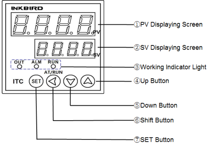
Inkbird PID Temperature Controller ITC-106 Panel Instruction

- PV Displaying Screen: Displaying the measuring value or the setting parameters.
- SV Displaying Screen: Displaying the setting value or the set parameters readout.
- Working Indicator Light
OUT: Control Output Indicating
ALM: Alarm Output Indicating
RUN: Manual Operation Indicating - UP Button: when setting the value, pressing the up button can be increase the valuethat would be added rapidly by keeping press this button.
- DOWN Button: when setting the value, pressing the down button can be decrease thevalue that would be reduced rapidly by keeping press this button.
- SHIFT Button: when setting the value or parameters,
- Pressing this button to switch to the required value position.
- Pressing this button can be shift to the submenu from the main menu.
- Pressing this button can be freely switch to another mode from manual or the automatic operation.
- SET Button: Pressing this button can read the value of control output and the settemperature. Hold and press this SET button for 3s or more can be enter into the parameters settings mode.
Setting Parameters
Sensor Type and Measuring Range

Remarks:
- The faulty input sensor is the "K" type.
- If select the wrong input sensor, the measuring temperature will be incorrect and may exceed the measuring range with displaying "orAL", control output off.
Operation Guide
Boot screen display

Enter the settings menu
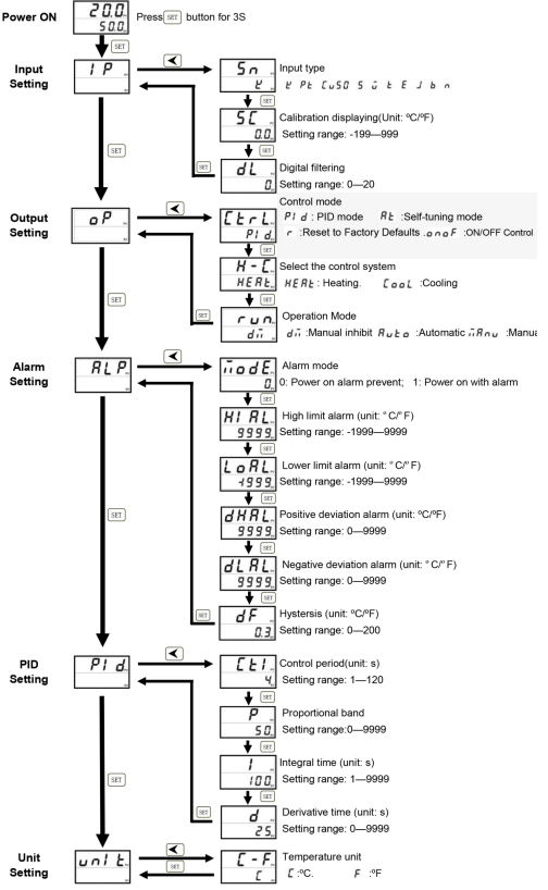
Under measuring and controlling condition, press ▲/▼ to set the temperature value, press and hold the "SET" button for 2 seconds to enter into the parameters settings mode.
Sensor Input Type Setting:
Set the sensor input type as required(the faulty is the "K" type), the temperature need to calibrated for there will be deviation due to the sensor and the operating environment.
Output Parameters Setting:
The recommended control mode for the first use is the PID control(default settings of PID control), please select the self-tuning mode when the controlling temperature cannot reach the desired value after it worked over time with the stable controlled temperature.
Under the self-tuning mode, the temperature will exceed the set value and activate the alarm. The exceeding temperature value is related to the heating system but it will return to normal after finished the self-tuning. If the temperature control requirement is undemanding, please select the ON/OFF control mode which its range of temperature controlling is depended on the dF(hysteresis).
As below is the setting and the calculation:
- The low temperature point=SV setting value-dF
- The high-temperature point=SV setting value+dF.
dF(hysteresis) can be worked both on alarm setting and ON/OFF control mode.
PID Parameters Setting:
- SSR control output: the control period(CtrL) can be set within 4 seconds(default 2 seconds);
- Relay control output: The control period (CtrL) should be set to longer time(the normal is 18s) that would prolong the work life of the relay.
Setup Flow Chart
(Please check next page)

Setup Guide
To set up the Inkbird ITC-106,
- Start by connecting the temperature sensor to the designated input port.
- Ensure that the sensor is properly calibrated and configured according to the manufacturer's instructions.
- Next, connect the heating and cooling devices to the relay output ports. Power on the controller and follow the on-screen instructions to set the desired temperature and other parameters.
- Configure the alarm settings as needed and ensure that the device is securely mounted using the DIN rail or other mounting options.
Troubleshooting
If the device fails to turn on,
- Check the power supply and ensure it is properly connected.
For inaccurate temperature readings,
- Verify that the sensor is correctly calibrated and free from damage.
If the relays are not functioning,
- Check the wiring and ensure that the heating/cooling devices are working correctly.
For alarm issues,
- Check the settings to ensure they are configured correctly.
Warranty
If you have any problems installing or using this thermostat, please carefully and thoroughly review the instruction manual. If you require assistance, please write us to [email protected]. We will reply your emails in 24 hours from Monday through Saturday.
You can also visit our web site http://www.ink-bird.com to find the answers of the common technical questions.
INKBIRD TECH. C.L. warrants this thermostat for one years from the date of purchase when operated under normal condition by the original purchaser (not transferable), against defects caused by INKBIRD’s workmanship or materials.
Pros & Cons
Pros
- Precise temperature control with PID algorithm
- Wide temperature range and high accuracy
- Dual relay output for heating and cooling control
- User-friendly interface with LCD display and backlight
- Compact design with DIN rail mounting option
- Affordable price point
Cons
- May require technical knowledge for advanced configurations
- No WiFi or Bluetooth connectivity for remote monitoring
- Sensor calibration can be time-consuming
- Limited to two relay outputs
Customer Reviews
Customers have praised the Inkbird ITC-106 for its accuracy and reliability in maintaining precise temperatures. Many users have found it easy to set up and operate, even without extensive technical knowledge. However, some users have noted that the device lacks remote monitoring capabilities and that the sensor calibration process can be somewhat complex.
Common complaints include the need for better documentation for advanced configurations and the lack of additional relay outputs for more complex systems.
Faqs
What is the temperature range of the Inkbird PID Temperature Controller ITC-106?
What types of sensors does the Inkbird support?
Does the Temperature have alarm functions?
Can I use the PID Temperature for both heating and cooling?
Is the Temperature Controller suitable for industrial use?
Why is my Controller ITC-106 not turning on?
Can I connect multiple sensors to the Controller ITC-106?
Leave a Comment
