Insteon Control KeypadLinc Relay 2487S User Guide
Content
Introduction
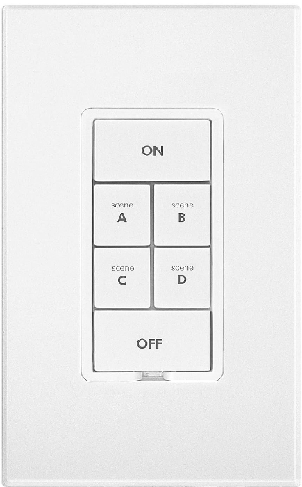
The Insteon Control KeypadLinc Relay 2487S is a multifunctional in-wall controller that combines a heavy-duty relay switch with scene control capabilities. Designed for easy installation, this device can replace a standard wall switch and allows users to manage multiple INSTEON devices with its six programmable buttons. Each button can control various lighting scenes, making it ideal for both residential and commercial settings. Priced at approximately $79.99, it enhances convenience and energy efficiency in smart home systems.
What’s in the box?
- KeypadLinc On/Off – INSTEON 6-Button Scene Control Keypad, Dual-Band
- 4 wire nuts
- 2 mounting screws
- Quick Start Guide
Specifications
- Supports up to 8 scenes or 8 individual devices
- Dual-band communication (RF and powerline)
- 6-button keypad with LED indicators
- Compatible with Insteon Hub and other Insteon devices
- Wall-mount design with a sleek and modern appearance
- Remote control capability via Insteon app or other Insteon controllers
- Energy monitoring and reporting capabilities
ABOUT KEYPADLINC On/Off
KeypadLinc On/Off (Dual-Band) is an elegant relay switch plus scene controller in one. In the 6-button configuration, the ON and OFF buttons control the connected load (light/appliance). Both the ON/OFF buttons plus the other 4 buttons can all control their own scene members (other INSTEON devices which respond to button presses on KeypadLinc). Furthermore, each button on KeypadLinc can itself be a member of countless scenes (giving you remote control of both the connected load as well as the scene buttons’ LEDs) from other INSTEON devices. KeypadLinc On/Off Dual-Band supports voltages from 120 to 277V, making it the perfect energy saving, wireless controller for commercial building automation systems.
Features and Benefits
- Easy to setup and use
- Integrated 20 amp relay (incandescent loads up to 1800 watts)
- Each button can be a scene controller
- Each button can also be a scene responder
- Each button can control the other buttons on the keypad (as well as remote devices)
- Can support up to 400 scenes
- Multiple buttons can be included in the same scene
- Each button can be configured to:
- Toggle between sending Ons and Offs (default)
- Always send an On (scene trigger mode)
- Always send an Off
- Dimmable LEDs
- Beeper
- Makes setup a breeze
- Can function as a chime module
- Configurable to beep on each button press if desired
- X10 Compatible
- Wires in like standard wall switch (requires a NEUTRAL)
- Supports 3-way, 4-way and up multi-way circuits without traveler wires
- Color change kits available
- LED color change kits available
- 8 button change kit available
- Dual-band for the ultimate in reliability
- Acts as an access point for battery powered devices
- Acts as a phase bridge
- All settings preserved through power failures
- Using software you can lockout local programming to prevent accidental changes
- Two-year warranty
Description
The Insteon Control KeypadLinc Relay 2487S is a sophisticated control device that allows users to manage their lighting and appliances with ease. The 6-button keypad provides intuitive control over multiple scenes or individual devices, making it simple to adjust lighting levels, turn appliances on/off, or activate pre-set scenes. The device features dual-band communication, ensuring reliable and robust connectivity within your Insteon network.
The LED indicators on each button provide visual feedback, helping you keep track of which devices are active. The wall-mount design ensures a clean and clutter-free installation, blending seamlessly into any home décor. This device is fully compatible with the Insteon Hub and other Insteon devices, allowing for comprehensive smart home integration.
Installation
CAUTIONS AND WARNINGS
Read and understand these instructions before installing and retain them for future reference.
KeypadLinc is intended for installation in accordance with the National Electric Code and local regulations in the United States or the Canadian Electrical Code and local regulations in Canada. Use indoors only. KeypadLinc is not designed nor approved for use on power lines other than 120VAC or 277VAC 60Hz, single phase. Attempting to use KeypadLinc on non-approved power lines may have hazardous consequences.
- Use only indoors or in an outdoor rated box
- Be sure that you have turned off the circuit breaker or removed the fuse for the circuit you are installing KeypadLinc in. Installing KeypadLinc with the power on will expose you to dangerous voltages.
- Connect only copper or copper-clad wire to KeypadLinc
- KeypadLinc may feel warm during operation. The amount of heat generated is within approved limits and poses no hazards. To minimize heat buildup, ensure that the area surrounding the rear of KeypadLinc is as clear of clutter as possible.
- Each KeypadLinc is assigned a unique INSTEON ID, which is printed on the device’s label.
- To reduce the risk of overheating and possible damage to other equipment, use KeypadLinc to control no more than 20 Amps (1800 Watts of incandescent) at 110VAC or 277VAC.
- You will need a flathead screwdriver, a Philips head screwdriver and a voltage meter to install KeypadLinc
Identifying the Electrical Wires in your Home
To install KeypadLinc, you will need to identify the following four wires:
- LINE - usually black, may also be called HOT or LIVE, carries electricity into the outlet
- LOAD (Optional) - usually black or red, feeds power to a connected lighting/appliance fixture.
- NEUTRAL - usually white
- GROUND - bare copper wire or metal fixture (if grounded)
If you are having difficulties identifying wires, consult an electrician to help you.
IMPORTANT!
If you are not knowledgeable about, and comfortable with, electrical circuitry, you should have a qualified electrician install KeypadLinc for you.
Tools Needed
- A slotted screwdriver for trim plate
- A Phillips screwdriver for KeypadLinc
- A wire cutter and stripper if the switch you are replacing requires you to cut the wires to remove them
- Voltage Tester - To identify the wires inside the junction box
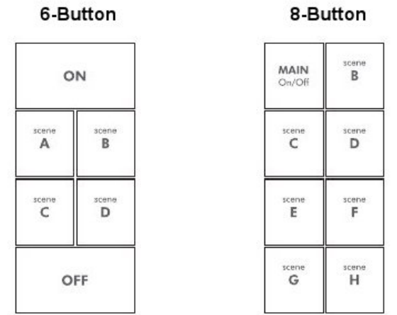
Button Naming
Throughout this manual, we will use the following naming conventions:
Installation (for a circuit with only one switch)
- At the circuit breaker or fuse panel, disconnect the power for all of the circuits in the switch junction box. Verify that the power is off by trying to turn on the lights controlled by the switches.
- Remove the trimplate from the switch junction box, and then unscrew the switch you are replacing and pull it out from the junction box
- Disconnect the wires from the switch you are replacing. If the wires cannot be detached by unscrewing them, cut the wires where they enter the switch, then strip ½” of insulation off the ends
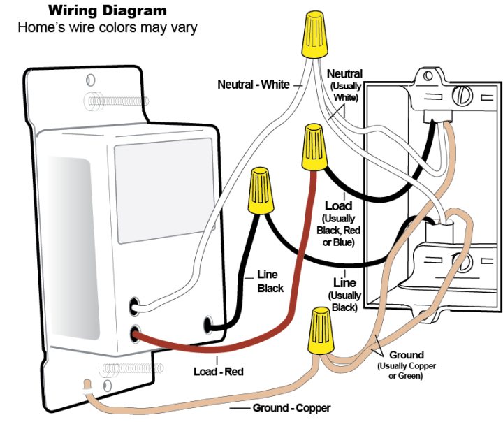
- If you are installing KeypadLinc into a standard 2-way circuit (where only one switch controls the load), follow the diagram below to identify and connect the LINE, LOAD, NEUTRAL1, and GROUND wires. If the colors of the wires do not match the diagram, be sure you have identified the wires correctly before connecting them.
- If you are installing KeypadLinc into a multi-way circuit (where more than one switch controls the load), follow the instructions in the section Installing KeypadLinc in a Multi-Way Circuit, to identify and connect the LINE, TRAVELER, NEUTRAL, and GROUND wires
- After you have connected all of the wires, ensure that all of the wire connectors are firmly attached and that there is no exposed copper except for the GROUND wire
- Orienting KeypadLinc with the Set button on the bottom, gently place it into the junction box, and then screw it into place
- Enable power to the switch from the circuit breaker or fuse panel
- Verify KeypadLinc is working properly by turning the light on and off
- Reinstall the trim plate
Installation (for a circuit with more than 1 switch)
If more than one switch controls a single set of lights (called a "load"), the switches are part of a multi-way circuit. A 3-way circuit (the most common) uses two switches to control the load, a 4-way circuit uses three switches, and so on.
Here is how a typical wired-in, 3-way circuit (with two switches) works:
_insteon_control_keypadlinc_relay_2487s.png)
A wired-in 4 or more-way circuit (with three or more switches) has additional switches added in the middle of the circuit. In the diagram below, the additional switch (Switch 3+) is shown in two different positions since wiring can vary from home to home.
-insteon_control_keypadlinc_relay_2487s.png)
To learn more about multi-way circuits, try Googling the search terms "3-way switch" or "4-way switch."
Using KeypadLinc in Virtual Multi-Way Circuits
By creating virtual, multi-way circuits, you can use KeypadLincs to replace switches in 3-way, 4-way and higher multi-way circuits that are already wired into your home. Or, you can use them to create multi-way circuits where there is no existing, multi-way wiring thus saving the hassle and expense of re-wiring.
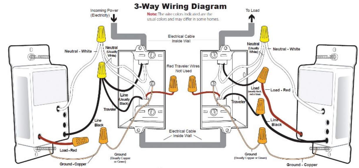
In a virtual multi-way circuit, only one KeypadLinc, called the KeypadLinc Primary, actually connects to the load in the multi-way circuit. Additional KeypadLincs, called KeypadLinc Secondaries, are not connected to the load, but only to power (LINE and NEUTRAL wires). All of the KeypadLincs communicate with the others using INSTEON. After wiring in the KeypadLincs, you can create the virtual multi-way circuit by setting up all of the KeypadLincs (or KeypadLinc and switches) to control each other (see Control Groups). The diagram below shows a previously wired 3-way circuit, now a virtual 3-way circuit using a KeypadLinc plus other INSTEON switch or keypad.
Notes:
- One of the TRAVELER wires (TRAVELER 1, Red) is not used, so you will cap it off at both ends
- The other TRAVELER (TRAVELER 2, Black) you will convert to a LINE wire. In the Secondary KeypadLinc’s junction box, connect TRAVELER 2 to the existing LINE and also to the KeypadLinc Secondary’s LINE wire. In the other junction box at the other end, you will connect TRAVELER 2 to the KeypadLinc Primary’s LINE wire.
- The KeypadLinc Primary’s LOAD wire gets connected to the actual lights that are being controlled
- The LOAD wire for any KeypadLinc Secondaries that you will be installing will not be connected to anything, so cap those LOAD wires off with a wire nut
- All KeypadLincs, whether they are Primaries or Secondaries, must be connected to NEUTRAL and to GROUND. You may notice that the switches you are replacing will not normally have a connection to NEUTRAL. KeypadLinc will not function without a NEUTRAL.
Step-by-Step Instructions For Installing Multi-Way KeypadLinc Switches
When replacing a 3-way mechanical switch, each switch will have three wires connected to it from the wall box. Four-way or greater circuits will have four wires connected to the switches in the center of the circuit. For this tutorial, we will follow the most commonly used wire colors for homes in North America.
Find the LINE wire. Your first task is to find out which switch junction box is the one where the electricity comes into the circuit. This box will contain the LINE wire.
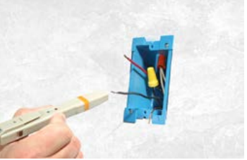
- Disable power at the circuit breaker or fuse panel
- Pull all the switches in the multi-way circuit out of their junction boxes.
Each switch should have three wires connected to it. If the circuit is 4- way or greater, some of the switches will have four wires. - Disconnect the wires from the old switches. If the wires cannot be detached by unscrewing them, cut the wires where they enter the switch and then strip ½ inch of insulation off the ends.
- Make sure that none of the wires are touching anything and turn the electricity back on
- Using a volt meter or voltage tester, individually test each wire for voltage. When you measure between 110 and 120 Volts AC, that wire is the LINE wire (usually black).
- The other two wires (usually black and red) are the TRAVELERS and go to the next junction box. TRAVELER wires are usually in the same cable sheath.
- Turn off the electricity to resume installation
- Connect the KeypadLinc Secondary’s LINE wire. The KeypadLinc that will be the Secondary goes in the junction box where you found the LINE wire. Connect the LINE wire that you found, the black TRAVELER, and the KeypadLinc Secondary’s black LINE wire all together with a single wire nut.
- Cap the other TRAVELER wire. The other TRAVELER wire (usually red) will not be used, so put a wire nut on the end of it.
Cap the red LOAD wire from the KeypadLinc Secondary. Put a wire nut on the end of the KeypadLinc Secondary’s LOAD wire to ensure that it won’t connect to anything.
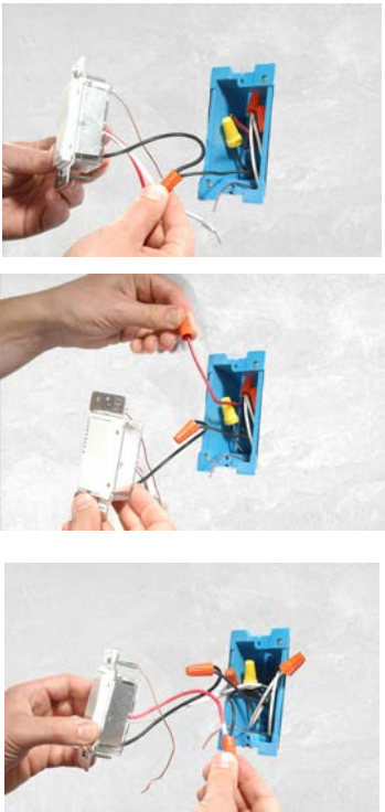
- Connect the KeypadLinc Secondary’s NEUTRAL wire. Locate the group of NEUTRAL wires (usually white) in the rear of the box. The old switch should not have been connected to the NEUTRAL wires, but KeypadLinc requires this connection in order to draw a small amount of power for itself. Connect the KeypadLinc Secondary’s white NEUTRAL wire to the other NEUTRAL wires with a wire nut.
Connect the KeypadLinc Secondary’s GROUND Wire. Connect the bare copper GROUND wire to the other GROUND wire in the junction box.
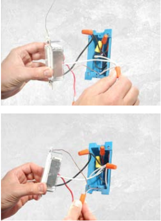
- Install additional switch/keypad Secondaries. If you have a 4-way or greater switching circuit, see Special Instructions For Large Multi-Way Circuits at the end of this section.
- Identify the wires for the KeypadLinc Primary. The KeypadLinc Primary is the KeypadLinc that will actually control the load. In the junction box where you will install the KeypadLinc Primary, find the wire that carries power from the switch to the lights. This wire, called the LOAD wire, is commonly red.
In the same junction box, there will also be the two TRAVELER wires from the first box, often both in the same cable sheath. Identify the TRAVELER wire (black) that you connected the LINE wire to in the first junction box.
If you’re not sure which is the TRAVELER wire connected to the LINE wire, you can use the same method described in step 1 to find it. Turn on the power (taking the same precautions) and use a voltmeter to find the wire with 120 Volts AC on it.
Make sure the power is turned off again before proceeding. - Connect the KeypadLinc Primary’s LINE wire. Use a wire nut to connect the TRAVELER wire (usually black) that you identified as connected to the LINE wire to the KeypadLinc Primary’s black LINE wire.
- Cap the other TRAVELER wire. The other TRAVELER wire (usually red) will not be used, so put a wire nut on the end of it.
- Connect the KeypadLinc Primary’s LOAD wire. Use a wire nut to connect the LOAD wire (usually red) to the KeypadLinc Primary’s red LOAD wire.
Connect the KeypadLinc Primary’s NEUTRAL and GROUND wires. Repeat steps 5 and 6 with the KeypadLinc Secondary.
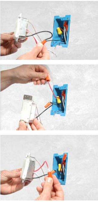
- Finish installation. Return to Installing KeypadLinc and continue on from step 5.
- Refer to Control Groups for instructions on scene setup
Special Instructions For Large Multi-Way Circuits
If your lighting circuit includes more than two switches controlling a single set of lights, those extra switches will have four wires connected to them. Two of the wires are TRAVELERS from the preceding switch and the other two are TRAVELERS to the next switch in the chain. You will be converting the black TRAVELER wires to the LINE wires and replacing the old 4-wire switches with KeypadLinc Secondaries.

- Connect the KeypadLinc Secondary’s LINE Wire. Use a wire nut to connect both black TRAVELER wires to the KeypadLinc Primary’s black LINE wire.
- Cap the two unused TRAVELERS. The other two TRAVELER wires (usually red) will not be used, so put wire nuts on the ends of them.
- Cap the red LOAD wire from the KeypadLinc Secondary. Put a wire nut on the end of the KeypadLinc Secondary’s LOAD wire to ensure that it won’t connect to anything.
- Connect the KeypadLinc Secondary’s NEUTRAL and GROUND wires. Repeat steps 5 and 6 of Step-by Step Instructions for Installing Multi-Way KeypadLincs.
USING KEYPADLINC
Button Taps
Button Type | Button’s LED | Tap | Double-tap |
Toggle | Off | Turn SceneOn | Turn SceneMembers On Instantly |
Toggle | On | Turn SceneOff | Turn SceneMembers Off Instantly |
Always On | Either | Turn SceneOn | Turn SceneMembers On Instantly |
Always Off | Either | Turn SceneOff | Turn SceneMembers Off Instantly |
Press and Holds
Button Type | Button’s LED | First Press and Hold | Subsequent Press and Holds |
Toggle |
Off | Brighten Sceneuntil release | Opposite of last Press and Hold (e.g. if last was brightening, it will dim) |
Toggle |
On | Dim Scene until release | Opposite of last Press and Hold (e.g. if last was brightening, it will dim) |
Always On | Either | Brighten Sceneuntil release | |
Always Off | Either | Dim Sceneuntil release | |
Notes:
- The Load will react just like the scene responders to button presses of MAIN when in 8-Button configuration
- The LED will mimic the on/off status of a dimmer whose scene level is 100% bright
INSTEON Scenes
Scene: One or more INSTEON devices which respond simultaneously to scene commands (e.g. button presses). When the scene is activated (turned “on”), all devices return to the states they were at when the scene was programmed. INSTEON scenes let you activate dramatic lighting moods at the touch of a button. For example, you can set all the lights in a scene to dim to 50% or turn certain lights on while turning others off. INSTEON scenes are easy to set up, just follow the directions below.
The below diagram provides an overview of the options available in the KeypadLinc Setup Mode and how to navigate between the options. The Advanced Setup Features are highlighted in yellow.
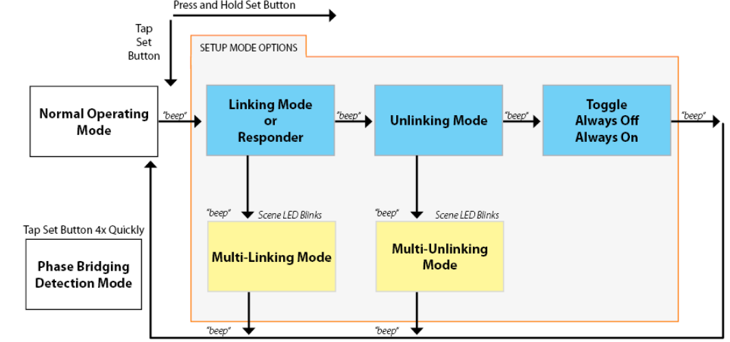
- Tap the scene button you wish to setup before entering setup mode
- Advanced setup features are highlighted in yellow
- Toggle: Cycles automatically between “Toggle”, “Always Off”, “Always On” upon entry into this mode, then exists to Normal Operating Mode
Add KeypadLinc Button to a Scene as a Controller (also known as Linking Mode)
- Tap the KeypadLinc Scene button of choice (doesn’t matter if you send an on or an off)
- Press and hold KeypadLinc’s Set button until it beeps
KeypadLinc’s scene button’s LED will blink
All illuminated LEDs on KeypadLinc will brighten to 100%
You will have 4 minutes to complete the next step before Linking Mode automatically times out. - Adjust the scene responder to the “state” you wish it to be at when the Scene is activated from KeypadLinc (e.g. 50%, 25% or even OFF)2 (Note: manual tap of responder button/paddle/etc. is required)
- Press and hold the Responder’s Set button until it beeps (or until its LED/load flashes)
KeypadLinc will double-beep and its scene button’s LED will stop blinking
KeypadLinc’s LEDs will return to normal brightness
Responder’s LED will stop blinking (it may also double-beep) - Confirm that Scene addition was successful by tapping on/off on your chosen KeypadLinc button
The Responder will toggle between the Scene level and Off - If you wish to add more responders to KeypadLinc, repeat steps 1-5 for each additional scene responder (or see Add Multiple Scene Responders at Once)
Add KeypadLinc Button to a Scene as a Responder (also known as Responder Setup)
- Press and hold the Scene Controller (the other INSTEON device) button until it beeps3
Controller’s LED will blink - When the scene is activated
- If you want the LED4 ON
- Tap KeypadLinc’s Scene Responder button until LED is on
- If you want the LED OFF
- Tap KeypadLinc’s Scene Responder button until LED is off
- If you want the LED4 ON
- Press and hold KeypadLinc’s Set button until it double-beeps
KeypadLinc’s scene button’s LED will flash once and return to its previous state
Controller will (Beep)-(Beep)5 and its LED will stop blinking - Confirm that Scene addition was successful by tapping on then off on the controller’s scene button
KeypadLinc’s scene button’s LED will toggle between On and Off
Remove KeypadLinc Button from a Scene as a Responder (also known as Responder Setup)
Note: If you are going to discontinue using KeypadLinc, it is very important that you remove it from all of its scene controllers. Otherwise, the controllers will retry commands repetitively and creating network delays.
- Press and hold the Controller’s Scene button
- Press and hold the Controller’s Set button until it beeps6 (or LED blinks)
Controller’s LED blinking - Press and hold the Controller’s Set button until Controller beeps again6 (5 seconds if no beeper)
Controller’s LED blinking - Tap KeypadLinc’s Responder Button you are removing
- Press and hold Set button on KeypadLinc until it double-beeps
KeypadLinc’s scene button’s LED will flash once and return to previous state Controller will (Beep)-(Beep)7 and its LED will stop blinking - Confirm that Unlinking was successful by tapping the Controller’s scene button a couple times
KeypadLinc will no longer respond
Removing KeypadLinc from a Scene as a Controller (also known as Unlinking Mode)
Note: If you are no longer going to use a scene responder of KeypadLinc, it is very important that you remove its scene membership. Otherwise, KeypadLinc will retry every scene command repetitively, thus creating network delays.
- Tap the scene button on KeypadLinc
- 3 If the controller does not have a beeper, wait until its LED begins blinking
- 4 Load will mimic LED state for toggle buttons, for the ON and OFF buttons tap the desired scene state 5 Most models
- 6 For devices without beepers hold until its LED begins blinking (this may take 10+ seconds)
- 7 Most models
- Press and hold KeypadLinc’s Set button until it beeps
KeypadLinc’s LED will begin blinking
All illuminated LEDs on KeypadLinc will brighten to 100% - Press and hold the KeypadLinc’s Set button until it beeps again
KeypadLinc’s LED will continue blinking - If responder has multiple buttons, tap the button you wish to remove from scene
- Press and hold the Responder’s Set button until it double-beeps (or LEDS blink)
KeypadLinc will (Beep)-(Beep) and its scene LED will stop blinking
KeypadLinc’s LEDs will return to normal brightness
Responder will (Beep)-(Beep) and its LED will flash once - Confirm that Unlinking was successful by tapping the scene button on KeypadLinc a couple times
The Responder will not respond
Air Gap
The "air gap" removes power from the connected load (controlled circuit) when pulled out. This is handy for replacing bulbs without turning off the circuit breaker.
Disable Power:
To disable power, pull the Set button at the bottom of the switch out as far as it will go, about 1/8 inch. (It might be helpful to use a small screwdriver.) This will open the mechanical contacts and will remove all power to the INSTEON device and the load that it controls until the Set button is pushed back in. However, because the INSTEON device's settings are stored in non-volatile memory, setup information will not be lost when the unit is unpowered. IMPORTANT: Make sure circuit is off by observing light going off (if possible) and LEDs on KeypadLinc turning off before performing work on the switched circuit.
Restore Power:
To restore power, tap the air gap back into place, until its top is even with the trim frame.
Important: Do not hold the Set Button in for more than a second. If held in longer, you may inadvertently perform a factory reset.
Changing a KeypadLinc Button
KeypadLinc buttons may be changed to customize appearance. Please use care – the button frame can be damaged and/or broken during this process. Using a small, slotted screwdriver (ONLY) pry up on the sides of the keys from the middle of the keypad (as shown). Make sure you are centered on the key as there is a small “lip” to pull up on located there. The large buttons have a small "lip" on the left and right side.

ADVANCED FEATURES
Using KeypadLinc as a Phase Bridge (Phase Bridging Detection Mode)
KeypadLinc automatically bridges the electrical phases in your home (via communications with dual-band devices on the “other phase”). The following procedure to confirm that phases are bridged via KeypadLinc:
- Start Phase Bridging Detection Mode by tapping the Set button on KeypadLinc four times quickly
KeypadLinc will begin (Beeping)
KeypadLinc LEDs that are on will illuminate at full brightness
Other dual-band devices' LEDs will illuminate at 100% brightness - Check the LED behavior of the “other” dual-band devices
- If the “other” dual-band device is blinking green8
- it is within range and not on the same phase, proceed to next Step
- If they are not blinking green9
- Try moving the “other” device, check other dual-band devices or begin test from a different initiator
- If the “other” dual-band device is blinking green8
- Tap KeypadLinc’s Set Button
KeypadLinc will stop beeping and LEDs return to previous state
Other devices’ LEDs will stop blinking
Add Multiple Scene Responders at Once (also known as Multi-Linking Mode)
- Set each of the Responders to the desired scene activation state10
- Tap the Scene controller button on KeypadLinc
- Press and hold KeypadLinc’s Set Button until it beeps
KeypadLinc’s scene button’s LED will begin blinking
All illuminated LEDs on KeypadLinc will brighten to 100% - Tap KeypadLinc’s Set Button
KeypadLinc’s scene button’s LED will continue blinking - For each responder you are adding:
- Tap the responder button (if it is a multi-button device)
- Press and hold set button until it beeps (or, about 3 seconds until LED flashes)One at a time, press and hold each of the Responder’s Set buttons for 3 seconds
- Tap KeypadLinc’s Set Button
KeypadLinc’s scene button’s LED will stop blinking
KeypadLinc’s LEDs will return to normal brightness - Test scene by tapping the scene button a couple of times
- Or is simply blinking for single colored LEDs. If the “other” dual-band device is a KeypadLinc Dual-Band, the 4 middle LEDs will blink.
- Or are not blinking at all for single colored LEDs. If the “other” dual-band device is a KeypadLinc, any LEDs that are on will go to full bright.
- For KeypadLinc buttons, tap the button until its LED is in the desired scene activation state
All the responders added above should respond to scene activations
Remove Multiple Scene Responders at Once (also known as Multi-Unlinking Mode)
- Tap the Scene controller button on KeypadLinc
- Press and hold KeypadLinc’s Set Button until it beeps
KeypadLinc’s scene button’s LED will begin blinking
All illuminated LEDs on KeypadLinc will brighten to 100% - Press and hold KeypadLinc’s Set Button again until it beeps again
KeypadLinc’s scene button’s LED will continue blinking - Tap KeypadLinc’s Set Button
KeypadLinc’s scene button’s LED will continue blinking - For each responder you are removing
- Tap the responder button (if it is a multi-button device)
- Press and hold set button until it beeps (or, about 3 seconds until LED flashes). One at a time, press and hold each of the Responder’s Set buttons for 3 seconds.
- Tap KeypadLinc’s Set Button
KeypadLinc’s scene button’s LED will stop blinking
KeypadLinc’s LEDs will return to normal brightness - Test scene by tapping the scene button a couple of times
All the responders added above should respond to scene activations
Control Groups (also known as Cross-Linking)
Control groups will all respond the same to all scene activations and de-activations (off’s). A common example is a 3-way lighting circuit. 4-way lighting circuits as well as scenes with multiple controllers and only 1 “load bearing” responder are also examples of control groups.
3-Way Circuit Example (a Control Group with 2 members)
- Turn both switches/dimmers on – to the same, desired scene level
- Press and hold Switch A’s set button until it beeps (or LED blinks)
Switch A’s LED will begin blinking - Press and hold Switch B’s set button until it double-beeps (or LED flashes)
Switch B will (Beep)-(Beep) and its LED will flash once
Switch A will (Beep)-(Beep) and its LED will stop blinking - Press and hold Switch B’s set button until it beeps (or LED blinks)
Switch B’s LED will begin blinking - Press and hold Switch A’s set button until it double-beeps (or LED flashes)
Switch A will (Beep)-(Beep) and its LED will flash once
Switch B will (Beep)-(Beep) and its LED will stop blinking - Test the group by controlling the load from Switch A and then Switch B
The Load, Switch A and Switch B will all remain in synch
Control Groups with more than 2 members
Software is recommended for larger control groups. However, the following steps, when carefully followed, will also work.
- Turn all N switches/dimmers on – to the same, desired scene level
- Press and hold Switch A’s set button until it beeps (or LED blinks)
Switch A’s LED will begin blinking - Tap Switch A’s set button
- Press and hold Switch B’s set button until it double-beeps (or LED flashes)
Switch B will (Beep)-(Beep) and its LED will flash once - Repeat prior step for Switch C, Switch D……….Switch N
Each Switch will (Beep)-(Beep) and its LED will flash once - Tap Switch A’s set button
- Repeat Steps 2-5 for Switches B through N
- Test the group by controlling the load from each switch
The Load(s) and all the switches will all remain in synch
Setup Guide
To set up the Insteon Control KeypadLinc Relay 2487S,
- Start by mounting the device to your wall using the provided mounting clips.
- Connect the device to your electrical wiring according to the instructions in the user manual.
- Once installed, pair the KeypadLinc Relay with your Insteon Hub or other Insteon controllers using the Insteon pairing process.
- Configure the buttons on the keypad to control specific devices or scenes using the Insteon app or through the device itself. Ensure that all devices are properly linked and configured for seamless operation.
Changing Button Behavior (Toggle / Non-Toggle Mode)
You can change any button, except the dedicated On/Off buttons, to any one of three Button Modes:
- Toggle (default) – toggles between ON and OFF commands each time it is pressed
- Always Off – sends ON every time it is pressed
- Always On – sends OFF every time it is pressed
To change the Button Mode
- Tap the desired button
- Press and hold KeypadLinc’s Set button until it beeps
The button’s LED will begin blinking
All illuminated LEDs on KeypadLinc will brighten to 100% - Press and hold KeypadLinc’s Set button a 2nd time until it beeps a 2nd time
The button’s LED will continue blinking - Press and hold KeypadLinc’s Set button a 3rd time until it beeps a 3rd time
The button’s LED will stop blinking
The button rotates to the next Button Mode in the cycle:- Toggle → Always Off
- Always Off → Always On
- Always On → Toggle
- If you wish to rotate KeypadLinc to the next Button Mode in the cycle, repeat steps 2-4
“Radio” Button Groups (only 1 LED of “n” at a time)
This feature is especially handy if you have multiple scenes controlling the same devices, such as Lights Bright, Lights Medium and Lights Off. When you press any of the scene buttons, the “others” LEDs will turn off (as if they were scene responders). Because of their complexity, software is recommended for radio button group setup.
- Tap each radio group button until its LED is On
- Press and hold button A until it beeps (about 10 seconds)
- Press and hold button B until it beeps (about 10 seconds)
- If you are grouping more than 2 buttons
- Repeat steps 1-3 inserting buttons C, D, etc. into Step 3
- Repeat steps 1-4, inserting button B into step 2 and all other buttons into step 3 (and 4)
- Tap each radio group button until its LED is Off
- Press and hold button A until it beeps (about 10 seconds)
- Press and hold button B until it beeps (about 10 seconds)
- If you are grouping more than 2 buttons
- Repeat steps 6-8 inserting buttons C, D, etc. into Step 8
- Repeat steps 6-9, inserting button B into step 7 and all other buttons into step 8 (and 9)
Adjust LED Brightness
KeypadLinc’s LEDs can be set to any one of 32 brightness levels.
If KeypadLinc in 6-Button Configuration
- Simultaneously tap the A and D buttons
KeypadLinc will beep - Use the On and Off buttons to adjust the LED brightness
- When you have reached the desired brightness, simultaneously tap the A and D buttons again
KeypadLinc will beep
If KeypadLinc in 8-Button Configuration
- Simultaneously tap the C and F buttons
KeypadLinc will beep - Press and hold the On button to adjust the LED brightness. (The button will toggle between brightening and dimming.)
- When you have reached the desired brightness, simultaneously tap the C and F buttons
KeypadLinc will beep
Turn Button Beep On or Off
The KeypadLinc buttons can be set to Beep Mode so KeypadLinc will beep every time a button is used. By default, Beep Mode is off.
If KeypadLinc in 6-Button Configuration
- Simultaneously tap the B and C buttons
KeypadLinc will beep
Keypad’s Beeper will toggle to on (if was off) or off (if it was on)
If KeypadLinc in 8-Button Configuration
- Simultaneously tap the D and E buttons
KeypadLinc will beep
Keypad’s Beeper will toggle to on (if was off) or off (if it was on)
Power Restore
KeypadLinc stores all of its scenes, properties, etc. in non-volatile memory. As such, all settings are retained after a power outage. Upon power being restored, KeypadLinc will return its connected load and all LEDs to their states prior to power outage.
Add X10 Address to a Button
- Tap the KeypadLinc button
- Press and hold KeypadLinc’s Set button until it beeps
The button’s LED will begin blinking - Send the desired X10 Address, plus ON, 3 times (e.g. send B5, BON, B5, BON, B5, BON)
KeypadLinc will double-beep and the button’s LED will stop blinking
Remove X10 Address from a Button
If you are no longer going to control KeypadLinc with an X10 address, it is very important that you remove its X10 address. Otherwise, KeypadLinc will still listen for X10 commands (somewhat hindering INSTEON reception) and may respond to spurious X10 “noise” which is unavoidable.
- Tap the KeypadLinc button of choice
- Press and hold KeypadLinc’s Set button until it beeps
The button’s LED will begin blinking - Press and hold KeypadLinc’s Set button again until it beeps again
The button’s LED will continue blinking - Send the X10 Address, plus ON, 3 times (e.g. send B5, BON, B5, BON, B5, BON)
KeypadLinc will double-beep and the button’s LED will stop blinking
Advanced X10 Programming
Instructions on setting X10 primary address and scene addresses can be found online: http://www.insteon.com/insteon-x10-programming.html
Factory Reset
Factory Reset clears all user settings from KeypadLinc including INSTEON Scenes, On-Levels, Ramp Rates, X10 addresses, etc.
- Pull Set button out (creating an Air Gap)
- Wait 10 Seconds
- Push Set Button in and Hold it in
KeypadLinc will (Beep) - Release the Set button
Device’s embedded software will re-write all settings to factory defaults
A couple of seconds will pass
KeypadLinc will (Beep)-(Beep)
LEDs will return to normal brightness
KeypadLinc returns to Ready Mode
The connected load will turn on
Troubleshooting
If you encounter issues with your Insteon Control KeypadLinc Relay 2487S,
- Check for common problems such as poor connectivity or misconfiguration.
- Ensure that all devices are properly paired and linked within your Insteon network.
- If buttons are not responding, try resetting the device or re-pairing it with your Insteon Hub.
- For more complex issues, refer to the user manual or contact Insteon customer support.
- Always follow safety instructions when working with electrical devices to avoid any potential hazards.
Problem | Possible Cause | Solution |
The indicator lightsunder the KeypadLinc buttons are not illuminated. The KeypadLinc is not controlling the load. |
KeypadLinc may not be getting power. | Make sure the circuit breaker is turned on. |
Make sure theair gap (Setbutton) is not pulled out. | ||
Check the junction boxwires to ensureall connections are tight and no bare wires are exposed. | ||
Make sure the Lineand Load wireare not mis-wired inside the junction box. | ||
Check the connected load to ensureall connections are tight and no bare wires are exposed. | ||
KeypadLincwon’t Link or work with a Controller or Responder. | The Controller or Responder might have been reset without Unlinking KeypadLinc from it. |
Re-Link KeypadLinc to the Controller or Responder. |
The Controller or Responder and KeypadLinc may be on opposite power line phases. | Make sure two dual-band INSTEON devices are properly installed to bridge thetwo power linephases. | |
The INSTEON signalmay be too weak. | Add additional INSTEON devices or move around existing INSTEON devices. All INSTEON devices act as INSTEON networkrepeaters to improve communication signals. |
Large appliances, such as refrigerators or air conditioners, may be producing electrical noise on the power line. |
Install a powerline noise filter(like FilterLinc™ #1626- 10) on the inferring electrical device to filter-out the electrical noise and minimize signal attenuation. | |
Other electrical devices, such as computers, televisions, or power strips, may be absorbing the INSTEON signal. | ||
KeypadLinc is taking a long timeto respond to a Controller. | The Controller may be sending commands to a Responder that is no longer in use. Commands for the unused Responder are being resent and slowing down communication signals to KeypadLinc. | Unlink any unused Responders from the Controller. HINT: If you are usinghome automation software, you can easily check scene membership and eliminate unnecessary Links. |
If the abovedoesn’t work, perform a factory reseton the Controller. | ||
Respondersare taking a long time to respond to KeypadLinc. |
KeypadLincmay be sending commands to a Responder that is no longer in use. Commands for the unused Responder are being resent and loading down the signal. | Unlink any unused Responders from KeypadLinc. HINT: If you are usinghome automation software, you can easily check scene membership and eliminate unnecessary Links. |
If the abovedoesn’t work, performa factory reset.See | ||
The load turnedon by itself. | Another Controller, a timer, or stray X10 signals could have triggered KeypadLinc. |
Perform a factoryreset. See Resetting KeypadLinc to its Factory Default Settings. |
KeypadLinc can turn off a Responder but nothing happens when I send an ON command from KeypadLinc. | The Responder may be Linked at its load-off state (whenever an On or OFF command is received, the unit always goes to OFF). |
Re-Link the Responder to KeypadLinc, while the Responder’s load is on. See the Responder’s Owner’s Manual for more detailed Linking instructions. |
The Controller can turn off KeypadLinc but KeypadLinc does not turn on when I sendan ON command fromthe Controller. |
KeypadLincmay be Linkedat its off state. |
Re-Link KeypadLinc to the Controller, while the load is on. See Linkingan INSTEON Controller to KeypadLinc . |
KeypadLinc is locked up or operating strangely. |
A surge or excessive noise on the power line may have glitched it. | Pull the Set buttonon KeypadLinc allthe way out to air gap it (disconnect it from electricity) and then push it back in until it is flush with the trimplate. |
If the above doesn’t work, perform a factory reset.See | ||
I can remotely turn on the load connected to the KeypadLinc, but it is difficult to turn off. |
The connected load may be producing too much electrical noise when on making it difficult for KeypadLinc to detect an OFF signal through the AC power lines. | Install a noise filter between the KeypadLinc Load wire and the connected load. The filterworks best whenit is installed closest to the noisy load. |
Increase thestrength of the INSTEON communication signal by adding more INSTEON products or use Access Point and dual-band products to get signal to KeypadLinc by wireless communications. |
The KeypadLinc is turning itselfon and off every few seconds. | The Line and Load wiresmay be swapped | Double check the wiring connection. Be sure of the wires in the junction are correctly connected to the Line, Load, and Neutral wires. |
Pros & Cons
Pros
- Easy to install and configure
- Intuitive 6-button keypad for multiple device control
- Dual-band communication for reliable connectivity
- Compatible with a wide range of Insteon devices
- Sleek and modern wall-mount design
- Energy monitoring and reporting capabilities
Cons
- Requires an Insteon Hub for full functionality
- May require additional setup for complex scenes
- Some users find the LED indicators too bright
- Limited customization options for button assignments
Customer Reviews
Customers have generally praised the Insteon Control KeypadLinc Relay 2487S for its ease of use and robust features. Many appreciate the intuitive keypad interface and the ability to control multiple devices from a single location. However, some users have noted that the setup process can be slightly complex, especially for those new to smart home automation.
The most common complaints include the need for an Insteon Hub for full functionality and some minor issues with button customization. Overall, the device has received positive feedback for its performance and integration within the Insteon ecosystem.
Faqs
How do I pair the Relay 2487S with my Insteon?
Can I use the Insteon Control without an Insteon?
How many devices can I control with the Insteon?
Is the Insteon Control compatible with other smart home systems?
How do I reset the Insteon Control Relay?
Can I customize the button assignments on the Insteon?
Does the Insteon support energy monitoring?
Is the Insteon Control KeypadLinc Relay 2487S easy to install?
Leave a Comment
