Itech DC Programmable Electronic Loads IT8500 plus User Manual
Content
Brief Introduction
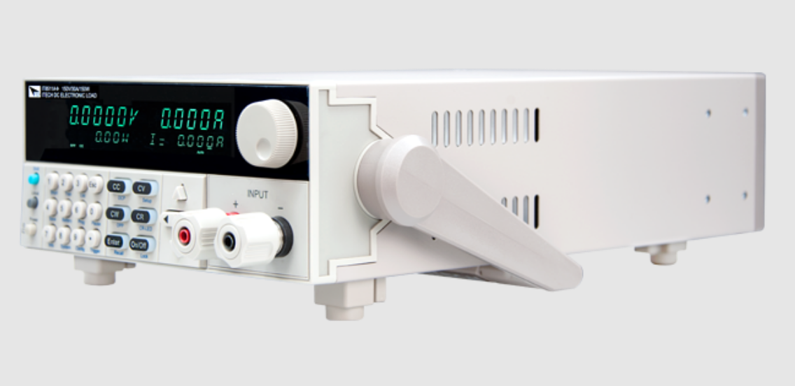
DC Programmable Electronic Loads IT8500 plus series is a single-channel programmable electronic load. With power ranges from 150W to 3000W. The user can perform online voltage measurements and adjustments or simulate short circuit test using the simple keypad on the front panel. IT8500+ also offers a full-featured battery mode for discharging test. IT8500+ series DC load is a versatile instrument for static and dynamic testing of power supplies, batteries, AC-DC/DC-DC converters, battery chargers, provides user the best testing solution.
Model | Voltage | Current | Power | Communication Interface |
IT8511+ | 120V | 30A | 150W | DB9(TTL) |
IT8511A+ | 150V | 30A | 150W | DB9(TTL) |
IT8511B+ | 500V | 10A | 150W | DB9(TTL) |
IT8512+ | 120V | 30A | 300W | DB9(TTL) |
IT8512A+ | 150V | 30A | 300W | DB9(TTL) |
IT8512B+ | 500V | 15A | 300W | DB9(TTL) |
IT8512C+ | 120V | 60A | 300W | DB9(TTL) |
IT8512H+ | 800V | 5A | 300W | DB9(TTL) |
IT8513A+ | 150V | 60A | 400W | DB9(TTL) |
IT8513B+ | 500V | 30A | 600W | Standard USB/RS232 |
IT8513C+ | 120V | 120A | 600W | DB9(TTL) |
IT8514B+ | 500V | 60A | 1500W | Standard USB/RS232 |
IT8514C+ | 120V | 240A | 1500W | Standard USB/RS232 |
IT8516C+ | 120V | 240A | 3000W | Standard USB/RS232 |
Detailed Specifications
Model | IT8511+ | ||||
Rated value ( 0~40 ℃) | Input voltage | 0~120V | |||
Input current | 0~3A | 0~30A | |||
Input power | 150W | ||||
Minimum operation value |
0.14V at 3A |
1.4V at 30A | |||
CV mode | Range | 0.1~18V | 0.1~120V | ||
Resolution | 1mV | 10mV | |||
Accuracy | ±(0.05%+0.02%FS) | ±(0.05%+0.025%FS) | |||
CC mode | Range | 0~3A | 0~30A | ||
Resolution | 0.1mA | 1mA | |||
Accuracy | ±(0.05%+0.05%FS) | ±(0.05%+0.05%FS) | |||
CR mode *1 | Range | 0.05Ω~10Ω | 10Ω~7.5KΩ | ||
Resolution | 16bit | ||||
Accuracy | 0.01%+0.08S *2 | 0.01%+0.0008S | |||
CP mode *3 | Range | 150W | |||
Resolution | 10mW | ||||
Accuracy | ±(0.1%+0.2%FS) | ||||
Dynamic mode | |||||
Dynamic mode | CC mode | ||||
T1&T2 | 20uS~3600S /Res:1uS | ||||
Accuracy | 2uS±100ppm | ||||
Rising/Falling slope *4 | 0.0001~0.2A/uS | 0.001~1.5A/uS | |||
Minimum rise time *5 | ≒10uS | ≒10uS | |||
Measuring range | |||||
Readback voltage | Range | 0~18V | 0~120V | ||
Resolution | 0.1 mV | 1 mV | |||
Accuracy | ±(0.025%+0.025%FS) | ±(0.025%+0.025%FS) | |||
Readback current | Range | 0~3A | 0~30A | ||
Resolution | 0.1mA | 1mA | |||
Accuracy | ±(0.05%+0.05%FS) | ||||
Readback power | Range | 150W | |||
Resolution | 10mW | ||||
Accuracy | ±(0.1%+0.2%FS) | ||||
Protection range | |||||
OPP Protection | ≒160W | ||||
OCP Protection | ≒3.3A | ≒33A | |||
OVP Protection | ≒125V | ||||
OTP Protection | ≒85℃ | ||||
Specification | |||||
Short | Current( CC ) | ≒3.3/3A | ≒33/30A | ||
Voltage( CV ) | 0V | 0V | |
Resistance( CR ) | ≒45mΩ | ≒45mΩ | |
Input Impendance | 150KΩ | ||
Dimension | 214.5mm*88.2mm*354.6mm | ||
- The voltage/current input is no less than 10% FS
- The scope of read back resistance is: (1/(1/R+(1/R)*0.01%+0.08),1/(1/R --(1/R)* 0.08))
- The voltage/current input is no less than 10% FS
- A cending/descending slope: 10% 90% current ascending slope from 0 to maximum current.
- Minimum rise time: 10% 90% current rise time
Model | IT8512+ | ||
Rated value ( 0~40 ℃) | Input voltage | 0~120V | |
Input current | 0~3A | 0~30A | |
Input power | 300W | ||
Minimum operation value |
0.12V at 3A |
1.2V at 30A | |
CV mode | Range | 0.1~18V | 0.1~120V |
Resolution | 1mV | 10mV | |
Accuracy | ±(0.05%+0.02%FS) | ±(0.05%+0.025%FS) | |
CC mode | Range | 0~3A | 0~30A |
Resolution | 0.1mA | 1mA | |
Accuracy | ±(0.05%+0.05%FS) | ±(0.05%+0.05%FS) | |
CR mode *1 | Range | 0.05Ω~10Ω | 10Ω~7.5KΩ |
Resolution | 16bit | ||
Accuracy | 0.01%+0.08S *2 | 0.01%+0.0008S | |
CP mode *3 | Range | 300W | |
Resolution | 10mW | ||
Accuracy | ±(0.1%+0.2%FS) | ||
Dynamic mode | |||
Dynamic mode | CC mode | ||
T1&T2 | 20uS~3600S /Res:1uS | ||
Accuracy | 2uS±100ppm | ||
Rising/Falling slope *4 | 0.0001~0.2A/uS | 0.001~1.5A/uS | |
Minimum rise time *5 | ≒10uS | ≒10uS | |
Measuring range | |||
Readback voltage | Range | 0~18V | 0~120V |
Resolution | 0.1 mV | 1 mV | |
Accuracy | ±(0.025%+0.025%FS) | ±(0.025%+0.025%FS) | |
Readback current | Range | 0~3A | 0~30A |
Resolution | 0.1mA | 1mA | |
Accuracy | ±(0.05%+0.05%FS) | ||
Readback power | Range | 300W | |
Resolution | 10mW | ||
Accuracy | ±(0.1%+0.2%FS) | ||
Protection range | |||
OPP Protection | ≒320W | ||
OCP Protection | ≒3.3A | ≒33A | |
OVP Protection | ≒125V | ||
OTP Protection | ≒85℃ | |||
Specification | ||||
Short | Current( CC ) | ≒3.3/3A | ≒33/30A | |
Voltage( CV ) | 0V | 0V | ||
Resistance( CR ) | ≒40mΩ | ≒40mΩ | ||
Input Impendance | 150KΩ | |||
Dimension | 214.5mm*88.2mm*354.6mm | |||
- The voltage/current input is no less than 10% FS
- The scope of read back resistance is: (1/(1/R+(1/R)*0.01%+0.08),1/(1/R --(1/R)* 0.08))
- The voltage/current input is no less than 10% FS
- A cending/descending slope: 10% 90% current ascending slope from 0 to maximum current.
- Minimum rise time: 10% 90% current rise time
Model | IT8511A+ | IT8512A+ | |||
Rated value ( 0~40 ℃) | Input voltage | 0~150V | 0~150V | ||
Input current | 0~3A | 0~30A | 0~3A | 0~30A | |
Input power | 150W | 300W | |||
Minimum operation value | 0.25V at 3A | 2.5V at 30A | 0.14V at 3A | 1.4V at 30A | |
CV mode | Range | 0.1~18V | 0.1~150V | 0.1~18V | 0.1~150V |
Resolution | 1mV | 10mV | 1mV | 10mV | |
Accuracy | ±(0.05%+0.0 2%FS) | ±(0.05%+0.025%FS) | ±(0.05%+0.02%FS) | ±(0.05%+0.025%F S) | |
CC mode | Range | 0~3A | 0~30A | 0~3A | 0~30A |
Resolution | 0.1mA | 1mA | 0.1mA | 1mA | |
Accuracy | ±(0.05%+0. 05%FS) | ±(0.05%+0.05%FS) | ±(0.05%+0.05%FS) | ±(0.05%+0.05% FS) | |
CR mode *1 | Range | 0.05Ω~10Ω | 10Ω~7.5KΩ | 0.05Ω~10Ω | 10Ω~7.5KΩ |
Resolution | 16bit | 16bit | |||
Accuracy | 0.01%+0.08 S *2 | 0.01%+0.0008S | 0.01%+0.08S *2 | 0.01%+0.0008S | |
CP mode *3 | Range | 150W | 300W | ||
Resolution | 10mW | 10mW | |||
Accuracy | ±( 0.1%+0.1%FS ) | ±( 0.1%+0.1%FS ) | |||
Dynamic mode( CC mode ) | |||||
T1&T2 | 20uS~3600S /Res:1uS | 20uS~3600S /Res:1 uS | |||
Accuracy | 2uS±100ppm | 2uS±100ppm | |||
Rising/Falling slope *4 | 0.0001~0.2 A/uS | 0.001~1.5A/uS | 0.0001~0.2A/uS | 0.001~1.5A/uS | |
Minimum rise time*5 | ≒10uS | ≒10uS | ≒10uS | ≒10uS | |
Measuring range | |||||
Readback voltage | Range | 0~18V | 0~150V | 0~18V | 0~150V |
Resolution | 0.1 mV | 1 mV | 0.1 mV | 1 mV | |
Accuracy | ±(0.025%+0. 025%FS) | ±(0.025%+0.025%FS) | ±(0.025%+0.025%FS) | ±(0.025%+0.025% FS) | |
Readback current | Range | 0~3A | 0~30A | 0~3A | 0~30A |
Resolution | 0.1mA | 1mA | 0.1mA | 1mA | |
Accuracy | ±(0.05%+0.05%FS) | ±(0.05%+0.05%FS) | |||
Readback power | Range | 150W | 300W | ||
Resolution | 10mW | 10mW | |||
Accuracy | ±(0.1%+0.1%FS) | ±(0.1%+0.1%FS) | |||
Protection range | |||||
OPP Protection | ≒160W | ≒320W | |||
OCP Protection | ≒3.3A | ≒33A | ≒3.3A | ≒33A | |
OVP Protection | ≒160V | ≒160V | |||
OTP Protection | ≒85℃ | ≒85℃ | |||
Specification | |||||
Short | Current( CC ) | ≒3.3/3A | ≒33/30A | ≒3.3/3A | ≒33/30A |
Voltage( CV ) | 0V | 0V | 0V | 0V | |
Resistance( CR ) | ≒80mΩ | ≒80mΩ | ≒40mΩ | ≒40mΩ | |
Input Impendance | 150KΩ | 150KΩ | |||
Dimension | 214.5mm*88.2mm*354.6mm | 214.5mm*88.2mm*354.6mm | |||
- The voltage/current input is no less than 10% FS
- The scope of read back resistance is: (1/(1/R+(1/R)*0.01%+0.08),1/(1/R --(1/R)* 0.08))
- The voltage/current input is no less than 10% FS
- A cending/descending slope: 10% 90% current ascending slope from 0 to maximum current.
- Minimum rise time: 10% 90% current rise time
Model | IT8511B+ | ||||
Rated value ( 0~40 ℃) | Input voltage | 0~500V | |||
Input current | 0~3A | 0~10A | |||
Input power | 150W | ||||
Minimum operation value |
1.2V at 3A |
4V at 10A | |||
CV mode | Range | 0.1~50V | 0.1~500V | ||
Resolution | 1mV | 10mV | |||
Accuracy | ±(0.05%+0.05%FS) | ±(0.05%+0.05%FS) | |||
CC mode | Range | 0~3A | 0~10A | ||
Resolution | 0.1mA | 1mA | |||
Accuracy | ±(0.05%+0.05%FS) | ±(0.05%+0.05%FS) | |||
CR mode *1 | Range | 0.5Ω~10Ω | 10Ω~7.5KΩ | ||
Resolution | 16bit | ||||
Accuracy | 0.01%+0.08S *2 | 0.01%+0.0008S | |||
CP mode *3 | Range | 150W | |||
Resolution | 10mW | ||||
Accuracy | 0.1%+0.2%FS | ||||
Dynamic mode | |||||
Dynamic mode | CC mode | ||||
T1&T2 | 20uS~3600S /Res:1uS | ||||
Accuracy | 2uS±100ppm | ||||
Rising/Falling slope *4 | 0.0001~0.2A/uS | 0.001~0.8A/uS | |||
Minimum rise time *5 | ≒10uS | ≒10uS | |||
Measuring range | |||||
Readback voltage | Range | 0~50V | 0~500V | ||
Resolution | 1 mV | 10 mV | |||
Accuracy | ±(0.025%+0.025%FS) | ±(0.025%+0.025%FS) | |||
Readback current | Range | 0~3A | 0~10A | ||
Resolution | 0.1mA | 1mA | |||
Accuracy | ±(0.05%+0.05%FS) | ||||
Copyright © Itech Electronic Co., Ltd. 54 | |||||
Readback power | Range | 150W | |||
Resolution | 10mW | ||||
Accuracy | ±(0.1%+0.2%FS) | ||||
Protection range | |||||
OPP Protection | ≒160W | ||||
OCP Protection | ≒3.3A | ≒11A | |||
OVP Protection | ≒530V | ||||
OTP Protection | ≒85℃ | ||||
Specification | |||||
Short | Current( CC ) | ≒3.3/3A | ≒11/10A | ||
Voltage( CV ) | 0V | 0V | |||
Resistance( C R ) | ≒400mΩ | ≒400mΩ | |||
Input Impendance | 1MΩ | ||||
Dimension | 214.5mm*88.2mm*354.6mm | ||||
- The voltage/current input is no less than 10% FS
- The scope of read back resistance is: (1/(1/R+(1/R)*0.01%+0.08),1/(1/R --(1/R)* 0.08))
- The voltage/current input is no less than 10% FS
- A cending/descending slope: 10% 90% current ascending slope from 0 to maximum current.
- Minimum rise time: 10% 90% current rise time
Model | IT8512B+ | |||
Rated value ( 0~40 ℃) | Input voltage | 0~500V | ||
Input current | 0~3A | 0~15A | ||
Input power | 300W | |||
Minimum operation value |
0.6V at 3A |
3V at 15A | ||
CV mode | Range | 0.1~50V | 0.1~500V | |
Resolution | 1mV | 10mV | ||
Accuracy | ±(0.05%+0.05%FS) | ±(0.05%+0.05%FS) | ||
CC mode | Range | 0~3A | 0~15A | |
Resolution | 0.1mA | 1mA | ||
Accuracy | ±(0.05%+0.05%FS) | ±(0.05%+0.05%FS) | ||
CR mode *1 | Range | 0.3Ω~10Ω | 10Ω~7.5KΩ | |
Resolution | 16bit | |||
Accuracy | 0.01%+0.08S *2 | 0.01%+0.0008S | ||
CP mode *3 | Range | 300W | ||
Resolution | 10mW | |||
Accuracy | 0.1%+0.2%FS | |||
Dynamic mode | ||||
Dynamic mode | CC mode | |||
T1&T2 | 20uS~3600S /Res:1uS | |||
Accuracy | 2uS±100ppm | |||
Rising/Falling slope *4 | 0.0001~0.2A/uS | 0.001~0.8A/uS | ||
Minimum rise time *5 | ≒10uS | ≒10uS | ||
Measuring range | ||||
Readback voltage | Range | 0~50V | 0~500V | |
Resolution | 1 mV | 10 mV | ||
Accuracy | ±(0.025%+0.025%FS) | ±(0.025%+0.025%FS) | |||
Readback current | Range | 0~3A | 0~15A | ||
Resolution | 0.1mA | 1mA | |||
Accuracy | ±(0.05%+0.05%FS) | ||||
Readback power | Range | 300W | |||
Resolution | 10mW | ||||
Accuracy | ±(0.1%+0.2%FS) | ||||
Protection range | |||||
OPP Protection | ≒320W | ||||
OCP Protection | ≒3.3A | ≒16A | |||
OVP Protection | ≒530V | ||||
OTP Protection | ≒85℃ | ||||
Specification | |||||
Short | Current( CC ) | ≒3.3/3A | ≒16/15A | ||
Voltage( CV ) | 0V | 0V | |||
Resistance( CR ) | ≒180mΩ | ≒180mΩ | |||
Input Impendance | 1MΩ | ||||
Dimension | 214.5mm*88.2mm*354.6mm | ||||
- The voltage/current input is no less than 10% FS
- The scope of read back resistance is: (1/(1/R+(1/R)*0.01%+0.08),1/(1/R --(1/R)* 0.08))
- The voltage/current input is no less than 10% FS
- A cending/descending slope: 10% 90% current ascending slope from 0 to maximum current.
- Minimum rise time: 10% 90% current rise time
Model | IT8512C+ | ||
Rated value ( 0~40 ℃) | Input voltage | 0~120V | |
Input current | 0~6A | 0~60A | |
Input power | 300W | ||
Minimum operation value |
0.25V at 6A |
2.5V at 60A | |
CV mode | Range | 0.1~18V | 0.1~120V |
Resolution | 1mV | 10mV | |
Accuracy | ±(0.05%+0.02%FS) | ±(0.05%+0.025%FS) | |
CC mode | Range | 0~6A | 0~60A |
Resolution | 0.1mA | 1mA | |
Accuracy | ±(0.05%+0.05%FS) | ±(0.05%+0.1%FS) | |
CR mode *1 | Range | 0.05Ω~10Ω | 10Ω~7.5KΩ |
Resolution | 16bit | ||
Accuracy | 0.01%+0.08S *2 | 0.01%+0.0008S | |
CP mode *3 | Range | 300W | |
Resolution | 10mW | ||
Accuracy | ±(0.1%+0.3%FS) | ||
Dynamic mode | |||
Dynamic mode | CC mode | ||
T1&T2 | 20uS~3600S /Res:1uS | ||
Accuracy | 2uS±100ppm | ||
Rising/Falling slope *4 | 0.0001~0.3A/uS | 0.001~3A/uS | |
Minimum rise time *5 | ≒10uS | ≒10uS | |||
Measuring range | |||||
Readback voltage | Range | 0~18V | 0~120V | ||
Resolution | 0.1 mV | 1 mV | |||
Accuracy | ±(0.025%+0.025%FS) | ±(0.025%+0.025%FS) | |||
Readback current | Range | 0~6A | 0~60A | ||
Resolution | 0.1mA | 1mA | |||
Accuracy | ±(0.05%+0.05%FS) | ±(0.05%+0.1%FS) | |||
Readback power | Range | 300W | |||
Resolution | 10mW | ||||
Accuracy | ±(0.1%+0.3%FS) | ||||
Protection range | |||||
OPP Protection | ≒320W | ||||
OCP Protection | ≒6.5A | ≒65A | |||
OVP Protection | ≒125V | ||||
OTP Protection | ≒85℃ | ||||
Specification | |||||
Short | Current( CC ) | ≒6.5/6A | ≒65/60A | ||
Voltage( CV ) | 0V | 0V | |||
Resistance( C R ) | ≒40mΩ | ≒40mΩ | |||
Input Impendance | 150KΩ | ||||
Dimension | 214.5mm*88.2mm*354.6mm | ||||
- The voltage/current input is no less than 10% FS
- The scope of read back resistance is: (1/(1/R+(1/R)*0.01%+0.08),1/(1/R --(1/R)* 0.08))
- The voltage/current input is no less than 10% FS
- A cending/descending slope: 10% 90% current ascending slope from 0 to maximum current.
- Minimum rise time: 10% 90% current rise time
Model | IT8512H+ | ||
Rated value ( 0~40 ℃) | Input voltage | 0~800V | |
Input current | 0~1A | 0~5A | |
Input power | 300W | ||
Minimum operation value |
1.4V at 1A |
7V at 5A | |
CV mode | Range | 0.1~80V | 0.1~800V |
Resolution | 1mV | 10mV | |
Accuracy | ±(0.05%+0.05%FS) | ±(0.05%+0.05%FS) | |
CC mode | Range | 0~1A | 0~5A |
Resolution | 0.1mA | 1mA | |
Accuracy | ±(0.05%+0.1%FS) | ±(0.05%+0.05%FS) | |
CR mode *1 | Range | 2Ω~10Ω | 10Ω~7.5KΩ |
Resolution | 16bit | ||
Accuracy | 0.01%+0.08S *2 | 0.01%+0.0008S | |
CP mode *3 | Range | 300W | |
Resolution | 10mW | ||
Accuracy | 0.2%+0.2%FS | ||
Dynamic mode | |||
Dynamic mode | CC mode | ||||
T1&T2 | 20uS~3600S /Res:1uS | ||||
Accuracy | 2uS±100ppm | ||||
Rising/Falling slope *4 | 0.0001~0.04A/uS | 0.001~0.2A/uS | |||
Minimum rise time *5 | ≒20uS | ≒20uS | |||
Measuring range | |||||
Readback voltage | Range | 0~80V | 0~800V | ||
Resolution | 1 mV | 10 mV | |||
Accuracy | ±(0.025%+0.025%FS) | ±(0.025%+0.025%FS) | |||
Readback current | Range | 0~1A | 0~5A | ||
Resolution | 0.1mA | 1mA | |||
Accuracy | ±(0.05%+0.05%FS) | ||||
Readback power | Range | 300W | |||
Resolution | 10mW | ||||
Accuracy | ±(0.2%+0.2%FS) | ||||
Protection range | |||||
OPP Protection | ≒320W | ||||
OCP Protection | ≒1.1A | ≒5.5A | |||
OVP Protection | ≒850V | ||||
OTP Protection | ≒85℃ | ||||
Specification | |||||
Short | Current( CC ) | ≒1.1/1A | ≒5.5/5A | ||
Voltage( CV ) | 0V | 0V | |||
Resistance( C R ) | ≒1.4Ω | ||||
Input Impendance | 2MΩ | ||||
Dimension | 214.5mm*88.2mm*354.6mm | ||||
- The voltage/current input is no less than 10% FS
- The scope of read back resistance is: (1/(1/R+(1/R)*0.01%+0.08),1/(1/R --(1/R)* 0.08))
- The voltage/current input is no less than 10% FS
- A cending/descending slope: 10% 90% current ascending slope from 0 to maximum current.
- Minimum rise time: 10% 90% current rise time
Model | IT8513A+ | ||
Rated value ( 0~40 ℃) | Input voltage | 0~150V | |
Input current | 0~6A | 0~60A | |
Input power | 400W | ||
Minimum operation value |
0.25V at 6A |
2.5V at 60A | |
CV mode | Range | 0.1~18V | 0.1~150V |
Resolution | 1mV | 10mV | |
Accuracy | ±(0.05%+0.02%FS) | ±(0.05%+0.025%FS) | |
CC mode | Range | 0~6A | 0~60A |
Resolution | 0.1mA | 1mA | |
Accuracy | ±(0.05%+0.05%FS) | ±(0.05%+0.05%FS) | |
CR mode *1 | Range | 0.1Ω~10Ω | 10Ω~7.5KΩ |
Resolution | 16bit | ||
Accuracy | 0.01%+0.08S *2 | 0.01%+0.0008S | |||
CP mode *3 | Range | 400W | |||
Resolution | 10mW | ||||
Accuracy | ±(0.2%+0.2%FS) | ||||
Dynamic mode | |||||
Dynamic mode | CC mode | ||||
T1&T2 | 100uS~3600S /Res:1uS | ||||
Accuracy | 10Us+100ppm | ||||
Rising/Falling slope *4 | 0.001~0.15A/uS | 0.01~1 A/uS | |||
Minimum rise time *5 | ≒50uS | ≒60uS | |||
Measuring range | |||||
Readback voltage | Range | 0~18V | 0~150V | ||
Resolution | 0.1 mV | 1mV | |||
Accuracy | ±(0.025%+0.025%FS) | ±(0.025%+0.025%FS) | |||
Readback current | Range | 0~6A | 0~60A | ||
Resolution | 0.1mA | 1mA | |||
Accuracy | ±(0.05%+0.05%FS) | ||||
Readback power | Range | 400W | |||
Resolution | 10mW | ||||
Accuracy | ±(0.2%+0.2%FS) | ||||
Protection range | |||||
OPP Protection | ≒420W | ||||
OCP Protection | ≒6.6A | ≒66A | |||
OVP Protection | ≒165V | ||||
OTP Protection | ≒85℃ | ||||
Specification | |||||
Short | Current( CC ) | ≒6.6/6A | ≒66/60A | ||
Voltage( CV ) | ≒0V | ||||
Resistance( C R ) | ≒30mΩ | ||||
Input Impendance | ≒280KΩ | ||||
Dimension | 214.5mm*88.2mm*453.5mm | ||||
- The voltage/current input is no less than 10% FS
- The scope of read back resistance is: (1/(1/R+(1/R)*0.01%+0.08),1/(1/R --(1/R)* 0.08))
- The voltage/current input is no less than 10% FS
- A cending/descending slope: 10% 90% current ascending slope from 0 to maximum current.
- Minimum rise time: 10% 90% current rise time
Model | IT8513B+ | ||
Rated value ( 0~40 ℃) | Input voltage | 0~500V | |
Input current | 0~3A | 0~30A | |
Input power | 600W | ||
Minimum operation value |
0.3V at 3A |
3V at 30A | |
CV mode | Range | 0.1~50V | 0.1~500V |
Resolution | 1mV | 10mV | |
Accuracy | ±(0.05%+0.05%FS) | ±(0.05%+0.05%FS) | |
CC mode | Range | 0~3A | 0~30A |
Resolution | 1mA | 10mA | |
Accuracy | ±(0.05%+0.05%FS) | ±(0.05%+0.05%FS) | |
CR mode *1 | Range | 0.Ω~10Ω | 10Ω~7.5KΩ |
Resolution | 16bit | ||
Accuracy | 0.02%+0.08S *2 | 0.02%+0.0008S | |
CP mode *3 | Range | 600W | |
Resolution | 10mW | ||
Accuracy | ±(0.2%+0.2%FS) | ||
Dynamic mode | |||
Dynamic mode | CC mode | ||
T1&T2 | 100uS~3600S /Res:1uS | ||
Accuracy | 10uS±100ppm | ||
Rising/Falling slope *4 | 0.001~0.05A/uS | 0.01~0.5A/uS | |
Minimum rise time *5 | ≒60uS | ≒60uS | |
Measuring range | |||
Readback voltage | Range | 0~50V | 0~500V |
Resolution | 1 mV | 10mV | |
Accuracy | ±(0.025%+0.025%FS) | ±(0.025%+0.025%FS) | |
Readback current | Range | 0~3A | 0~30A |
Resolution | 1mA | 10mA | |
Accuracy | ±(0.05%+0.05%FS) | ||
Readback power | Range | 600W | |
Resolution | 10mW | ||
Accuracy | ±(0.2%+0.2%FS) | ||
Protection range | |||
OPP Protection | ≒650W | ||
OCP Protection | ≒3.3A | ≒33A | |
OVP Protection | ≒530V | ||
OTP Protection | ≒85℃ | ||
Specification | |||
Short | Current( CC ) | ≒3.4/3A | ≒34/30A |
Voltage( CV ) | 0V | 0V | |
Resistance( C R ) | ≒100mΩ | ≒100mΩ | |
Input Impendanc e |
1MΩ | ||
Weight | 436.5mm*88.2mm*463.5mm | ||
- The voltage/current input is no less than 10% FS
- The scope of read back resistance is: (1/(1/R+(1/R)*0.01%+0.08),1/(1/R --(1/R)* 0.08))
- The voltage/current input is no less than 10% FS
- A cending/descending slope: 10% 90% current ascending slope from 0 to maximum current.
- Minimum rise time: 10% 90% current rise time
Model | IT8513C+ | ||
Rated value ( 0~40 ℃) | Input voltage | 0~120V | |
Input current | 0~12A | 0~120A | |
Input power | 600W | ||
Minimum operation value |
0.2V at 12A |
2V at 120A | |||
CV mode | Range | 0.1~18V | 0.1~120V | ||
Resolution | 1mV | 10mV | |||
Accuracy | ±(0.05%+0.02%FS) | ±(0.05%+0.025%FS) | |||
CC mode | Range | 0~12A | 0~120A | ||
Resolution | 1mA | 10mA | |||
Accuracy | ±(0.05%+0.05%FS) | ±(0.05%+0.1%FS) | |||
CR mode *1 | Range | 0.05Ω~10Ω | 10Ω~7.5KΩ | ||
Resolution | 16bit | ||||
Accuracy | 0.01%+0.08S *2 | 0.01%+0.0008S | |||
CP mode *3 | Range | 600W | |||
Resolution | 10mW | ||||
Accuracy | ±(0.2%+0.2%FS) | ||||
Dynamic mode | |||||
Dynamic mode | CC mode | ||||
T1&T2 | 100uS~3600S /Res:1uS | ||||
Accuracy | 10uS±100ppm | ||||
Rising/Falling slope *4 | 0.001~0.2A/uS | 0.01~1.6A/uS | |||
Minimum rise time *5 | ≒60uS | ≒60uS | |||
Measuring range | |||||
Readback voltage | Range | 0~18V | 0~120V | ||
Resolution | 0.1 mV | 1mV | |||
Accuracy | ±(0.025%+0.025%FS) | ±(0.025%+0.025%FS) | |||
Readback current | Range | 0~12A | 0~120A | ||
Resolution | 1mA | 10mA | |||
Accuracy | ±(0.05%+0.05%FS) | ±(0.05%+0.1%FS) | |||
Readback power | Range | 600W | |||
Resolution | 10mW | ||||
Accuracy | ±(0.2%+0.2%FS) | ||||
Protection range | |||||
OPP Protection | ≒620W | ||||
OCP Protection | ≒13A | ≒130A | |||
OVP Protection | ≒125V | ||||
OTP Protection | ≒95℃ | ||||
Specification | |||||
Short | Current( CC ) | ≒13/12A | ≒130/120A | ||
Voltage( CV ) | 0V | 0V | |||
Resistance( CR ) | ≒15mΩ | ≒15mΩ | |||
Input Impendance | 150KΩ | ||||
Weight | 7.1KG | ||||
Dimension | 214.5mm*88.2mm*453.5mm | ||||
- The voltage/current input is no less than 10% FS
- The scope of read back resistance is: (1/(1/R+(1/R)*0.01%+0.08),1/(1/R --(1/R)* 0.08))
- The voltage/current input is no less than 10% FS
- A cending/descending slope: 10% 90% current ascending slope from 0 to maximum current.
- Minimum rise time: 10% 90% current rise time
Model | IT8514C+ | |||||
Rated value ( 0~40 ℃) | Input voltage | 0~120V | ||||
Input current | 0~24A | 0~240A | ||||
Input power | 1500W | |||||
Minimum operation value |
0.25V at 24A |
2.5V at 240A | ||||
CV mode | Range | 0.1~18V | 0.1~120V | |||
Resolution | 1mV | 10mV | ||||
Accuracy | ±(0.05%+0.02%FS) | ±(0.05%+0.025%FS) | ||||
CC mode | Range | 0~24A | 0~240A | |||
Resolution | 1mA | 10mA | ||||
Accuracy | ±(0.1%+0.1%FS) | |||||
CR mode *1 | Range | 0.05Ω~10Ω | 10Ω~7.5KΩ | |||
Resolution | 16bit | |||||
Accuracy | 0.02%+0.08S *2 | 0.02%+0.0008S | ||||
CP mode *3 | Range | 1500W | ||||
Resolution | 10mW | |||||
Accuracy | ±(0.2%+0.2%FS) | |||||
Dynamic mode | ||||||
CC mode | ||||||
T1&T2 | 100uS~3600S /Res:1uS | |||||
Accuracy | 10uS±100ppm | |||||
Rising/Falling slope*4 | 0.001~0.3A/uS | 0.01~3.2A/uS | ||||
Minimum rise time*5 | ≒60uS | ≒60uS | ||||
Measuring range | ||||||
Readback voltage | Range | 0~18V | 0~120V | |||
Resolution | 0.1 mV | 1mV | ||||
Accuracy | ±(0.025%+0.025%FS) | |||||
Readback current | Range | 0~24A | 0~240A | |||
Resolution | 1mA | 10mA | ||||
Accuracy | ±(0.05%+0.05%FS) | |||||
Readback power | Range | 1500W | ||||
Resolution | 10mW | |||||
Accuracy | ±(0.2%+0.2%FS) | |||||
Protection range | ||||||
OPP Protection | ≒1550W | |||||
OCP Protection | ≒26.7A | ≒267A | ||||
OVP Protection | ≒125V | |||||
OTP Protection | ≒85℃ | |||||
Specification | ||||||
Short | Current( CC ) | ≒26.7/24A | ≒267/240A | |||
Voltage( CV ) | 0V | 0V | ||||
Resistance( CR ) | ≒8mΩ | ≒8mΩ | ||||
Input Impendance | 150KΩ | |||||
Dimension | 436.5mm*88.2mm*463.5mm | |||||
- The voltage/current input is no less than 10% FS
- The scope of read back resistance is: (1/(1/R+(1/R)*0.01%+0.08),1/(1/R --(1/R)* 0.08))
- The voltage/current input is no less than 10% FS
- A cending/descending slope: 10% 90% current ascending slope from 0 to maximum current.
- Minimum rise time: 10% 90% current rise time
Model | IT8514B+ | ||||
Rated value ( 0~40 ℃) | Input voltage | 0~500V | |||
Input current | 0~6A | 0~60A | |||
Input power | 1500W | ||||
Minimum operation value |
0.3V at 6A |
3V at 60A | |||
CV mode | Range | 0.1~50V | 0.1~500V | ||
Resolution | 1mV | 10mV | |||
Accuracy | ±(0.05%+0.05%FS) | ±(0.05%+0.05%FS) | |||
CC mode | Range | 0~6A | 0~60A | ||
Resolution | 1mA | 10mA | |||
Accuracy | ±(0.05%+0.05%FS) | ±(0.05%+0.05%FS) | |||
CR mode *1 | Range | 0.05Ω~10Ω | 10Ω~7.5KΩ | ||
Resolution | 16bit | ||||
Accuracy | 0.02%+0.08S *2 | 0.02%+0.0008S | |||
CP mode *3 | Range | 1500W | |||
Resolution | 10mW | ||||
Accuracy | ±(0.2%+0.2%FS) | ||||
Dynamic mode | |||||
Dynamic mode | CC mode | ||||
T1&T2 | 100uS~3600S /Res:1uS | ||||
Accuracy | 10uS±100ppm | ||||
Rising/Falling slope *4 | 0.001~0.15A/uS | 0.01~0.8A/uS | |||
Minimum rise time *5 | ≒60uS | ≒60uS | |||
Measuring range | |||||
Readback voltage | Range | 0~50V | 0~500V | ||
Resolution | 0.1 mV | 1mV | |||
Accuracy | ±(0.025%+0.025%FS) | ±(0.025%+0.025%FS) | |||
Readback current | Range | 0~6A | 0~60A | ||
Resolution | 1mA | 10mA | |||
Accuracy | ±(0.05%+0.05%FS) | ||||
Readback power | Range | 1500W | |||
Resolution | 10mW | ||||
Accuracy | ±(0.2%+0.2%FS) | ||||
Protection range | |||||
OPP Protection | ≒1550W | ||||
OCP Protection | ≒6.7A | ≒67A | |||
OVP Protection | ≒530V | ||||
OTP Protection | ≒85℃ | ||||
Specification | |||||
Short | Current( CC ) | ≒6.7/6A | ≒67/60A | ||
Voltage( CV ) | 0V | 0V | |||
Resistance( C R ) | ≒50mΩ | ≒50mΩ | |||
- The voltage/current input is no less than 10% FS
- The scope of read back resistance is: (1/(1/R+(1/R)*0.01%+0.08),1/(1/R --(1/R)* 0.08))
- The voltage/current input is no less than 10% FS
- A cending/descending slope: 10% 90% current ascending slope from 0 to maximum current.
- Minimum rise time: 10% 90% current rise time
Model | IT8516C+ | ||
Rated value ( 0~40 ℃) | Input voltage | 0~120V | |
Input current | 0~24A | 0~240A | |
Input power | 3000W | ||
Minimum operation value |
0.15V at 24A |
1.5V at 240A | |
CV mode | Range | 0.1~18V | 0.1~120V |
Resolution | 1mV | 10mV | |
Accuracy | ±(0.05%+0.025%FS) | ±(0.05%+0.025%FS) | |
CC mode | Range | 0~24A | 0~240A |
Resolution | 1mA | 10mA | |
Accuracy | ±(0.1%+0.1%FS) | ±(0.1%+0.1%FS) | |
CR mode *1 | Range | 0.05Ω~10Ω | 10Ω~7.5KΩ |
Resolution | 16bit | ||
Accuracy | 0.02%+0.08S *2 | 0.02%+0.0008S | |
CP mode *3 | Range | 3000W | |
Resolution | 10mW | ||
Accuracy | ±(0.2%+0.2%FS) | ||
Dynamic mode | |||
Dynamic mode | CC mode | ||
T1&T2 | 120uS~3600S /Res:1uS | ||
Accuracy | 10uS+100ppm | ||
Rising/Falling slope *4 | 0.001~0.25A/uS | 0.01~2.5A/uS | |
Minimum rise time *5 | ≒70uS | ≒70uS | |
Measuring range | |||
Readback voltage | Range | 0~18V | 0~120V |
Resolution | 0.1 mV | 1mV | |
Accuracy | ±(0.025%+0.025%FS) | ±(0.025%+0.025%FS) | |
Readback current | Range | 0~24A | 0~240A |
Resolution | 1mA | 10mA | |
Accuracy | ±(0.1%+0.1%FS) | ||
Readback power | Range | 3000W | |
Resolution | 10mW | ||
Accuracy | ±(0.2%+0.2%FS) | ||
Protection range | |||
OPP Protection | ≒3000W | ||
OCP Protection | ≒26A | ≒260A | |
OVP Protection | ≒125V | ||
OTP Protection | ≒85℃ | ||
Specification | |||
Short | Current( CC ) | ≒26/24A | ≒260/240A |
Voltage( CV ) | 0V | 0V | |
Resistance( CR ) | ≒6mΩ | ≒6mΩ | |
Input Impendance | ≒300KΩ | ||
Dimension | 436.5mm*176mm*463.5mm | ||
- The voltage/current input is no less than 10% FS
- The scope of read back resistance is: (1/(1/R+(1/R)*0.01%+0.08),1/(1/R --(1/R)* 0.08))
- The voltage/current input is no less than 10% FS
- A cending/descending slope: 10% 90% current ascending slope from 0 to maximum current.
- Minimum rise time: 10% 90% current rise time
Supplementary Characteristics
- Memory capacity: 100 registers
- Suggested calibration frequency: Once a year
- AC input level (A transfer switch is selectable on the rear panel) Option Opt.1: 220V ±10% 50Hz/60Hz
- Option Opt.2: 110V ±10% 50Hz/60Hz
- Cooling type Intelligent fans
- Fans working principle:
- Fans running speed is determined by radiator temperature.When temperature reaches 40℃,fans start to work and intelligently adjust its speed with temperature variation.
Description
The iTECH DC Programmable Electronic Loads IT8500 plus is a robust and feature-rich device that serves as an indispensable tool for engineers and technicians. It offers a wide range of programmable load modes, enabling users to simulate various real-world scenarios. The device is known for its high precision and reliability, making it suitable for critical testing applications. The intuitive user interface and comprehensive software support facilitate easy operation and integration into automated test systems.
The IT8500 plus also features advanced safety mechanisms such as overcurrent, overvoltage, and overtemperature protections, ensuring safe operation even under extreme conditions. With its modular design, users can easily expand the system's capabilities by adding more units in parallel, making it a scalable solution for growing test requirements.
Product Feature
- High-visibility vacuum fluorescent display (VFD)
- Measurement resolution: 0.1mV, 0.1mA
- Voltage and current measurement speed: up to 40KHZ
- Four operation modes: CV (Constant Voltage), CC, CR, CW
- Battery test function
- OCP test, OPP test
- Measurement function: measuring voltage rise and fall time
- Automatic test function
- List mode, which can simulate a variety of load state changes
- Short circuit function
- Remote sense function
- Memory capacity to save/recall setting parameters: 100 registers
- Intelligent fans
- Built-in Buzzer as alarm signal
- Power off memory function
Front Panel Introduction
IT8500+ series electronic load different models have different front panels, the front panels and keyboards of different models are shown as below.
IT8511+/IT8511A+/IT8511B+/IT8512+/IT8512A+/IT8512B+/IT8512C+/IT8512H+/IT8513A+/IT8513C+ Model
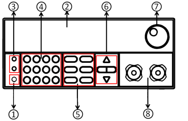
- Power switch
- Vacuum fluorescent display (VFD)
- Compound key and the local switch key
- Number key:
Set the parameters value, achieve the menu’s function by key combination - Function key:
Set the operation mode
Control the input state: On/Off - Direction function
- Rotary knob
- Input terminal
IT8513B+/IT8514B+ IT8514B+/M model
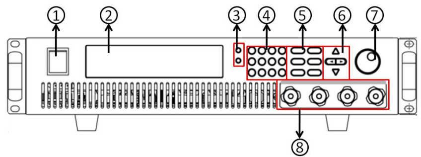
- Power switch
- Vacuum fluorescent display (VFD)
- Compound key and the local switch key
- Number key:
Set the parameters value, achieve the menu’s function by key combination - Function key:
Set the operation mode
Control the input state: On/Off - Direction function
- Rotary knob
- Input terminal
IT8516C+ Model
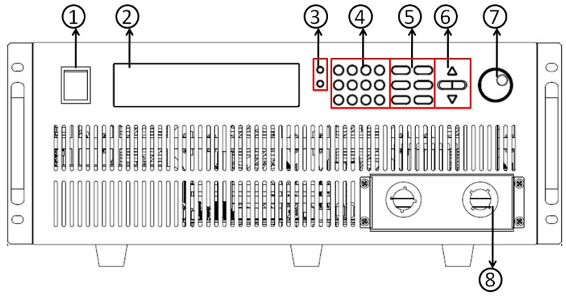
- Power switch
- Vacuum fluorescent display (VFD)
- Compound key and the local switch key
- Number key:
Set the parameters value, achieve the menu’s function by key combination - Function key:
Set the operation mode
Control the input state: On/Off - Direction function
- Rotary knob
- Input terminal
Front Panel Keys
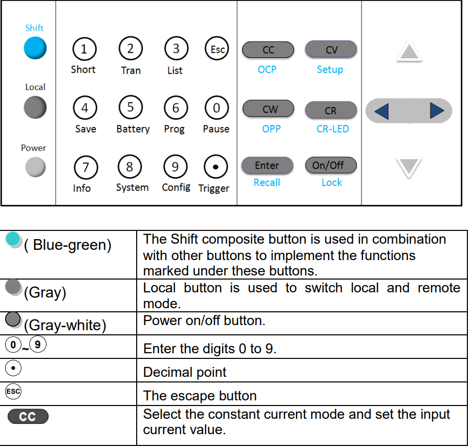
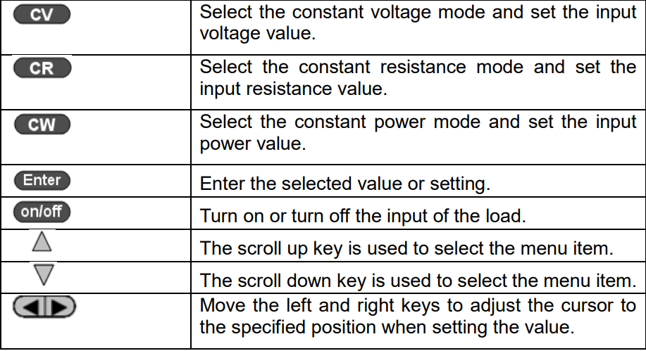
Combination Keys
Press [ button first and then other keys to achieve all kinds of functions in the following table.
[Shift]+[1] (Short) | Start or stopthe short circuittest. |
[Shift]+[2] (Tran) | Set the transient operation parameters. |
[Shift]+[3] (List) | Set the LISToperation parameters. |
[Shift]+[4] (Save) | Store the parameter value of the currently load. Including: voltage, current and power values, and so on. |
[Shift]+[5] (Battery) | Battery test function. |
[Shift]+[6] (Prog) | Automatic test function. |
[Shift]+[7] (Info) | Displays the modelnumber, version number,and serial number of the electronic load. |
[Shift]+[8] (System) | System menu setting |
[Shift]+[9] (Config) | Configure menu setting |
[Shift]+[0] (Pause) | Pressing this button duringthe running of the automatic test indicates that the automatic test is suspended. |
[Shift]+[ ] (Trigger) | Cause an immediate trigger. |
[Shift]+[CC] (OCP) | Enter OCP test function. |
[Shift]+[CV] (Setup) | Set detailed parameters in CC/CV/CW/CR mode. |
[Shift]+[CW] (OPP) | Enter OPP testfunction. |
[Shift]+[CR] (CR-LED) | CR-LED function setting |
[Shift]+[Enter] (Recall) | Recall the load parameter values that have been stored. Includes: voltage, current and power settings, and so on. |
[Shift]+[On/Off] (Lock) | Key lock function |
VFD Annunciators
OFF | The load inputis off. | Error | An error hasoccurred. |
CC | Constantcurrent mode | Trig | Waiting for the trigger signal. |
CV | Constantvoltage mode | Sense | Remote sensingis turned on. |
CR | Constant resistance mode | Prot | Protection function is turned on. |
CW | Constant power mode | Auto | Voltage range automatically seleted function is turned on. |
Rmt | Instrument is in the remote state. | Lock | The keyboard is locked. |
Timer | LOAD ON timer is turned on. | Shift | Shift button has been pressed. |
Rear Panel Introduction
IT8500+ series electronic load different models have different rear panels, the rear panels and keyboards of different models are shown as below.
IT8511+/IT8511A+/IT8511B+/IT8512+/IT8512A+/IT8512B+/IT8512C+/IT8512H+ Model
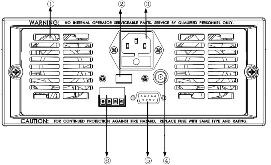
- Thermal window
- Line voltage selection switch 110V/220V
- 3 pin IEC320 AC input connector
- Current monitoring terminal
- 9 Pin serial port interface connector
- 4 pin trigger and remote sensing connector
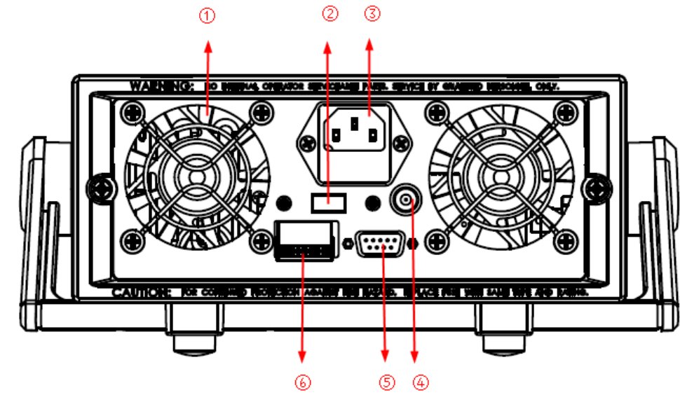
IT8513A+/IT8513C+ Model
- Thermal window
- Line voltage selection switch 110V/220V
- 3 pin IEC320 AC input connector
- Current monitoring terminal
- 9 Pin serial port interface connector
- 4 pin trigger and remote sensing connector
IT8513B+/IT8514B+ IT8514B+/M model
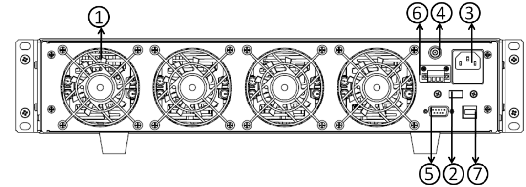
- Thermal window
- Line voltage selection switch 110V/220V
- 3 pin IEC320 AC input connector
- Current monitoring terminal
- RS232 communication cable interface
- 4 pin trigger and remote sensing connector
- USB communication cable interface
IT8516C+ M model
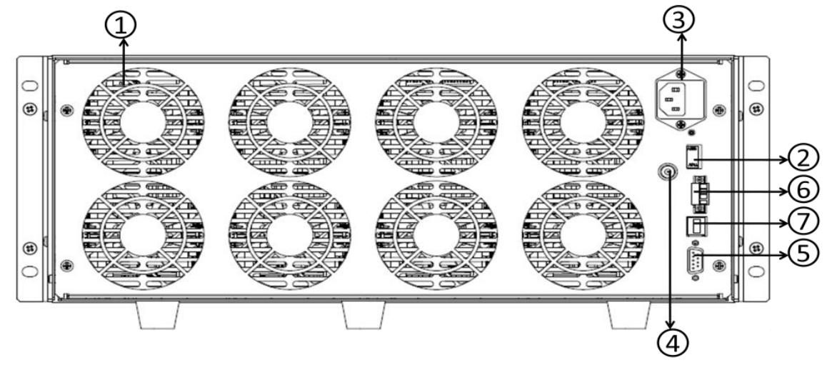
- Thermal window
- Line voltage selection switch 110V/220V
- 3 pin IEC320 AC input connector
- Current monitoring terminal
- RS232 communication cable interface
- 4 pin trigger and remote sensing connector
- USB communication cable interface
Setup Guide
To set up the iTECH DC Programmable Electronic Loads IT8500 plus, follow these steps:
- Unpacking and Inspection: Carefully unpack the unit and inspect for any damage during shipping.
- Power Connection: Connect the device to a suitable power source as per the manufacturer's guidelines.
- Signal Connections: Connect the load terminals to the DC source under test, ensuring proper polarity.
- Communication Setup: Connect the device to a computer or other control systems via USB, RS232, LAN, or GPIB.
- Software Installation: Install the provided software on your computer to configure and operate the load.
- Initial Configuration: Use the software to set up the desired load profile and parameters.
Troubleshooting
If you encounter issues with your iTECH DC Programmable Electronic Loads IT8500 plus, consider the following troubleshooting steps:
- No Display or Power On: Check power connections and ensure that all cables are securely connected.
- Inaccurate Readings: Calibrate the device according to the user manual or contact support for assistance.
- Overheating Issues: Ensure proper ventilation around the device and check for blockages in cooling vents.
- Communication Errors: Verify that communication interfaces are properly connected and configured.
Always refer to the user manual for detailed troubleshooting guides and safety instructions.
Pros & Cons
Pros
- High Precision: Offers accurate load simulations with high resolution.
- Advanced Safety Features: Includes OCP, OVP, and OTP protections for safe operation.
- Scalable Design: Allows for easy expansion by adding more units in parallel.
- Comprehensive Software Support: Facilitates easy configuration and integration into automated test systems.
- Durable Construction: Built with robust materials to withstand heavy use.
Cons
- High Cost: May be expensive for small-scale or budget-conscious users.
- Complex Setup: Requires careful setup and configuration which can be time-consuming.
- Space Requirements: Larger than some other electronic loads due to its modular design.
- Technical Support Dependency: May require technical support for advanced configurations or troubleshooting.
Customer Reviews
Customers have praised the iTECH DC Programmable Electronic Loads IT8500 plus for its reliability and precision in load simulations. Many have noted that while it requires a significant investment, it provides unparalleled performance and flexibility in testing applications. However, some users have reported that the initial setup can be complex and may require additional technical support.
Common complaints include the high cost and the need for a significant amount of space due to its size. Despite these drawbacks, the overall consensus among users is that this device delivers high-quality results and is a valuable addition to any testing lab or engineering facility.
Faqs
What is the maximum power rating of the iTECH DC Programmable Electronic Loads IT8500 plus?
What are the different load modes available on the IT8500 plus?
How do I connect the IT8500 plus to a computer for configuration?
What safety features are included in the IT8500 plus?
Is the IT8500 plus suitable for high-frequency load simulations?
How do I troubleshoot common issues with the IT8500 plus?
Can I expand the capabilities of the IT8500 plus?
What is the typical application of the iTECH DC Programmable Electronic Loads IT8500 plus?
Is technical support available for the IT8500 plus?
What are some common customer complaints about the IT8500 plus?
Leave a Comment
