Itech Digital Control Power Supply Unit IT6721 User Guide
Content
Introduction
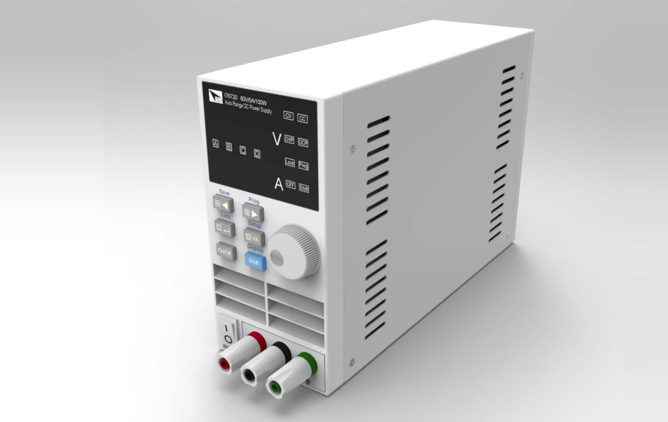
The Itech Digital Control Power Supply Unit IT6721 is a high-performance benchtop power supply designed for a variety of applications. With an adjustable output of 0-60V and a maximum current of 8A, it delivers up to 180W of power, making it suitable for testing and powering electronic devices. Its digital control features ensure precise voltage and current adjustments, while the compact design saves space on your workbench. Priced at approximately $325, it offers excellent functionality for both professionals and hobbyists.
Safety Symbols
 Connect it to safety earth ground using the wire recommended in the user’s manual.
 High voltage danger
 The symbol on an instrument indicates that the user should refer to the operating instructions located in the manual.
About IT6700
With widest voltage and current range, IT6700 digital DC power supplies are applied in many fields.
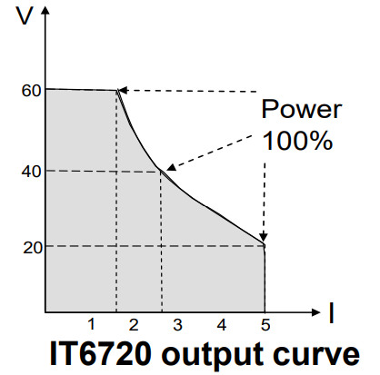
Take IT6720 for example, with max power 100W and output adjustable in 60V/5A, auto control voltage/current slew rate, power rate up to three times rapid than other similar products, a unit can replace three models (60V*1.6A/ 32V*3A/ 20V*5A), reduce your repeat investment.
Example:
When you set the output voltage as 60V, because the max power of IT6720 is 100W, so the max output current is 100W/60V=1.6A. When you change the output voltage to 30V, the output current is 100W/30V=3.2A. Calculate according to the above way when the output voltage is 20V, the output current should be 5A, but as the max rating current of IT6720 is 8A, so the final max output current is 5A.
Function
- Fully digital control
- High resolution 10mV/1mA in Full range
- Low ripple and noise
- Software calibration
- Bright and easy to read display (VFD)
- Constant current and constant voltage output
- Selectable remote control keypads
- High reliability OVP/OCP/OTP protection
- Output on/off control
- Best performance /price ratio
- Storage for 4*100 preset voltage and current output
Specifications
Output Rating | Voltage | IT6720 | IT6721 |
Current | 0~5A | 0~8A | |
Power | 100W | 180W | |
Load Regulation | Voltage | <0.01%+3mV | <0.01%+5mV |
Current | <0.01%+3mA | <0.01%+5mA | |
Line Regulation | Voltage | <0.01%+3mV | <0.01%+5mV |
Current | <0.1%+3mA | <0.1%+5mA | |
| Programming Accuracy | Voltage | <0.05%+10mV | <0.05%+10mV |
Current | <0.2%+2mA | <0.3%+5mA | |
Read back Accuracy | Voltage | <0.05%+10mV | <0.05%+10mV |
Current | <0.1%+2mA | <0.3%+5mA | |
Ripple | Voltage | <2.0mV rms | <5.0mV rms |
Current | <5mA rms | <8mA rms | |
Maximum input apparent power | 300VA | 700VA | |
Dimension | W*H*D | 88*175*282(mm) | 88*175*282(mm) |
Weight | Net | <2.5Kg | <3.5Kg |
Description
The IT6721 features a sleek and durable enclosure designed to withstand the rigors of industrial environments. The front panel includes a high-resolution LCD display that provides real-time monitoring of output voltage, current, and other parameters. The unit is cooled by a silent fan, ensuring quiet operation even under high load conditions.
The power supply is built with high-quality components to ensure reliability and longevity. It supports a wide range of applications, from benchtop testing to integration into complex systems. The digital control system allows for precise adjustment of output parameters, making it versatile for various use cases.
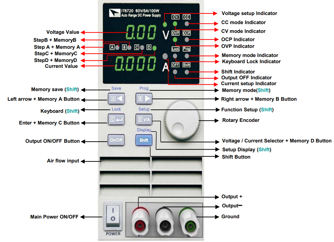
Itech Digital Control Power Supply Unit IT6721 Panel Layout
Quick Start Check out
Confirm whether the power supply has been destroyed in transportation, if there is any flaw, please contact the vender.
Confirm whether the AC input voltage of IT6700 comply with the standards of your country or region.
Note: If switching input voltage, operate through the back panel switch (110V/220V).
After the check of the above matters, power on by press![]()
Setting the voltage
- Press
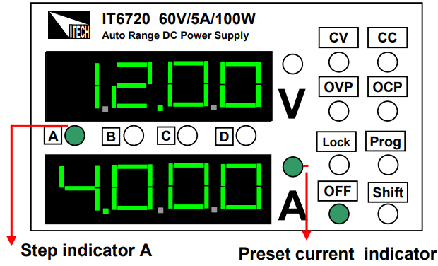
 to light up the voltage setup indicator B. It means IT6700 is in voltage set mode, shown as fig 1.
 - Press
 light up the voltage setup indicator . Now the voltage will rise/decline 1V once you rotary the knob
 . Set the voltage to 12V.

Setting the current
- Press
 to light up the current setup indicator A. IT6700 is in current set mode, shown as fig 1.
 - Press
 to adjust the setup indicator to . Now the current will rise/decline 1V once you rotary the knob
 . Set the current to 4A.
Enable output
- Press
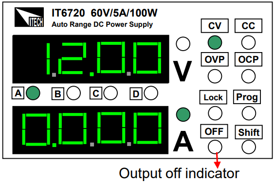
 to enable the IT6700 output. Voltage and current settings will be wink for three seconds,and after that , the display value of numerical display will change from the set value to actual measured voltage and current value.
 - Power off lights will be turned off which means the power is in output state. Press
 again, you will shut power supply’s output
Step value for Cursor Position
Cursor position | Step voltage | Step current |
A | ------ | 1A |
B | 1V | 0.1A |
C | 0.1V | 0.01A |
D | 0.01V | 0.001A |
Check the set voltage and current value
The power supply usually displays the actual voltage and current values. When you want to check the preset voltage and current values, the unit will display automatically settings, press twice, the settings will be displayed for three seconds.
Key lock function
This function can prevent error operation by unauthorized person. Press![]() , after the was lit on, press
, after the was lit on, press![]() , will be lit on, press
, will be lit on, press ![]() (lock)
(lock)![]() will be lit on,which means all keys on the panel except
will be lit on,which means all keys on the panel except ![]() and
and  . Repeat the above operation, key lock function will be disabled.
OVP function
Press![]() , and press
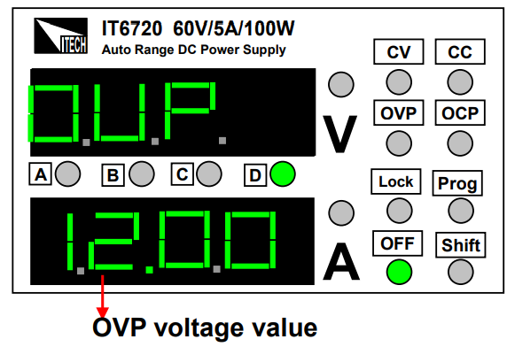
, and press![]() for three seconds, now the panel displays OVP, shown as fig 4. Use
for three seconds, now the panel displays OVP, shown as fig 4. Use![]() and
and ![]() to set OVP value.
to set OVP value.
OCP function
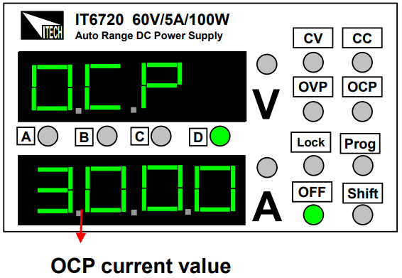
Press![]() to enter into OCP setting interface after setting OVP value, use
to enter into OCP setting interface after setting OVP value, use![]() and
and![]() to set the OCP value
to set the OCP value
Key sound (BEEP)
Press![]() to enter the BEEP setting Interface after finished the OCP setting, select the ON/OFF state with the knob
to enter the BEEP setting Interface after finished the OCP setting, select the ON/OFF state with the knob![]() . ON indicates there is key sound, OFF means no.
. ON indicates there is key sound, OFF means no.
_itech_digital_control_power_supply_unit_it6721.png)
Power address (ADD)
Press![]() to enter the ADD setting interface after finishing the BEEP setting, select
to enter the ADD setting interface after finishing the BEEP setting, select ![]() the and
the and ![]() to enter store address setting. ADD range: 0~30, press
to enter store address setting. ADD range: 0~30, press![]() to confirm。
to confirm。
_itech_digital_control_power_supply_unit_it6721.png)
Store group setting (GRP)
- Press
 to enter into GRP interface after setting the OCP value, use
 and
and  to select store group.
 - IT6700 allows customers to store 100 groups with A/B/C/D four set value for every group.
- Press
 to confirm the chosen group and end the setup mode.
_itech_digital_control_power_supply_unit_it6721.png)
Store operation
In the normal working mode, set the voltage/current value to be stored. Press ![]() and
and![]() , now the Cursor A,B,C,D will wink together. Pressany key
, now the Cursor A,B,C,D will wink together. Pressany key ![]() in to save it.
in to save it.
Recall operation
Press![]() and
and![]() , the indicator PROG will be lit on, which means that IT6720working in the shortcuts mode. Press any key in
, the indicator PROG will be lit on, which means that IT6720working in the shortcuts mode. Press any key in![]() , recall the preset voltage/current value which has been stored.
, recall the preset voltage/current value which has been stored.
When the power supply is on recall operation, that means all you can recall the parameters from the store group. Press any key of to recall ![]() the stored parameter.
the stored parameter.
When the power supply is on recall operation ![]() are disabled, they only can be used with
are disabled, they only can be used with![]() key. Press
key. Press![]() , and press
, and press![]() to exit recall function.CC
to exit recall function.CC
Faulty disposal
If the outputs is disabled:
- Check whether voltage and current settings are zero, if so, reset voltage and current value.
- Check whether the indicator
 is lit on, if so, press
  to enable the outputs.
 - Check whether the indicators
 are lit on, if so, please reset according to the mentioned OVP/OCP/OCP means.
If the keypad is disabled, check whether the indicator![]() is lit on, if so, unlock the keypads as the above means.
is lit on, if so, unlock the keypads as the above means.
Battery charging protection
WARNING: Pay attention to the positive and negative terminals when connecting the battery. If the battery is connected reversely to the power supply, it will result in damage to the power supply.
When using the power supply to charge the battery, a diode and a fuse must be connected in series with the output as shown in the following figure to protect the circuit . The detailed methodology is shown as follows.
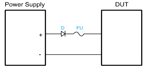
The role of the diode and the fuse in the above figure is described as below.
- The role of the diode is to block any reverse voltage and current flow to the battery to protect the power supply and prevent the internal parts from damage. The series diode can also avoid the condition that the battery discharges due to the internal resistive load of the power supply in the power-off or output-off state.
When selecting the diode, the user should consider the following notes.
The current capacity of the diode should be 110% of the rating current of the battery at least. When setting the input voltage of the battery, the user need to consider the threshold voltage of the diode. The typical threshold voltage of a silicon diode is 0.6 V to 0.7 V. The reverse breakdown voltage of the diode should be more than twice the rating voltage of the battery. The user also need to consider the power of the diode and add a heat sink when necessary
- The role of the fuse is to interrupt the current by melting the metal wire in it when the current rises to a certain value, thereby protecting the circuit.
When selecting the fuse, the user should consider the following notes. The rating current of the fuse should be 150% to 200% of the maximum current of the battery and be less than 150% of the maximum output current of the power supply.
Setup Guide
To set up the itech Digital Control Power Supply Unit IT6721, follow these steps:
- Unpack the unit and ensure all accessories are included (power cord, cables, etc.).
- Mount the unit securely in a well-ventilated area to ensure proper cooling.
- Connect the power cord to a suitable AC power source.
- Turn on the power supply and use the front panel controls or remote interfaces to configure the output settings as needed.
- Connect your load to the output terminals, ensuring all connections are secure and meet safety standards.
Safety Regulations
WARNING
- To avoid electrical shock, do not open the cabinet. Refer servicing to qualified personnel only.
- To avoid injuries, always disconnect power, discharge circuits, and remove external voltage sources before touching components. KEEP AWAY FROM LIVE CIRCUITS.
- We cannot accept responsibility for any direct or indirect financial damage or loss of profit that might occur when using the power supply.
- The instrument chassis and cover must be connected to an electrical ground.
Troubleshooting
Common issues and their solutions include:
- No Output Voltage: Check if the power supply is turned on and if there are any loose connections. Ensure that the output is not set to zero on the control panel.
- Overheating: Ensure good airflow around the unit. If overheating persists, check for dust buildup and clean the unit as necessary.
- Error Messages: Refer to the user manual for specific error codes and their resolutions. Contact customer support if unresolved.
Instructions and Warnings
- Always follow proper safety guidelines when working with electrical equipment.
- Avoid overloading the power supply beyond its rated capacity.
- Regularly inspect cables and connections for damage or wear.
Itech Digital Control Power Supply Unit IT6721 Pros & Cons
Pros
- High precision and stability in power output.
- Advanced digital control system with intuitive interface.
- Robust design suitable for continuous operation in demanding environments.
- Multiple connectivity options for remote control and monitoring.
- High efficiency and silent operation.
Cons
- Higher cost compared to analog power supplies.
- Complex setup may require technical expertise.
- Limited availability upon initial launch.
Customer Reviews
Early reviews from beta testers have been positive, highlighting the unit's reliability and ease of use. However, some users have noted a steep learning curve due to the advanced features and complex interface.
Common Complaints
- Some users find the price prohibitive for smaller-scale applications.
- A few reviewers have mentioned that the manual could be more comprehensive, especially for new users.
Warranty
This hardware product is warranted against defects in material and workmanship for a period of ONE year from date of delivery. IT6700 power supply for use with a hardware product and when properly installed on that hardware product, are warranted not to fail to execute their programming instructions due to defects in material and workmanship for a period of 90 days from date of delivery.
Faqs
What is the maximum output power of the itech?
What are the output voltage and current ranges of the IT6721?
Does the Power Supply Unit have any protection features?
How do I connect my load to the Itech Digital Control Power Supply Unit IT6721?
Can I control the IT6721 remotely?
What should I do if there is no output voltage from the unit?
How often should I clean the unit to prevent overheating?
Is there a comprehensive manual available for setup and operation?
Leave a Comment
