Itechate Programmable AC Power Supply IT7321 User Manual
Content
Introduction
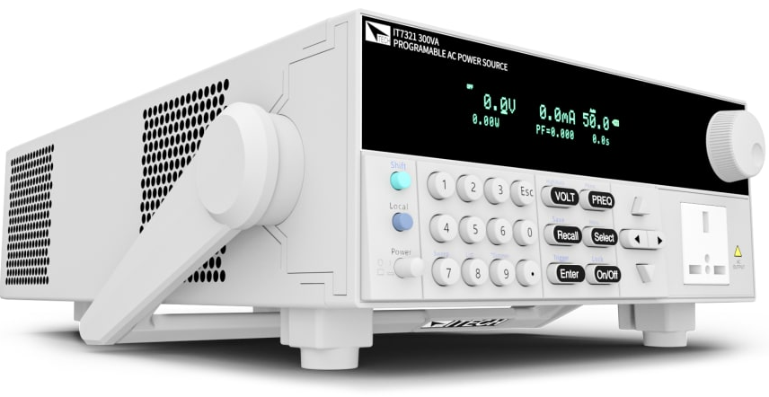
The ITECH Programmable AC Power Supply IT7321 series is a versatile solution designed for various applications in electronics and electrical testing. It offers programmable output with voltage capabilities up to 300 V, current up to 24 A, and power ratings reaching 3000 VA, making it suitable for simulating real-world operating conditions. The cost of the IT7300 series starts at approximately $1,200. Key features include adjustable frequency from 45 Hz to 500 Hz and built-in measurement capabilities, enhancing efficiency in testing environments.
Guarantee
The materials contained in this document are provided “as is”, and is subject to change, without prior notice, in future editions. Further, to the maximum extent permitted by applicable laws, ITECH disclaims all warrants, either express or implied, with regard to this manual and any information contained herein, including but not limited to the implied warranties of merchantability and fitness for a particular purpose.
ITECH shall not be held liable for errors or for incidental or indirect damages in connection with the furnishing, use or application of this document or of any information contained herein. Should ITECH and the user enter into a separate written agreement with warranty terms covering the materials in this document that conflict with these terms, the warranty terms in the separate agreement shall prevail.
Safety Statement
CAUTION
“Caution” signs indicate danger. It is required to pay attention to the contents of these signs during implementation of operations.
The damage to the product or loss of important data may be caused in case of improper operation steps or failure to follow operation steps. Do not continue to implement any improper operation indicated in “Caution” signs when the specified conditions are not fully understood or these conditions are not satisfied.
WARNING
“Warning” indicates danger. It is required to pay attention to the contents of these signs during implementation of operation steps. Personal casualties may be caused in case of improper operation steps or failure to follow these operation steps. Do not continue to implement any improper operation indicated in “Warning” signs when the specified conditions are not fully understood or these conditions are not satisfied.
The power supply is a high-level safety equipment, there is a protected ground terminal. Before Installation or operation, please read the safety signs and instructions in this manual.
Confirm Package Contents
Open the package and check the articles within package box before operation. In case of any non-conformity, missing or appearance wearing, please contact ITECH immediately.
The package box should comprise:
Device name | Quantity | Model | Remarks |
Programmable AC Power Supply |
x1 |
IT7300 series | IT7300 series include: IT7321/IT7322/IT7322H/IT7324/ IT7324H/IT7326/IT7326H/IT7322T/ IT7322HT/IT7324T/IT7324HT/IT73 26T/IT7326HT |
Power Cord | x1 | - | Different types of instruments are equipped with different power cables.For detailed specifications, refer to 1.3 Installation of power cord. |
USB cable | x1 | - | - |
CD | x1 | - | Comprising user manual and documents related to programming and grammatical guidelines. |
Factory alignment report | x1 | - | Test reportbefore delivery |
NOTE
After confirming that package contents are consistent and correct, please appropriately keep package box and related contents. The package requirements should be met when the instrument is returned to factory for repair.
Specification
Model | IT7321 | |
INPUT | ||
Phase | 1 | |
Voltage | 220Vac±10% or 110Vac±10% | |
Frequency | 47-63Hz | |
Max.Current | 6.3A(220Vac) or 10A(110Vac) | |
Power Factor | 0.5(typical) | |
AC OUTPUT | ||
Max.Power | 300VA | |
Max Current(rms) | 0-150V | 3A |
0-300V | 1.5A | |
Max Current(peak) | 0-150V | 9A |
0-300V | 4.5A | |
Phase | 1Φ/2W | |
Total HarmonicDistortion(T.H.D) | ≤0.5% at 45-500Hz (Resistive Load) | |
Crest Factor | 3 | |
Line Regulation | 0.1% max for a ±10%line change | |
Load Regulation | ≤0.5%FS(Resistive Load) | |
Response Time | <100uS | |
SETTING | ||
Voltage | Range | 0-300V High, 150/300V Auto |
Resolution | 0.1V | |
Accuracy | ±(0.2%+0.6V) | |
Temp. coefficient | ±(0.04% per degreefrom 25℃) | |
Frequency | Range | 45-500Hz |
Resolution | 0.1Hz at 45-99.9Hz 1Hz at 100-500Hz | |
Accuracy | 0.1Hz | |
Phase Angle | Range | 0-360° |
Resolution | 0.1° | |
Accuracy | ±1°(45-65Hz) | |
MEASUREMENT | ||
Voltage(rms) | Range | 0-300V |
Resolution | 0.1V | |
Accuracy | ±(0.2%+0.6V) | |
Temp. coefficient | ±(0.04% per degree from 25℃) | |
Current(rms) |
Range | L:120.0mA * |
M:1.200A * | ||
H:3.00A* | ||
Resolution | L:0.1mA | |
M:1mA | ||
H:10mA | ||
Accuracy | L:±(0.2%+0.6mA) | |
M:±(0.2%+6mA) | ||
H:±(0.2%+40mA) | ||
Temp. coefficient | ±(0.04% per degree from 25℃) | |
Current(peak) | Range | 0-12A |
Resolution | 0.01A | |
Accuracy |
±(1%+0.36A) | |
Temp. coefficient | ±(0.05% per degree from 25℃) | |
Power |
Resolution | L:0.01W |
M:0.1W | ||
H:1W | ||
Accuracy | L:±(0.2%+0.2W) (47HZ-65HZ) | |
M:±(0.2%+2W) (47HZ-65HZ) | ||
H:±(0.2%+4W) (47HZ-65HZ) | ||
Temp. coefficient | ±(0.05% per degree from 25℃) | |
GENERAL | ||
Memory | 10 memories | |
Sync Output Signal | Output Signal5V,BNC type | |
Interface(Option) | LAN,USB,RS232 | |
Operation Environment | 0-40℃/20-80%RH | |
Dimension | 1/2 19" 2U | |
Weight | 10Kg | |
Description
The itechate Programmable AC Power Supply IT7321 is engineered to provide high-quality, reliable power for a wide range of applications. Its advanced digital control system ensures precise control over output parameters, allowing users to easily configure and monitor the power supply through an intuitive front panel or remote interfaces.
The device features a compact and rugged design, making it suitable for both benchtop and rack-mount installations. The IT7300 also supports various communication protocols, enabling seamless integration into automated test systems.
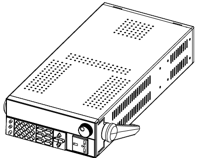
Installation Position
The instrument should be installed at well-ventilated and rational-sized space. Please select appropriate space for installation based on the power supply size
Model IT7321
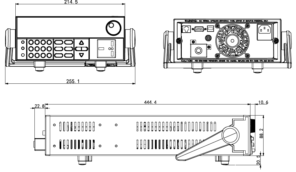
Detailed dimensional drawings
Installation of Power Cord
Connect power cord of standard accessories and ensure that the power supply is under normal power supply.
AC power input level
Working voltage for IT7300 series power supply is shown as follows. So please pay attention to the working input voltage.
- The AC line switch of IT7321 is located at the bottom of the unit.
- The AC line switches of IT7322, IT7322H, IT7324, and IT7324H are located at the rear of the unit. Please pay attention to the AC level setup before provide AC power.
- AC power input level:
- Option 01: 220VAC ± 10%, 47 to 63 Hz
- Option 02: 110VAC ± 10%, 47 to 63 Hz
- IT7326 and IT7326H models support 220V AC input.
- IT7322T, IT7322HT, IT7324T, IT7324HT, IT7326T and IT7326HT models support 380V AC input.
Connecting AC Input
WARNING: The power cords supplied with this product is certified for safety. In case the supplied lines assembly needs to be replaced, or an extension lines must be added, be sure that it can meet the required power ratings of this product. Any misuse voids the warranty of this product.
Before connecting power cords, turn off the power.
IT7321: Connect standard power cord to the power supply input terminal.
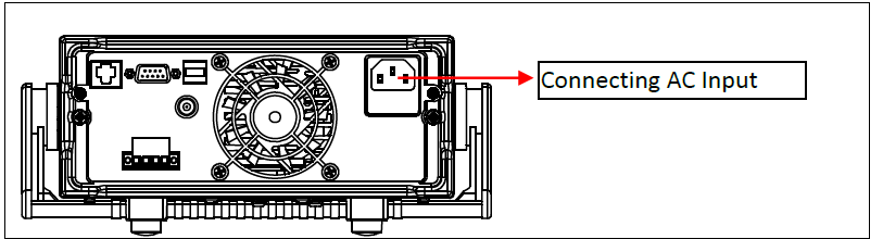
In the above illustration, one end of the AC power cord is connected to the AC input terminal in the rear panel of the power supply.
Connect the wire, zero line and ground to the corresponding terminal of the device. Before inserting, please loose the screw, lock the screw when it is inserted.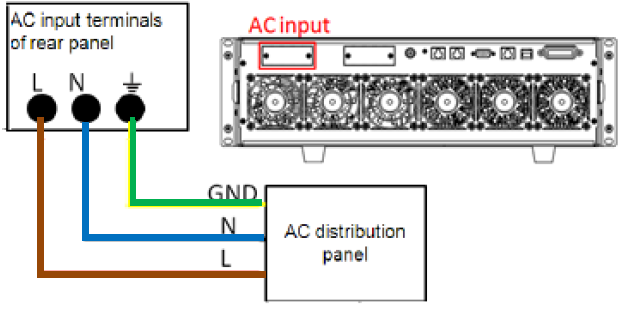
- Connect the three terminals brown to line (L), blue to neutral (N), and yellow-green to ground (GND) on the other end of the power cord to your AC distribution panel.
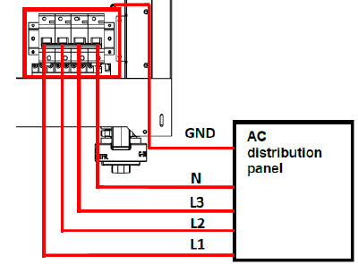
IT7321 AC input connections are the same, and the end of the AC power cord connected to the AC input terminal on the rear panel of the power supply is connected. The user only needs to connect the other end of the AC power cord to the AC distribution panel, the brown terminal is connected to L1, the gray terminal is connected to L2, the black terminal is connected to L3, the blue terminal is connected to N, and the yellow terminal is connected to the GND.
The connection diagram is as follows:
Connecting Test Cables (Optional)
Test cables are not standard accessories of the instrument. Please select optional red and black test cables for individual sales based on the maximum current value. For specifications of test cables and maximum current values, refer to “Specifications of Red and Black Test Lines” in “Appendix”.
WARNING
- Before connecting test cables, be sure to switch off the instrument. Power switch is in Off position. Otherwise, contact with output terminals in rear panel may cause electrical shock.
- To avoid electrical shock, before testing, please make sure the rating values of the testing cables, and do not measure the current that higher than the rating value. All test cables shall be capable of withstanding the maximum short circuit output current of the power supply without causing overheat.
- If several loads are provided, each pair of load wires shall safely withstand the rated short circuit output current of the power supply under full load.
- Always use test cables provided by ITECH to connect the equipment. If test cables from other factories are used, please check that the test cable can withstand maximum current.
The front panel of IT7300 series power supply is equipped with the front panel output terminal and rear panel output terminal (see 2.2 Introduction of front panel and 2.5 Introduction of rear panel).
Before using the output terminal of the rear panel to connect the device under test (DUT), remove the protective cover or panel covering the output terminal on the rear panel firstly, then connect the test cables, and take the other end of the test cables out of the hole in the protective cover or panel, and then put the protective cover or panel back in place. To avoid the risk of electric shock if the output terminal is accidentally touched during the test operation.
Connection of the front panel output terminal
The models that support the front panel output are IT7321.
- The connection method of the front panel output is as follows: directly insert the plug at one end of the cable into the output interface of the front panel, and connect the other end to the DUT.
- The maximum output current of the front panel output terminal is 10A. In order to facilitate operation, the user can directly connect the front panel output terminal if the output current is less than 10A.
- If the output current of the output terminal of the power supply exceeds 10A, the user must connect the rear panel output terminal. If you want to obtain the specifications of the equipment, please refer to 4.1 Specification.
Connection of the rear panel output terminal
The user can connect the rear panel output terminal according to the power output specifications. Specific connection of IT7321 (after removing the protective cover) is shown in the figure below.

- Make sure the power switch of the instrument is off.
- Remove the protective cover or panel that covers the rear panel output terminals.
- Unscrew the screws of the output terminals and connect the red and black test cables to the output terminals. Re-tighten the screws.
- When maximum current that one test cable can withstand fails to meet the current rated current, use several pieces of red and black test cables. For example, the maximum current is 1,200A, then 4 pieces of 360A red and black cables are required.
- Take the other end of the test cables out of the hole in the protective cover or panel and install the cover or panel back.
- Connect the other end of the red and black cables to the DUT terminal.
Setup Guide
To operate the itechate Programmable AC Power Supply IT7321,
- Start by connecting the device to a suitable power source and ensuring all safety precautions are in place.
- Use the front panel controls to set the desired voltage and current levels.
- For remote operation, connect the device via USB, LAN, or GPIB and use the provided software to configure and control the power supply.
- Assemble the unit according to the provided mounting instructions if you plan to use it in a rack-mount configuration.
Remote Control
IT7300 series AC source (except IT7321) has four standard communication interfaces: LAN RS232, USB, and GPIB. IT7321 has a standard communication interface: LAN/USB/RS232. You can choose any one of them to communicate with PC.
RS232 Interface
There is a DB9 connector at the rear of the power supply, when connect to computer, you need to select a cable with COM port on both side; To active you need to press ![]() a button to enable the settings in menu to be the same with the PC communication configuration. You could do the secondary development with all SCPI commands.
a button to enable the settings in menu to be the same with the PC communication configuration. You could do the secondary development with all SCPI commands.
Note
- The RS232 settings must match the settings in front panel system information.
- If any change, please press
 key to modify the menu: SYST SET\COMM.
RS232 data format
RS232 data is a 10-bit word with one start bit and one stop bit. The number of start bit is not programmable. Stop bit is selectable between 1&2.Besides, you can set the parity bit in the menu using the front panel ![]() key. Parity options are stored in a non-volatile memory.
key. Parity options are stored in a non-volatile memory.
Baudrate
The front panel![]() button allows the user to set baud rate which is stored in the non-volatile memory: 4800,9600,19200 38400, 57600,115200
button allows the user to set baud rate which is stored in the non-volatile memory: 4800,9600,19200 38400, 57600,115200
RS-232 connection
Adopt the RS232 cable with DB-9 interface because the serial port of RS232 can be connected with that of the controller (e.g. PC). The modulating cable of the air-conditioner is not recommended. The pins of plug are shown as the following table. If your computer is provided with a RS232 interface with DB-25 plug, a cable and an adapter with DB-25 plug (one end) and DB-9 plug (the other end) are required (not the modulating cable of the air-conditioner)
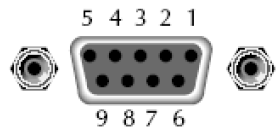
| Pin Number | Description |
|---|---|
| 1 | No connection |
| 2 | TXD, transfer data |
| 3 | RXD, receive data |
| 4 | No connection |
| 5 | GND, ground |
| 6 | No connection |
| 7 | CTS, clear transfer |
| 8 | RTS, ready to transfer |
| 9 | No connection |
RS-232 Troubleshooting
In case of connection failure of RS232, perform following check:
- Check if the computer and power supply are provided with same Baud rate, parity check bit, data bit and flow control. The power supply shall be configured with one start bit (fixed) and one or two stop bits.
- Just as described in the RS232 connector, appropriate interface cable or adapter shall be adopted. Notes: even if the cable is equipped with right plug, internal wiring may be incorrect.
- The interface cable must be connected to the right serial port (COM1 and COM2) of the computer.
Communication Setup
Please ensure the PC and power supply has the same configuration in the following items.
- Baudrate: 9600(4800, 9600, 19200, 38400, 57600, 115200). You could enter the system menu to set the baudrate.
- Data bit: 8
- Stop bit: 1
- Parity bit: (none, even, odd)
- EVEN 8 data bits have even parity
- ODD 8 data bits have odd parity
- NONE 8 data bits have no parity
- Native machine address: (0 ~31, factory default is 0)
- Start Bit
- 8 Data Bits
- Parity=None
- Stop Bit
USB Interface
Use a cable with two USB ports to connect power supply and PC. You can program through USB interface to achieve all functions of power supply.
The functions of USB488 interface are as follows:
- Interface is 488.2 USB488 interface
- Receive the following request: REN_CONTROL, GO_TO_LOCAL, and LOCAL_LOCKOUT
- When the interface receives MsgID = TRIGGER USBTMC command, it will transmit the TRIGGER command to the function layer
The functions of power supply’s USB488 are as follows:
- receive all SCPI commands
- device is SR1 enabled
- device is RL1 enabled
- device is DT1 enabled
LAN Interface
Press![]() the front panel together to access the menu. Select LAN in the Communication from System and then configure Gateway, IP, Mask and SocketPort in the LAN option. Connect the LAN interface of power supply to the computer with a reticle (crossed).
the front panel together to access the menu. Select LAN in the Communication from System and then configure Gateway, IP, Mask and SocketPort in the LAN option. Connect the LAN interface of power supply to the computer with a reticle (crossed).
GPIB Interface
Use a IEEE488 bus to connect GPIB interfaces of power supply and PC. Please ensure that the screws have been screwed down in order to have a full connection. Then press SHIFT + SELECT MENU (Menu) to enter the system menu, and then select the Communication to set the GPIB address. The address range of power supply is 0 to 30. After you set the address, please press ENTER button to confirm, GPIB address is saved in nonvolatile memory.
Specifications of Red and Black Test Lines
ITECH provides you with optional red and black test lines, the user can choose the company's test line for testing. For specifications of ITECH test lines and maximum current values, refer to the table below.
For maximum current of AWG copper wire, refer to table blow.
Note: AWG ( American Wire Gage) it means X wire ( marked on the wire). The table above lists current capacity of single wire at working temperature of 30°C. For reference only.
Troubleshooting
If the device does not turn on,
- Check the power cord and ensure it is properly connected to both the device and the power source.
For output issues,
- Verify that the settings are correctly configured and that there are no short circuits or overloads.
Common problems include incorrect settings,
- Overloaded output, or communication interface issues.
- Always follow safety instructions to avoid electrical shock or damage to the device.
Pros & Cons
Pros:
- High precision and stability in output voltage and current
- Programmable via multiple interfaces for flexible control
- Robust design with multiple protection features
- Compact and versatile for various applications
- User-friendly interface for easy setup and operation
Cons:
- Potentially high cost compared to non-programmable alternatives
- Complex setup may require technical expertise for full utilization
Customer Reviews
Early adopters of the itechate Programmable AC Power Supply IT7321 have praised its reliability and precision. Many users have noted the ease of use and the comprehensive set of features that make it an essential tool in their workflows.
Some common complaints include the high initial cost and the need for technical knowledge to fully leverage its capabilities. However, overall feedback has been positive, highlighting the device's performance and value in professional settings.
Faqs
What is the maximum output power of the itechate Programmable AC Power Supply IT7300?
What are the communication interfaces available on the IT7300?
How accurate is the output voltage of the IT7300?
What safety features does the IT7300 include?
Is the IT7300 suitable for rack-mount installations?
Can I control the IT7300 via software?
What is the estimated price range of the IT7300?
When is the itechate Programmable AC Power Supply IT7300 expected to be launched?
What kind of applications is the IT7300 best suited for?
How do I troubleshoot common issues with the IT7300?
Leave a Comment