Kwikee 372261 Lippert Double Tread Electric RV Steps Instruction Manual
Content
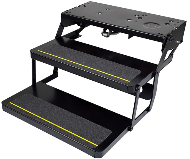
Kwikee 372261 Lippert Double Tread Electric RV Steps
Introducing the Kwikee Lippert Double Tread Electric RV steps are a must-have for any RV owner looking for a reliable, safe, and convenient way to enter and exit their vehicle. These steps offer a sturdy and stable platform, making it easy to get in and out of your RV, even when it is parked on uneven terrain. The double tread design ensures that there is plenty of room for two people to use the steps at the same time, making it perfect for families or couples traveling together. The estimated price for these steps is around $900 to $1,200, and they were launched in the market in 2020.
Detailed Specifications
The Kwikee Lippert Double Tread Electric RV steps come with a range of features that make them stand out from the competition. Here are some of the key specifications:
- Double tread design for added stability and room
- Fully automatic operation with a push-button control
- LED lighting for improved visibility at night
- Weight capacity of up to 600 lbs
- Durable powder-coated finish for long-lasting use
- Motor: 12V DC, 3.5 A
- Dimension: 30.5 x 16 x 7.25 inches
- Step length: 8.5 inches
- Speed: 1.375 inches per second
Safety Information
WARNING The "WARNING" symbol above is a sign that an installation procedure has a safety risk involved and may cause death or serious injury if not performed safely and within the parameters set forth in this manual. Always wear eye protection when performing this installation procedure. Other safety equipment to consider would be hearing protection, gloves, and possibly a full face shield, depending on the nature of the installation procedure.
WARNING The coach MUST be supported per manufacturer's specifications before working underneath. Failure to do so may result in death or serious injury.
CAUTION Moving parts can pinch, crush or cut. Keep clear and use caution.
Motor Assembly Identification
NOTE: This information was obtained from Kwikee manual 1422279 Rev O1 and manual updates dated April 2005 through May 2012. This manual discusses Kwikee electric steps manufactured from January 2005 to the present. Due to various changes in functionality, this manual does not apply and should not be used as a reference to previous versions of Kwikee electric step.
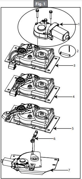
This manual replaces Kwikee Owner's Manual #880 (Kwikee #1422279 dated September 2002) which covered electric step production from January 2002 until January 2005 and Kwikee Owner's Manual #825 (Kwikee #1422257 dated September 1997) which covered electric step production from 1997 until January 2002. To determine correct replacement parts, refer to Figure 1 and the charts in the Replacement Parts section to identify the motor assembly required. Replacement parts for steps equipped with older motor/gearbox are available online.
Product Information
Kwikee steps manufactured prior to 2006 utilized motor, gearbox, linkage, door switch, and controller which may not be directly replaceable with current components. While some direct replacement parts are currently available, it is possible that a complete update kit will be required for repair. The last replacement components made in 2006, and again in 2019. In 2006 the IMGL motor replaced older motor/gearbox units and are referred to as IMGL II. Update Kit motor/gearbox/linkage parts. In 2019 the IMGL motor and controller were updated. The IMGL motor or controller will need to be replaced together. Most steps IMGL components have been revised multiple times, however, the 23 series triple step will continue to use IMGL components.
Mid 1999 and older Kwikee Classic Steps
- Service and Support Discontinued Due To Age of Product. Late 1999-2005 pre IMGL
- Manufactured With Pre-IMGL Components.
- Normally Open (N/O) Door Switch.
- Should Be Upgraded With Appropriate IMGL II Upgrade Kit (A, B, or C Linkage Style) (See Page 5).
- Some Direct Replacement Service Parts Exist, Determined On A Case By Case Basis By Step Series Number and Part Needed (See Page 4). 2006-2018 IMGL
- Steps Manufactured With New Integrated Motor/Gearbox/Linkage (IMGL) Parts.
- Normally Open (N/O) Door Switch.
- If Motor and/or Controller Need Replaced, They Must Be Replaced Together With The New IMGL II Motor and Controller (See Page 5). 2019 and beyond IMGL II
- Steps Manufactured With New IMGL II Components.
- Motor and Controller Are Different Than The IMGL Motor and Controller (See Page 5).
- Normally Open (N/O) Door Switch.
Kwikee Lippert Double Tread Electric RV Replacement Parts
Replacement Parts for Series Steps 22, 28A*, 30, 32, 33, 34, 35, 36, 38 and 40 | ||
Callout | Description | Part Number |
1 | Motor and Screws | |
2 | Cotter Pin and Clevis Pin | |
3 | Gear/Linkage 'A' Curved | |
Replacement Parts for Series Step 23 | ||
Callout | Description | Part Number |
1 | Motor and Screws | |
2 | Cotter Pin and Clevis Pin | |
3 | Gear/Linkage 'A' Curved | |
Replacement Parts Series Steps 28, 31, and 39 | ||
Callout | Description | Part Number |
1 | Motor and Screws | |
2 | Cotter Pin and Clevis Pin | |
4 | Gear/Linkage 'B' Straight | |
Replacement Parts Series Step 26 | ||
Callout | Description | Part Number |
1 | Motor and Screws | |
2 | Cotter Pin and Clevis Pin | |
5 | Gear/Linkage 'C' Straight 1101427 379162 | |
Replacement Part for Series Steps 24 and 25 | ||
Callout | Description | Part Number |
1 | Motor and Screws | |
6 | Link/Assembly 24 / 25 | |
7 | Motor Table 24 / 25 | |
*Motor will vary slightly from motor 676061. Motor 369506 will come with a 9-tooth pinion gear and spring clip to engage with motor table 369529.
Linkage "A" / Series 22, 27, 28A,30, 32, 33,34, 35, 36, 38, 40, 41, Platinum | |||||
Late 1999-2005 | 2006-2018 IMGL | 2019 and Later | |||
*Requires IMGL II Update Kit | *If motor and/or controller fails on IMGL, then both must be replaced with IMGL II motor and controller |
IMGL II Motor only with mounting screws |
IMGL II Controller only |
IMGL II Kit Motor Gearbox/ Linkage | IMGL II Update Kit Motor Gearbox/ Linkage Controller Door Switch 4-Way Pigtail Misc. Hardware |
781008 | 786949 | ||||
Linkage "B" / Series 28,31, 39 | |||||
Late 1999-2005 | 2006-2018 IMGL | 2019 and Later | |||
*Requires IMGL II Update Kit | *If motor and/or controller fails on IMGL, then both must be replaced with IMGL II motor and controller |
IMGL II Motor only with mounting screws |
IMGL II Controller only |
IMGL II Kit Motor Gearbox/ Linkage | IMGL II Update Kit Motor Gearbox/ Linkage Controller Door Switch 4-Way Pigtail Misc. Hardware |
781008 | 786949 | ||||
Linkage "C" / Series 26 | |||||
Late 1999-2005 | 2006-2018 IMGL | 2019 and Later | |||
*Requires IMGL II Update Kit | *If motor and/or controller fails on IMGL, then both must be replaced with IMGL II motor and controller |
IMGL II Motor only with mounting screws |
IMGL II Controller only |
IMGL II Kit Motor Gearbox/ Linkage | IMGL II Update Kit Motor Gearbox/ Linkage Controller Door Switch 4-Way Pigtail Misc. Hardware |
781008 | 786949 | ||||
Linkage "A" / Series 23 | ||||
Late 1999-2005 | 2006 and Later IMGL | |||
*Requires IMGL Update Kit |
IMGL Motor only with mounting screws |
IMGL Controller only |
IMGL Motor Gearbox/ Linkage | IMGL Update Kit Motor Gearbox/Linkage Controller Door Switch 4-Way Pigtail Misc. Hardware |
Step Frame Replacement Chart | ||
Description | Frame Only | Complete Step |
Step Series number 22 | * | |
Step Series number 23 | * | |
Step Series number 24 | * | |
Step Series number 25 | * | 369552 (7" rise) |
3658373 (8" rise) | ||
Step Series number 26 | ||
Step Series number 27 | ||
Step Series number 28 | ||
Step Series number 28A | ||
Step Series number 30 | ||
Step Series number 31 | Obsolete | Obsolete |
Step Series number 32 | ||
Step Series number 33 | * | |
Step Series number 34 | ||
Step Series number 35 | ||
Step Series number 36 | * | |
Step Series number 38 | * | |
Step Series number 39 | ||
Step Series number 40 | ||
Step Series number 41 | * | |
Step Series Platinum | ||
Step Light | ||
* Frame only not available for this series. Order complete step.
Steps With Control Unit
This manual has been provided to assist you with the identification, operation, maintenance, and troubleshooting of the Kwikee Electric Step equipped for use with a step lockout switch, control unit and permanent magnet motor. This manual does not apply and should not be used as a reference to previous versions of a Kwikee Electric Step.
The control unit is essentially a current sensor as well as a switching device. When the motor assembly moves the step tread to its extended position, or stops moving because of an obstruction such as a curb or the binding of a damaged or bent step frame, the motor draws a larger amount of current. The control unit senses the larger current draw and shuts off the power to the motor.
All control units are equipped with an ignition override system. This system is designed so that the vehicle will not be driven with the step in the extended position. When the step is locked in the extended position, the door closed, and the ignition is turned on, the ignition override system will engage and the step will automatically retract.
Note: Refer to vehicle OEM owner’s manual (or OEM Requirements) which will provide switch position of “on” or “off” for the step lock position.
The "Auto Extend" feature is another safety feature designed to extend the step when the door is opened for the first time after the vehicle ignition is turned off, regardless of the position of the step switch. Some van steps use door-switch-only operation. When the door is opened the step extends and the step retracts when the door is closed.
Steps Without Control Unit
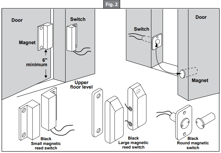
This manual has been provided to assist you with the identification, operation, maintenance, and troubleshooting of the Kwikee Electric Step equipped with a self-centering rocker switch (Fig. 2). This manual does not apply and should not be used as a reference to previous versions of a Kwikee Electric Step.
Note: Follow the instructions in this manual carefully. Failure to do so may result in damage to the step control, the motor and/or the vehicle wiring. Such damage may also result in voiding the warranty.
General Service Notes
Failure to act in accordance with the following may result in death or serious personal injury. Read all operating instructions first before using your Kwikee® Electric Step.
Description
The Kwikee Lippert Double Tread Electric RV steps offer a safe and convenient way to enter and exit your RV. With their double tread design, these steps provide plenty of room for two people to use them at the same time, making them perfect for families or couples traveling together. The fully automatic operation means that you can easily extend and retract the steps with the push of a button, and the LED lighting ensures that you can see where you're stepping at night. The steps are made from durable materials and come with a powder-coated finish that ensures long-lasting use. With a weight capacity of up to 600 lbs, these steps are suitable for even the heaviest RVs.
Prior To Operation
If the power wire to the step is disconnected from its source and reconnected, a spark is common. This is caused by the momentary charging of the control unit and does not necessarily indicate the system is staying on, which would cause a drain on the battery.
To determine if a control unit is not shutting off, remove the 4-way connector to the chassis and the 2-way connector between the step motor and the control unit. Place a voltmeter between the red and yellow motor wires at the 2-way connector from the control unit. Reconnect the 4-way connector. Place the step switch in the appropriate position for the step to remain in the extended position. If any voltage registers on the meter for more than five seconds, the control unit is not shutting off and may be defective. When doing this test, switch the voltmeter leads back and forth between the red and yellow motor wires to make sure no voltage registers.
If any voltage registers for more than five seconds, disconnect the 4-way connector to keep the step motor from overheating. If zero voltage is present, the control unit has shut off and is normal. If the step does not work or operates erratically (for example, extends part way and shuts off) the first item to check is the vehicle battery. Low supply voltage may cause erratic operation of the step. Poor ground connections may also cause erratic operation of the step. Check battery voltage and condition. A battery in good condition and properly charged will have a no-load voltage or approximately 12.6 volts. Check the voltage at the battery and at the 4-way connector by the control unit. Make sure all battery and step control unit connections are clean and secure. Recharge or replace the battery as necessary and retest the step for proper operation.
The step may also operate erratically if it is operating directly from a converter and the converter output is not adequate or properly filtered for clean DC voltage. The converter MUST be capable of producing a minimum of 30 amps for proper step operation.
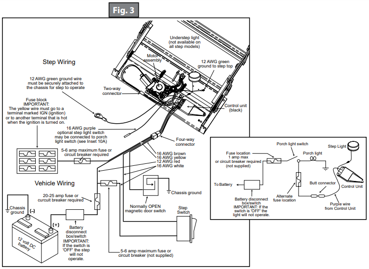
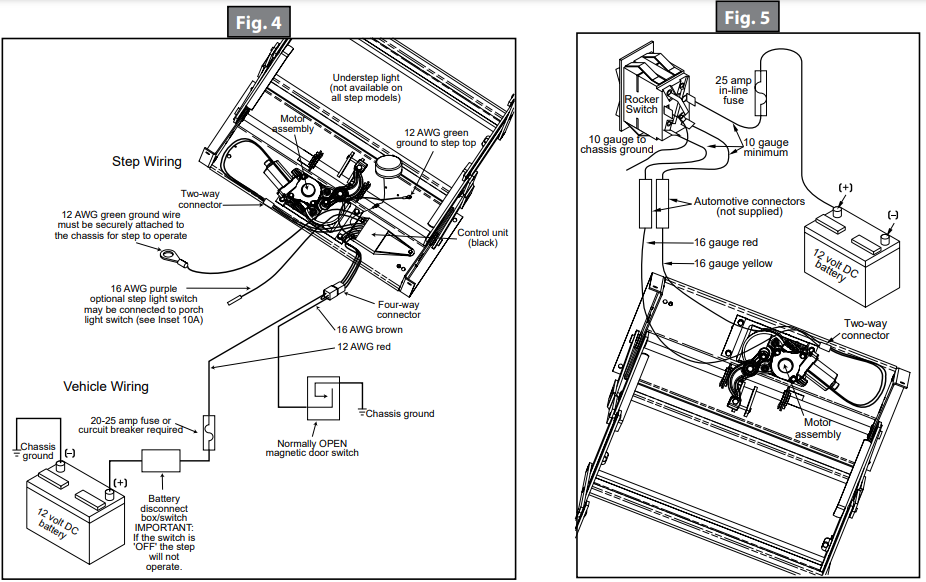
The step will not function if the ground to the control unit is lost between the step control unit and the vehicle chassis (the long green ground wire) or between the vehicle battery and the ground (negative battery cable). Make sure the battery terminals and all wire connections are clean and tight. Verify that all wires meet the minimum requirements (Fig. 3, Fig. 4 and Fig. 5).
Operation
If the vehicle is driven with the step in the extended position, there is the possibility of causing major damage to both the step and the coach. Always be sure that the step is fully retracted before traveling. If the step is left extended and strikes an obstruction while the vehicle is moving, major damage to both the step and the vehicle could result.
Step safely supports up to 300 lbs. DO NOT OVERLOAD THE STEP ASSEMBLY. Do not hold the switch in for longer than it takes to either extend or retract the step or damage to the motor will result.
Note: If the yellow wire from the 4-way connector is not connected to an ignition power source, the ignition safety system will be inoperative and the step will remain in the extended position. In this case, the override switch MUST be turned off for the step to retract.
Note: If the yellow wire from the 4-way connector is not connected to an ignition power source, the step will not retract with the step in the override "on" position when the door is closed and the ignition is on.
Step With Control Unit (Normal/Auto Mode)
- After the installation is complete and with the entrance door open, place the step switch in the position for the step to extend when the door is opened and retracted when the door is closed (step assembly follows the door).
- Close the door. The step should retract and lock in the UP position.
- Open the door. The step should extend and lock in the DOWN position with the under step light illuminated.
- The under step light operation is as follows:
- A. The light is on when the step is extended.
- B. The light is off when the step is retracted.
- C. In the event the coach door/screen door is left open, the light will turn off after five minutes.
- D. The under step light is not available on all step models.
Step With Control Unit (Lock/Stationary Extended Mode)
- If your step is equipped with a step switch, and you would like the step to remain in the extended position while the door is opened and closed, place the step switch in the position for the step to extend when the door is opened and retracted when the door is closed (step assembly follows the door). The step should remain in the extended position with the under step light off when the door is closed.
- With the step switch in the appropriate step lock position, the step extended, and the entrance door closed, turn the vehicle ignition on. The ignition override system will go into effect and the step will automatically retract. Note: If the yellow wire from the 4-way connector is not connected to an ignition power source, the ignition safety system will be inoperative and the step will remain in the extended position. In this case, the step lock switch must be placed in the Automatic Mode position for the step to retract.
- Turn the vehicle ignition off and open the door. The step will extend and lock in the DOWN position. This is the "Auto Extend" feature. When the vehicle ignition is turned on, the step will always activate with the door movement, regardless of the step switch position. Note: If the yellow wire from the 4-way connector is not connected to an ignition power source, the ignition will not cause the step to retract if the step lock switch is placed in the Automatic Mode position, regardless of the door position.
Step Without Control Unit
- To extend the step, push and hold the bottom half of the rocker switch. Make sure the step is completely extended and locked in position before releasing the switch.
- Push and hold the top of the rocker switch to retract the step. Make sure the step is completely retracted and locked in position before releasing the switch.
Note: The extend/retract function will be reversed if the red and yellow terminal connections are reversed or the step is equipped with a reverse-driven motor assembly (such as on the 37 and 42 Series Steps).
Replacement Parts— All StepSeries | |||
Part |
Description |
Part Number |
Part Number |
Door Switches | Magnetic, small rectangular | 379404 | |
3/4" core round | 379405 | ||
Magnetic,large rectangular | 378043 | ||
Magnetic, 3/8" core round | 379393 | 378385 | |
Plated plunger switch | |||
Control | Control with step lockout | ||
Rocker Style Power Switch | For allfully automatic steps | ||
Self-Center Rocker Switch | Steps NOT equipped with control unit | ||
*Indicates a WHITE switchwith a NORMALLY CLOSED status. | |||
**For Step Series 23, Part Number is 379146 | |||
Troubleshooting and Test Procedures
The Step Test Procedures are provided to troubleshoot and test all Kwikee® Electric Step functions. The procedures are designed to initially check the basic functions of the step separately from the RV wiring to determine whether or not the step is malfunctioning. The procedures test various components of the step until the source of the malfunction is located. Using the procedures will shorten and reduce the time spent troubleshooting.
Read the entire procedure prior to testing.
Some portions of the test procedures require additional equipment. This equipment includes:
- Voltmeter
- Well-Charged 12V DC Automotive Battery
- 4-Way Connector/Pigtail Part Number 369243
Testing The Step Assembly
- Inspect the step for visible damage that might restrict step operation.
- Obtain a 4-way pigtail connector Part Number 369243.
Disconnect 4-way connector on underside of step and connect the step-half of the connector to the 4-way connector pigtail (Fig. 3, Fig. 4 and Fig. 5).
- Set a fully charged 12 volts DC automotive battery beside the step.
Note: Do not allow the battery terminals to come in contact with the step. Complete a ground for the step tests by connecting a 10 AWG wire from the negative battery terminal to the green ground wire of the control unit. - To supply power, attach the red wire from the pigtail to the positive battery terminal. The step will extend.
- With the power and ground connections complete, all functions of the control unit can be checked at the four wires of the pigtail. The brown wire is the door switch, the white wire is the step lockout switch, and the yellow wire is the ignition override.
- To retract the step, touch the brown wire to the negative battery terminal.
- To extend the step, remove the brown wire from the negative battery terminal.
- To test the ignition override feature, extend the step. With the step extended, connect the white wire to the positive battery terminal and attach the brown wire to the negative battery terminal. Next, touch the yellow wire to the positive battery terminal. The step should retract. Remove the brown wire and the step should extend.
- If any of the step functions do not work, the source of the malfunction is either in the control unit and/or the motor. Proceed to the “Testing the Motor” section. If all of the step functions do work, the malfunction is either in the door switch, step lockout switch, or the vehicle wiring. Proceed to “Testing the 4-way Connector” section. To test the “Auto Extend” feature:
- Touch the brown wire to the negative battery terminal to retract the step.
- While holding the brown wire to the negative battery terminal, remove the yellow wire from the positive battery terminal.
- Touch the white wire to the positive battery terminal. The step will stay retracted.
- Now, remove the brown wire and the step should extend.
- Next touch the brown wire to the negative battery terminal. The step should stay extended.
Van Steps
If the van step is equipped with a splash cover, remove the cover to access motor assembly and control unit. If step is locked in retracted (UP) position and the plastic cover cannot be removed, disassemble the step tread to access the plastic cover. To disassemble the tread, remove the eight 1/4" - 20 x 1” long hex head bolts in tread side rails (connects tread and sliding blocks to side rail). This allows the tread to drop out of the way and the plastic cover to be accessible. Reassemble the tread after removing the cover. Reinstall the cover after testing procedures and any necessary repairs are complete. Fully extend the step to reinstall the cover. Make sure that the 4-way connector exits the notch in the plastic cover when reassembling.
Warning: Step control wiring is only to be used for step and step light (provided with the step) functions. Do not splice or tap into any of the step wiring. Failure to heed this warning may result in failure of step control, which may result in loss of step function or fire in the step control.
Testing The Motor
If the step extends and retracts during this test, the condition of the step motor is good.
- Disconnect the 2-way connector between the step motor and the control unit.
- Connect the motor’s red wire to the positive battery terminal of the battery and touch the motor’s yellow wire to the negative battery terminal of the battery to extend the step.
- To retract the step, reverse the connections.
Note: On steps with reverse polarity plug Part Number 365884, reverse the red and yellow wire connections to perform the previous test.
Testing The 4-Way Connector
Note: The step wiring circuit must be independent. No other device (i.e. alarm systems, step well lights, etc.) can be connected to the step wiring circuit. Any device connected to the steps wiring can cause the step to malfunction and will void the warranty.
To check the main power source, connect a voltmeter between the red wire from the 4-way connector (vehicle half) and the ground terminal at the end of the control unit’s green ground wire (Fig. 6). The reading should be a minimum of 12 volts DC.
A. If the voltage reading is low, there may be a loose or corroded connection at the battery, a low charge level on the battery itself, or a poor ground.
B. If the voltage reading is zero volts, check the step fuse/circuit breaker, all connections, and the condition of the wiring between the battery and the plug, including the ground connection at the chassis.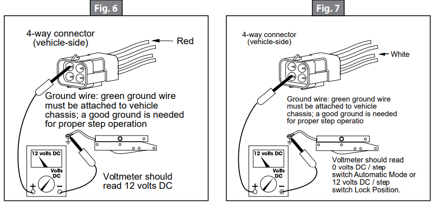
To check the step switch, connect a voltmeter between the white wire from the 4-way connector (vehicle half) and the terminal at the end of the control unit’s green ground wire (Fig. 7). The reading should be a minimum of 12 volts DC with the switch in one position, and zero volts DC with the switch in opposite position.
Note: Refer to vehicle OEM owner’s manual (or OEM Requirements) which will provide the switch position of “on” or “off” for the step lock position.
A. If the voltmeter reads 12 volts DC when the step switch is in the Automatic Mode position, there is a problem in the step switch circuit.
B. Check the 6 amp in-line fuse, the step switch itself, and the condition of the circuit’s wiring and terminal connections.To check the door switch, connect a voltmeter between the red wire from the 4-way connector (vehicle half) and the brown in the same connector (Fig. 8). The voltage should be a minimum of 12 volts DC when the door is closed and zero volts when the door is open. A. If the readings are incorrect, there is a problem with the switch.
B. Check the door switch and the condition of the circuit’s wiring and terminal connections.To check the ignition override system, connect a voltmeter between the yellow wire from the 4-way connector (vehicle half) and the ground terminal on the end of the control unit’s green ground wire (Fig. 9).
A. The voltage reading should be approximately 12 volts DC when the ignition is on and zero volts when ignition is off.
B. If the reading is zero volts when the ignition is on, check all terminal connections, wiring, and the vehicle’s ignition fuse.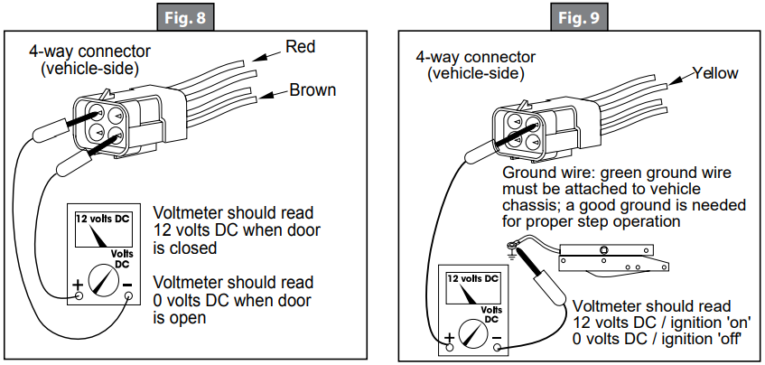
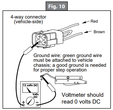
For steps equipped with door switch only operation:
A. Connect the white jumper wire from the vehicle half of the 4-way connector and the ground terminal at the end of the control unit’s green ground wire (Fig. 10).
B. Be sure to use the terminal with only the white wire.
C. The reading should be 12 volts DC. If the voltage reading is more, the white wire is connected to 12 volts and should be cut.
Setup Guide
Setting up the Kwikee Lippert Double Tread Electric RV steps is relatively straightforward. Here are the steps to follow:
- Extend the steps to the ground by pressing the "EXT" button on the control panel.
- Connect the power supply to the RV's electrical system.
- Check that the steps are level and stable before use.
- Retract the steps by pressing the "RETR" button on the control panel.
Maintenance
Step Assembly Lubrication
Clean all mud, salt, and road grime from the step before lubricating. Lubricate all moving parts (bearings, pivot points, slides, clevis pin, and drive linkage ball) every 30 days with a good quality moisture and heat resistant penetrating grease. KwikLube Spray Grease is specially formulated to lubricate Kwikee Electric Steps and is recommended for lubricating all moving parts. See figures 11-17 for lubrication locations.
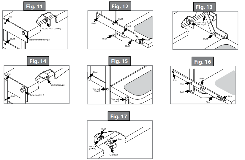
Note: Silicone lubricants and WD-40 are not recommended for use. They have a tendency to evaporate and dry the mating surfaces which leave them vulnerable to the elements.
Note: Figures 11-17 are to be used for general reference purposes only. Some may not pertain to your particular step model.
- For square shaft bearings, lubricate around outside and under head of bearings (Fig. 11 and Fig. 13).
- On step models equipped with a plastic cover, this cover will have to be removed to lubricate center bearings (Fig. 14). Lubricate bearings under cover every 90 days (Fig. 14).
- Lubricate around the bushing-in-bushings (Fig. 14).
- Maintain clean, dry electrical connections at the 2-way and 4-way connectors and any butt connections leading from the 4-way connector to the vehicle. A small dab of dielectric grease at the connections and replacing corroded butt connections with heat shrink type crimp style automotive connectors will help maintain a good electrical source for the step.
Warning: If the cam stops are not properly adjusted the step may not extend fully to the locked-out position. Using a step with loose or out-of-adjustment cam stops may cause damage to the motor assembly and/or the drive linkage.
Note: The adjustment of cam stops applies to 24, 25, 27, 32, 34, 35, 36, 38, and 40 Series Steps.
Kwikee Steps are fitted with adjustable cam stops on the step frame that help lock the step in the "out" position, creating a firm stepping platform and relieving load-bearing stress on the motor and drive linkage. The cam is adjusted at the factory, but due to the rigors of shipping, installation, and normal use the cam may fall out of adjustment and need to be tightened. When the cam stops are out of adjustment, the step may feel loose or "mushy" when stepped on. The cam stops are located under the step top on the 32, 36, and 38 Series Steps, and on the bottom tread side rail on the 24, 25, 27 and 40 Series Steps. There is one stop on each side of the step.
Caution: When working under the step, be sure that the step cannot be activated and that nothing can get caught in the step mechanism.
- Loosen the stops so they move freely and retract the step.
- Extend the step fully to its locked extended position (Fig. 18). Make sure that the motor assembly linkage rests against the gear case (Fig. 18). Repeat if needed until the motor assembly locks in the extended position.
Push the stops against the leg and tighten securely (Fig. 19). Make sure that both stops are tightened and that they rest securely against the leg.
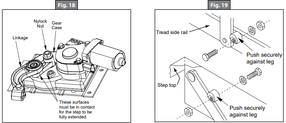
- Retract and fully extend the step. Check the motor assembly to make sure that it is locked all the way out, and that both stops are secure against the legs. Repeat steps 3 and 4 if needed to properly adjust the stops.
- Push on the front edge of the step tread. If the step seems loose, repeat steps 2-4. The stops may not be properly adjusted so that they rest tightly against the leg.
Troubleshooting
Here are some common problems and solutions that you may encounter with the Kwikee Lippert Double Tread Electric RV steps:
- Problem: The steps are not extending or retracting fully.
Solution: Check that the power supply is connected correctly and that the control panel is functioning properly. If the problem persists, contact Kwikee Lippert for further assistance. - Problem: The steps are not level and stable.
Solution: Solution: Adjust the leveling jacks to ensure that the RV is level. If the steps still do not feel stable, contact Kwikee Lippert for further assistance.
Pros & Cons
Pros
- Double tread design provides plenty of room for two people to use the steps at the same time
- Fully automatic operation with push-button control
- LED lighting for improved visibility at night
- Durable powder-coated finish for long-lasting use
- Weight capacity of up to 600 lbs
Cons
- Expensive compared to manual steps
- Requires a power supply to operate
- May require adjustment to level and stabilize
Customer Reviews about Kwikee 372261 Lippert Double Tread Electric RV
Customers who have purchased the Kwikee Lippert Double Tread Electric RV steps have praised their convenience and durability. Many have noted how easy they are to use and how stable they feel compared to manual steps. However, some have noted that the steps can be expensive and may require adjustment to level and stabilize. Overall, customers have reported that these steps are a worthwhile investment for any RV owner looking for a reliable and safe way to enter and exit their vehicle.
Faqs
What is the Kwikee 372261 Lippert Double Tread Electric RV Steps?
How do I install the Kwikee 372261 Lippert Double Tread Electric RV Steps?
How does the automatic retraction feature work Kwikee 372261 Lippert Double Tread Electric RV Steps?
What safety features are included in the Kwikee 372261 Lippert Double Tread Electric RV Steps?
How often should I lubricate the Kwikee 372261 Lippert Double Tread Electric RV mechanism?
What is the estimated price for the Kwikee 372261 Lippert Double Tread Electric RV Steps?
What maintenance is required for the Kwikee 372261 Lippert Double Tread Electric RV Steps?
Is the Kwikee 372261 Lippert Double Tread Electric RV Steps step compatible with all RV models?
How do I troubleshoot if the Kwikee 372261 Lippert Double Tread Electric RV Steps is not extending or retracting properly?
Is the Kwikee 372261 Lippert Double Tread Electric RV Steps waterproof?
Leave a Comment