Lippert LCI 236575 RV In-Wall Slide-Out Motor Owners Manual
Content
Introduction
Lippert LCI 236575 RV In-Wall Slide-Out Motor is a robust and efficient component designed to power the slide-out mechanism in RVs, ensuring smooth and reliable extension and retraction of the slide-out room. Engineered for compatibility with Lippert's In-Wall Slide-Out systems, this motor offers durability and consistent performance, making it an essential part of maintaining and enhancing the functionality of your RV's slide-out feature.
IN-WALL SLIDE-OUT COMPONENTS
Callout | Part # | Description |
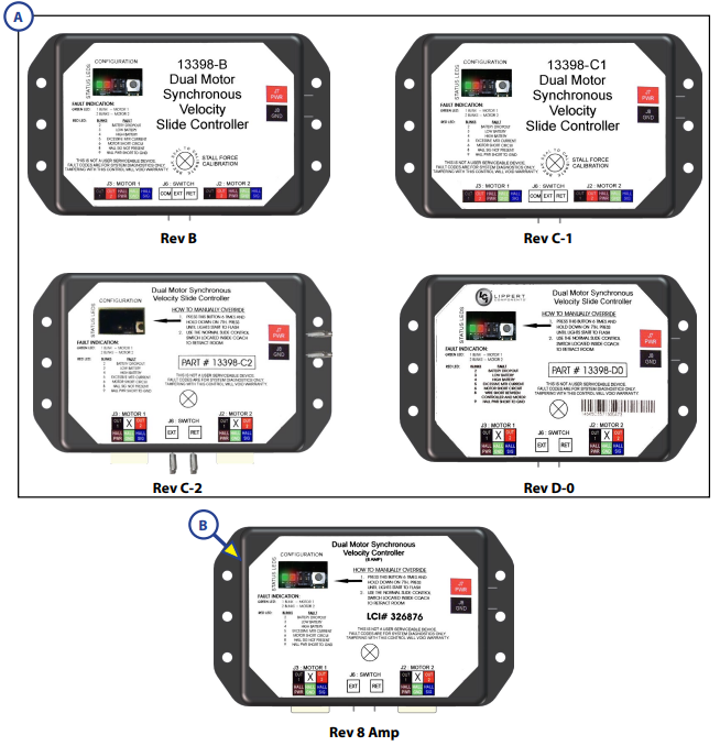
A | 211852 | Dual Motor Synchronous Velocity Slide Controller |
B | 326876 | Dual Motor Synchronous Velocity Slide Controller NOTe: This controller will not replace other controller versions. |
Callout | Part # | Description |
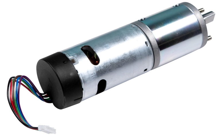
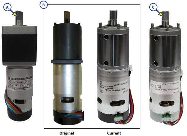
A | 229466 | Motor, 300:1 (Cannot be substituted for Callout B; 236575) |
B | Motor, 300:1(Original, No Longer Available) | |
Motor, 300:1 (Current) | ||
C | 287298 | Motor, High Torque 500:1 |
Callout | Part # | Description |
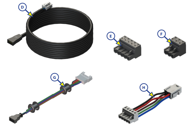
D | 238744 | 5 ft. Controller to Motor Harness |
| 238990 | 10 ft. Controller to Motor Harness | |
| 247768 | 15 ft. Controller to Motor Harness | |
| 229755 | 20 ft. Controller to Motor Harness | |
| 238991 | 25 ft. Controller to Motor Harness | |
| 229756 | 30 ft. Controller to Motor Harness | |
| 238992 | 35 ft. Controller to Motor Harness | |
E | 229758 | Harness Connector 5 Wires |
F | 229759 | Harness Connector 3 Wires |
G | 241834 | 5 ft.Interconnect Harness |
| 241835 | 6 ft.Interconnect Harness | |
| 241836 | 8 ft.Interconnect Harness | |
H | 258760 | 6" PigtailHarness |
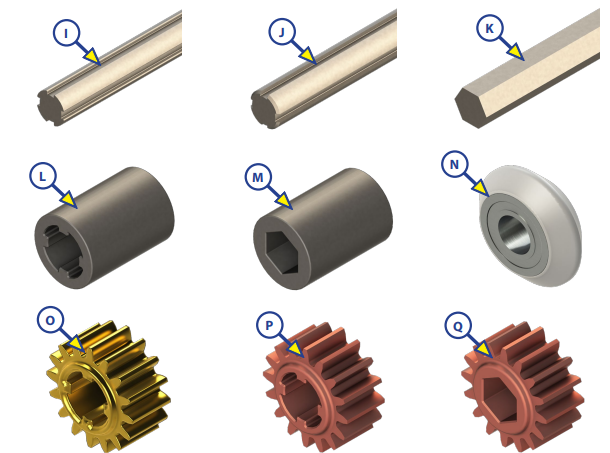
Callout | Part # | Description |
I | *238462 | Aluminum TorqueShaft |
J | *259065 | Steel TorqueShaft |
K | *295873 | Hex Torque Shaft |
L | 238461 | Coupler - Old Style (for 229466 Motor) |
Coupler - New Style (for 236575 Motor) | ||
M | 285083 | Hex Coupler |
N | *292801 | V-Roller Assembly |
O | 238893 | Spur Gear |
P | 292435 | Copper InfusedSpur Gear |
Q | 285085 | Hex Spur Gear |
NOTe:*Parts shownfor reference only.The part is not available for individual replacement. | ||
Callout | Part # | Description | Measurements |
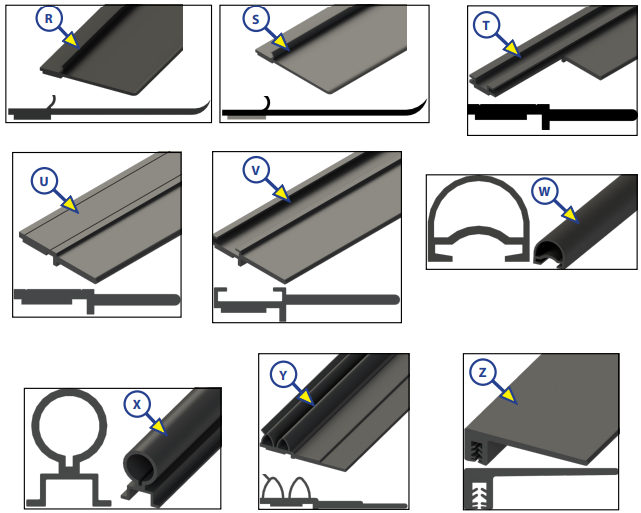
R | 156603 | Seal | 1" x 2 21/32" x 5/64" |
S | 132733 | Sweep Seal | 2 43/64" x 1/16" |
T | 239667 | EK Design Flap | 1 1/4" |
U | 240410 | Flat Side Wiper | 1 1/4" |
V | 240448 | KE Black Single Wiperwith Leg | 1 1/4" |
W | 260406 | KE Black Slide on D-Seal | - |
X | 240449 | KE Black Slide on Bulb Seal | - |
Y | 253344 | Winnebago Double Bulb Seal | - |
Z | 300614 | Slide-Out Seal | 144" |
IN-WALL SLIDE-OUT REPAIR KITS
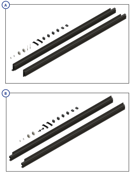
SLIDE-OUTS: Standard (With 1.56" Notch)
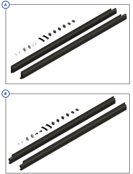
SLIDE-OUTS: Inverted (With 1.56" Notch)
Callout | Part # | Description |
A | 366154 | Clear Standard Fixed Repair Kit |
| 366209 | Black Standard Fixed Repair Kit | |
B | 366156 | Clear Standard Float Repair Kit |
| 366211 | Black StandardFloat Repair Kit |
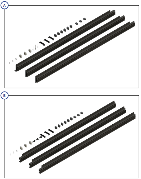
Callout | Part # | Description |
A | 366158 | Clear Inverted Fixed Repair Kit |
| 366212 | Black Inverted Fixed Repair Kit | |
B | 366159 | Clear Inverted Float Repair Kit |
| 366213 | Black Inverted Float Repair Kit |
Callout | Part # | Description |
A | 366160 | Clear Triple Fixed Repair Kit |
| 366214 | Black TripleFixed Repair Kit | |
B | 366161 | Clear Triple Float Repair Kit |
| 366215 | Black TripleFloat Repair Kit |
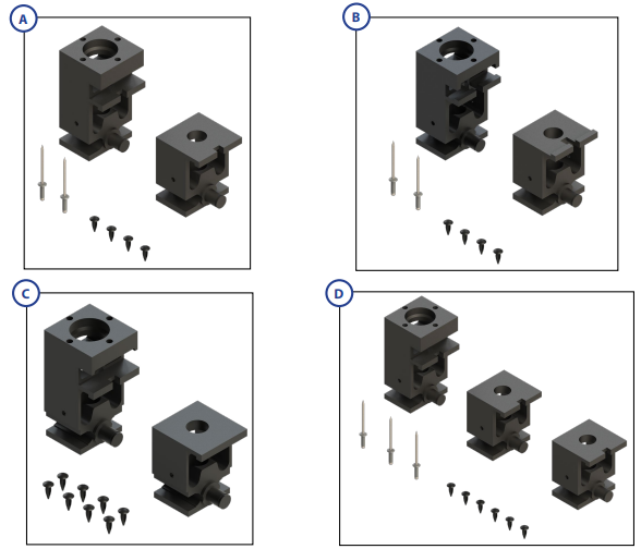
Callout | Part # | Description |
A | 379060 | Standard BearingBlock Repair Kit |
B | 379076 | Inverted Bearing Block Repair Kit |
C | 379077 | Narrow Bearing Block w/ Composite Gibs Repair Kit |
D | 379720 | Triple Bearing Block Repair Kit |
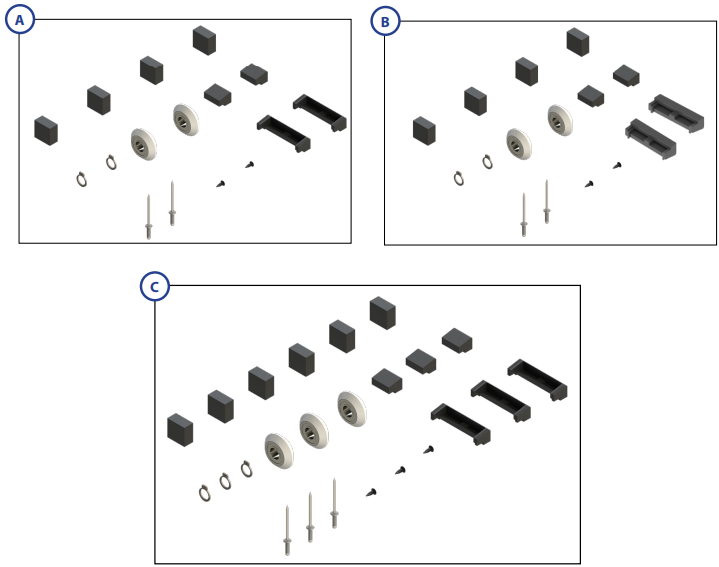
Callout | Kit # | Description |
A | 366121 | Standard (without gear racks) |
B | 366120 | Inverted (withoutgear racks) |
C | 366106 | Triple (without gear racks) |
Standard (With 1.56" Notch)
Bearing Block Repair Kit (With 1.56" Notch Gear Rack) If the bearing blocks need to be replaced, a repair kit that includes one upper and one lower bearing block, four plastic rivets, and 2 aluminum rivets is available. Part numbers are on the table below.
Note: Triple Bearing Block kit will include one upper and two lower bearing blocks, 6 plastic rivets, and 3 aluminum rivets.
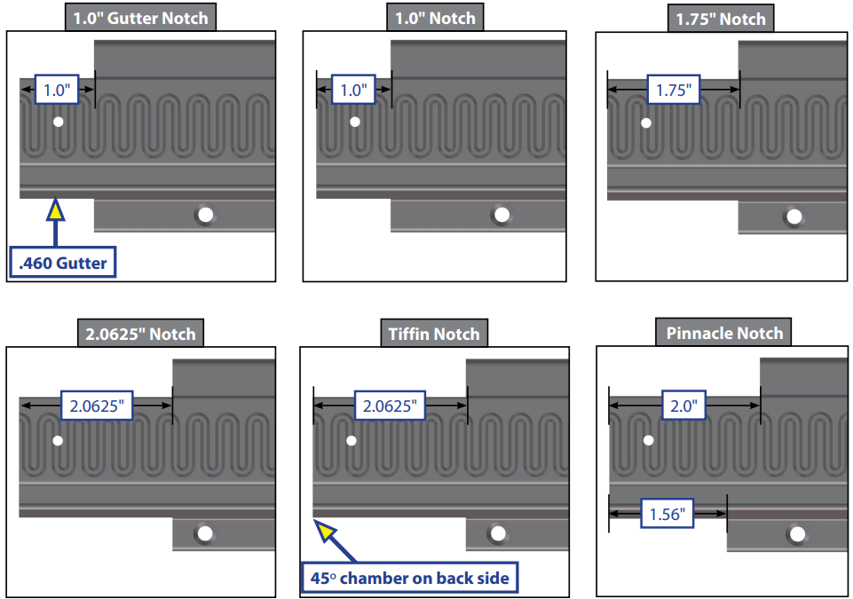
Custom
If the system being repaired has a different notch than the standard 1.56", use the images below to identify the notch, then contact LCI Parts at (574) 537-8900 for ordering assistance. (See next page for kit numbers.)
Note: If the gear rack being replaced has notches on both ends, the rack will need to be custom ordered.
Detailed Specifications
The Lippert LCI 236575 RV In-Wall Slide-Out Motor offers several key features, including:
- Seamless integration into the wall of the RV or trailer
- Schwintek slide-out components for reliable and smooth operation
- Easy installation with minimal modifications to the RV or trailer
- Available in various sizes to accommodate different RV and trailer designs
- Durable construction to withstand the rigors of the road
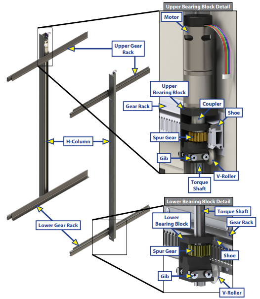
IN-WALL SLIDE-OUT ASSEMBLY
Operation
Prior To Operation
- Coach should be parked on the most level surface available.
- Leveling or stabilizing system should be actuated to ensure coach will not move during operation of slide-out system.
- Note: In the case of a motorized unit, ignition MUST be off to operate the slide-out.
- Be sure to keep all persons and pets clear of slide-out system during operation.
- Note: Install transit bars (if so equipped) on the slide-out room during storage and transportation. CAUTION: Always make sure that the slide-out room path is clear of people and objects before and during operation of the slide-out. Always keep away from the gear racks when the room is being operated.
Extending Slide-Out Room
- Level the unit.
- Note: In the case of a motorized unit, ignition MUST be off to operate the slide-out.
- Remove the transit bars (if so equipped).
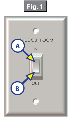
- Press and hold the IN/OUT switch (Fig. 1B) in the OUT position until the room is fully extended and stops moving.
- Note: It is important to continue to press the slide-out switch for a few seconds after the room is fully extended until the motor shuts off. The control will sense that the room has stopped and will shut off the motor after a few seconds.
- Release the switch, which will lock the room into position.
Retracting Slide-Out Room
- Note: In the case of a motorized unit, ignition MUST be off to operate the slide-out.
- Press and hold the IN/OUT switch (Fig. 1A) in the IN position until the room is fully retracted and stops moving.
- Note: It is important to continue to press the slide-out switch for a few seconds after the room is fully retracted until the motor shuts off. The control will sense that the room has stopped and will shut off the motor after a few seconds.
- Release the switch, which will lock the room into position.
Install the transit bars (if so equipped).
Controller Overview
(B Version)
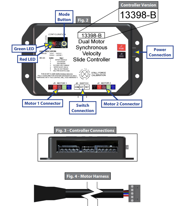
- Status LEDs: 2 LEDs, 1 green and 1 red, are provided to indicate current controller status and faults.
- Power Connection: 12V DC input. Unit will operate from 8V DC to 18V DC.
- Switch Connection: Spade connection for the switch wiring.
- Motor 1 Connector: Power and encoder input for motor 1.
- Motor 2 Connector: Power and encoder input for motor 2.
- Note: Version B motor harnesses have five wire in-line connectors at the controller and the molded connector at the motor end (Figs. 3 and 4). Wire colors match with color codes on control board. It does not matter which motor is 1 or 2.
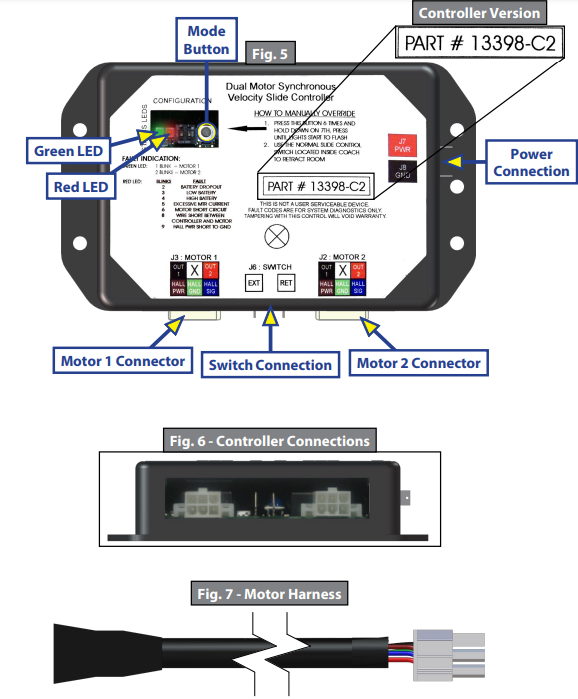
(C2 Version)
- Status LEDs: 2 LEDs, 1 green and 1 red, are provided to indicate current controller status and faults.
- Mode Button: Used to engage the electronic manual override.
- Power Connection: 12V DC input. Unit will operate from 8V DC to 18V DC.
- Switch Connection: Spade connection for the switch wiring.
- Motor 1 Connector: Power and encoder input for motor 1.
- Motor 2 Connector: Power and encoder input for motor 2.
Note: Motor harnesses have Molex connectors at the controller and a molded connector at the motor end (Figs. 6 and 7). Wire colors match with color codes on control board. It does not matter which motor is 1 or 2.
Motor and Controller Compatibility
| Part # | Controller Version | Controller Replacement | Motor(s) Used |
A (Daisy Chain) (Fig.8) | A Only | Round-Square (Fig. 14), Round-Round (Fig. 15A) | |
| B (Fig. 9) | B/C2* Only | Round Square(Fig. 14) |
C (Fig.10) | C/C2* Only |
Round-Round (Fig.15A, 15B), Round-Square Plate (Fig. 16) | |
C1 (Fig.11) | C1/C2* Only | ||
C2 (Fig. 12) | C2 | ||
D-0 (Fig. 13) | B/C1/C2 | ||
| 326876 | 8 Amp (Fig. 14) | 8 Amp Only | Round-Round (Fig.15B) |
NOTe: Always replace the motorin the systemwith the samemotor except theRound-Square Plate (Fig. 17),which is obsolete. That motor willbe replaced withthe Round-Round (Fig.16A, 16B). | |||
NOTe:(*) Denotes that (2) newmotor harnesses MUST be ordered, andre-wiring instructions MUST be used. See nextpage. | |||
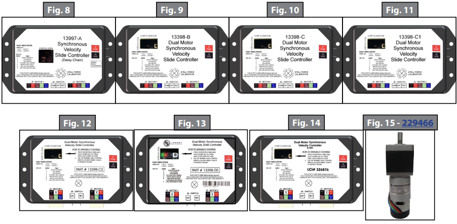
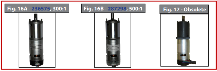
NOTE: Ensure that a 300:1 motor is replaced with a 300:1 motor (Fig. 16A), and that a 500:1 motor is replaced with a 500:1 motor (Fig. 16B).
Description
The Lippert LCI 236575 RV In-Wall Slide-Out Motor is a cutting-edge solution for RV and trailer manufacturers looking for a reliable and easy-to-install slide-out system. With its seamless integration into the wall of the RV or trailer, this system offers a sleek and modern appearance while providing a sturdy and durable structure for the slide-out. The Schwintek slide-out components ensure smooth and reliable operation, while the easy installation process minimizes modifications to the RV or trailer. This system is available in various sizes to accommodate different designs, making it a versatile solution for any manufacturer.
Rewiring Instructions
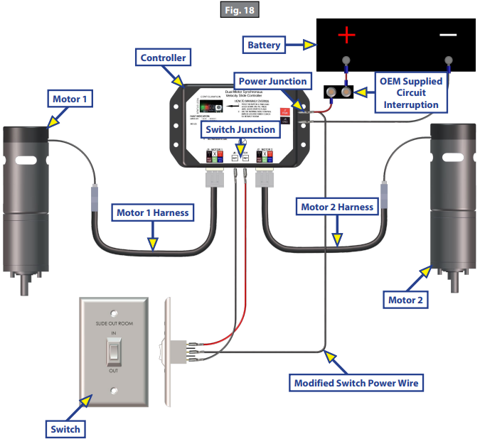
If it is necessary to replace a malfunctioning Rev. B, C, or C1 controller, it is recommended that the customer do so with a new Rev. D-0 controller. In order to properly rewire a Rev. B, C, or C1 controller to a new Rev. D-0 controller, the customer will need two new motor harnesses (one for each motor.) Additionally, it will be necessary to modify the power wire from the controller to the extend/retract switch by adapting the wire to piggyback the connection at the power junction. This wire comes from the positive side of the buss bar to the controller (Fig. 18).
Motors and Harnesses
Check for proper connections between the motors and harnesses (Fig. 19).
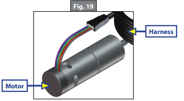
- Visually inspect the exposed harnesses to ensure they are not pinched or damaged.
- Note: Ribs on motor connector line up with notch inside of female connector on wiring harness. Color codes on wires also match (black to black, red to red, etc.)
Resynchronizing the Slide-Out Motors
- Fully extend the slide room using the switch. Keep the switch engaged until the motors shut down on their own.
- Retract the room 1-2 inches.
- Repeat steps 1 and 2 until both motors shut down at the same time. In many cases, two or three repetitions are necessary to re-sync the system.
- Fully extend the slide-out and keep the switch engaged until the motors shut down on their own.
- Fully retract the slide-out, again keeping the switch engaged until the motors shut down on their own.
- If both motors shut down at the same time at full extension and full retraction, the room is properly synchronized. If they do not shut down at the same time, repeat the process until they do.
Extend and Retract Switch Connections
- Rev. A - Rev. C1 Controllers: Common connection on controller goes to common connection on extend and retract switch.
- Rev. C2 and 8 amp Controllers: Extend and retract connections on the controller go to the extend and retract terminals on the switch. Switch is powered by the OEM supplied 12V DC power source.
Power and Ground Connections At the Controller
Power and ground are supplied to the controller through the spade terminals located on the right-hand side of the controller (Figs. 2 and 5 - Power Connection). 12V DC is recommended. A 10ga wire is the minimum size recommended. A 30 amp resetting or blade fuse is required (OEM supplied).
Troubleshooting
Checking Circuit Breakers
The IN-WALL Slide-out requires a minimum of a 30-amp circuit breaker. Check the 12-volt circuit breaker box for blown circuit breakers, and replace any if necessary. Consult the RV manufacturer's documentation for the location of the 12-volt circuit breaker box, and the location of the IN-WALL® Slide-out controller’s circuit breaker. If the circuit breaker blows immediately upon replacement, there is a problem with the wiring to the IN-WALL® Slide-out controller. Have qualified service personnel check and repair.
Obstructions
Check outside the RV for possible obstructions: tree, post, car, etc. Check inside the RV for any obstructions: luggage, furniture, open cabinets, etc. Also, check for smaller objects that may be wedged under the floor or in the sides of unit. Remove obstructions before proceeding.
Debris In the Rack
Check the sides of the slide room for any dirt or debris. Small dirt clumps or metal shavings can cause the spur gear to bind up and stop the movement of the slide-out. Use compressed air or a dry brush to remove any dirt or debris from the rack before attempting to actuate the system again.
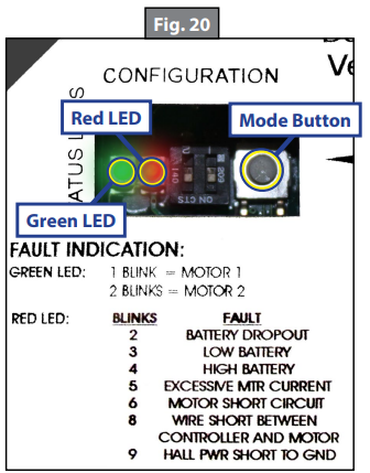
Error Codes
During operation when an error occurs, the board will use the LEDs to indicate where the problem exists (Fig. 20). For motor-specific faults the green LED will blink 1 time for motor 1, and 2 times for motor 2. The red LED will blink from 2 to 9 times depending on the error code (Fig. 21).
When an error code is present, the board needs to be reset. Energizing the extend/retract switch (Fig. 1) resets the board. Energize the extend/retract switch again for normal operation.
| Fig. 21 - errorCode Description |
| ||
Error Code | Name | Description | ||
2 |
Battery Drop Out | Battery capacity lowenough to drop below6 volts while running or short in switch wiring. | ||
3 | Low Battery | Voltage below8 volts at start of cycle. | ||
4 | High Battery | Voltage greaterthan 18 volts. | ||
5 | Excessive Motor Current | High amperage, also indicated by 1 side of slide continually stalling. | ||
6 | Motor Short Circuit | Motor or wiring to motor has shorted out. | ||
8 | Wire Short Between Controller and Motor | Encoder is not providing a signal. Thisis usually a wiring problem. | ||
9 | Hall Power Short To Ground | Power to encoder has been shorted to ground. This is usually a wiring problem. | ||
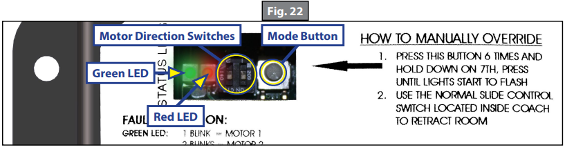
Electronic Manual Override (Controllers C-1, C-2 and D-0 Only)
- Note: See (Fig. 22) for locations of the mode button and LEDs.
- Press the mode button on the controller six times and hold on the seventh for five seconds to enter electronic manual override mode.
- Use the extend/retract switch to move both motors in or out.
- Note: Over-current and short circuit detection are still enabled. Electronic manual override provides 12V directly to both motors.
- To exit the mode, push and hold the mode button until the LEDs begin to blink simultaneously. Exiting the override mode resets the motor positions (you will have to resync motors).
- Note: During this override procedure the motors are not synchronized. Visually watch the room: if one side is moving significantly slower than the other (or not at all) then immediately stop and use the "Motor Disengagement Procedure" below.
Motor Disengagement Procedure
- Remove motor retention screws located near the top of each vertical column on the outside of the coach (under bulb seal if equipped with bulb seal on column).
- Locate motor.
- A. On units built prior to 2011: Bend back wipe seal from outside of coach.
- B. On units from 2011 to current: See slot in H-column on the inside of the coach.
- Pull motor up until disengaged (roughly 1/2"). A flat-head screwdriver can be used to pry the motor up.
- Reinstall motor retention screw to hold motor in place or remove motor.
Low Voltage
The Lippert IN-WALL Slide-out Controller is capable of operating the room with as little as 8 volts. But at these lower voltages the amperage requirement is greater. Check voltage at the controller, see Figs. 2 and 5 for the location of power connections. If the battery is low, it needs to be charged or the unit should be plugged into shore power or the generator can be run, if equipped. It may be possible to "jump" the RV's battery temporarily to extend or retract the room. Consult the RV manufacturer's owners manual.
Note: Always connect directly to the battery and never to the controller power connections.
Motor Direction Switches
- Motor direction switches (Fig. 22) are used to change the direction of individual motors. If when trying to extend or retract the room, one side goes in and the other side goes out, then there is a problem in the wiring. The motor direction switches can be used to correct this problem. The left switch controls motor 2 and the right switch controls motor 1. If motor 1 is going in the wrong direction then change switch 1’s position. If motor 2 is going in the wrong direction then change switch 2’s position.
The motor direction switches can also be used to change the direction of the extend/retract switch. If the room extends when the extend/retract switch is moved to the retract position, its direction can be reversed by moving both switch 1 and switch 2 to their opposite positions. This feature can be used if it is more convenient to change the motor direction switches than to rewire the extend/retract switch.
Lippert LCI 236575 RV In-Wall Slide-Out Motor System Maintenance
It is recommended that when operating In-Wall Slide-out system in harsh environments (road salt, ice buildup, etc.) that the gear racks and seals be kept clean and free of debris. They can be washed with mild soap and water.
Note: No grease or lubrication is necessary, and in some situations may be detrimental to the long-term dependability of the system.
Setup Guide
Setting up the Lippert LCI 236575 RV In-Wall Slide-Out Motor is a straightforward process. First, make sure the RV or trailer is properly prepared for installation, including any necessary modifications to the wall and floor. Next, install the Schwintek components, following the instructions provided by Lippert. Finally, test the slide-out to ensure proper operation, making any necessary adjustments as needed. For more detailed instructions, consult the Lippert installation manual.
Safety Information
WARNING: Failure to act in accordance with the following may result in death, serious injury, coach or property damage.
The In-Wall Slide-out System is intended for the sole purpose of extending and retracting the slide-out room. Its function should not be used for any purpose or reason other than to actuate the slide-out room. To use the system for any reason other than what it is designed for may result in death, serious injury or damage to the coach.
Before actuating the system, please keep these things in mind:
- Parking locations should be clear of obstructions that may cause damage when the slide-out room is actuated.
- Be sure all persons are clear of the coach prior to the slide-out room actuation.
- Keep hands and other body parts away from slide-out mechanisms during actuation.
- To optimize slide-out actuation, park coach on solid and level ground.
Troubleshooting
Common problems with the Lippert LCI 236575 RV In-Wall Slide-Out Motor may include:
- Difficulty opening or closing the slide-out
- Strange noises during operation
- Uneven or rough movement
- Leaks or water damage
- Electrical issues
To troubleshoot these problems, consult the Lippert installation manual and follow their recommended solutions. If the problem persists, contact Lippert customer support for further assistance. It is important to follow all safety guidelines and warnings when operating and maintaining the system to prevent any accidents or damage.
Pros & Cons
Pros
- Seamless integration into the wall of the RV or trailer
- Schwintek slide-out components for reliable and smooth operation
- Easy installation with minimal modifications to the RV or trailer
- Durable construction to withstand the rigors of the road
- Available in various sizes to accommodate different RV and trailer designs
Cons
- Higher cost compared to traditional slide-out systems
- May require modifications to the RV or trailer for proper installation
- Limited availability in the market
Customer Reviews
Customers have praised the Lippert LCI 236575 Schwintek In-Wall Slide-Out Motor for its sleek appearance, reliable operation, and easy installation process. However, some have noted issues with water leaks and electrical problems. Overall, the Lippert Schwintek In-Wall Slide-Out system has received positive reviews from customers, with an average rating of 4.5 out of 5 stars.
Faqs
What is the Lippert Schwintek In-Wall Slide-Out system?
How does the Lippert Schwintekwork?
How much does the system cost?
Where can I purchase the In-Wall Slide-Out system?
What are the benefits of the Lippert?
What are the common problems with the Lippert Schwintek In-Wall?
How do I troubleshoot issues with the Slide-Out system?
What are the pros and cons of the LCI 236575?
What is the average rating of the Lippert?
What is the warranty of the Slide-Out system?
Leave a Comment