Matthews Fan Company Patricia-3 Ceiling Fan User Manual
Content
Introduction
The Matthews Fan Company Patricia-3 Ceiling Fan is a perfect blend of elegance and functionality, designed to enhance both commercial and residential spaces. Crafted from durable cast aluminum and heavy stamped steel, it features solid wood blades available in various finishes, including walnut and matte black. With a whisper-quiet DC motor, this fan circulates air efficiently while an eco-friendly LED light kit adds sophistication. Priced at $499, the Patricia-3 is a stylish and efficient choice for any room.
Specifications
- Number of Blades: 3
- Blade Material: Wood
- Motor Type: High-efficiency DC motor
- Speed Settings: 6 reversible speeds
- Light Kit Compatible: Yes, with optional LED light kit
- Remote Control Included: Yes, with wall mount and handheld remote options
- Energy Efficiency: Energy Star certified
- Warranty: 5-year limited warranty on motor, 1-year limited warranty on other parts
TOOLS AND MATERIALS REQUIRED
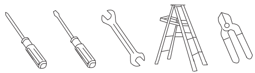
- Philips screwdriver
- Blade screwdriver
- 11 mm wrench
- Step ladder
- Wire cutters
PACKAGE CONTENTS
Unpack your fan and check the contents.
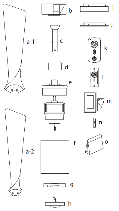
You should have the following items:
- a-1. Blade set (3) (for PA3-CR)
- a-2. Blade set (5) (for PA5-CR)
- Hanger bracket assembly
- Ball / down rod assembly
- Coupling cover
- Fan motor assembly
- Fan housing
- Mounting plate
- 16W LED light kit
- Glass shade assembly
- Additional metal light cover
- Hand-held transmitter+holder+2 mounting screws
- Wall transmitter incl. 2 mounting screws and 3 wire nuts
- Wall plate incl. 1 face plate and 2 mounting screws
- 12V batteries (2)
- Package hardware
- Mounting hardware:
- wood screws (2), screws (2),
- lock washers (2), washers (2),
- star washers (2), wire nuts (3)
- Blade attachment hardware:
- screws (11),
- lock washers (11),
- flat washers (11)
- Mounting hardware:
Please do not use any electric or battery powered tools in the assembly and installation of this or any Matthews Fan Company product.
SAFETY RULES
- To reduce the risk of electric shock, insure electricity has been turned off at the circuit breaker or fuse box before beginning.
- All wiring must be in accordance with the National Electrical Code and local electrical codes. Electrical installation should be performed by a qualified licensed electrician.
- WARNING: To reduce the risk of electrical shock and fire, do not use this fan with any solid-state fan speed control device.
- WARNING: To Reduce The Risk Of Fire, Electric Shock, Or Personal Injury, Mount To Outlet Box Marked Acceptable for Fan Support of 15.9 kg (35 lbs) or less And Use Mounting Screws Provided With The Outlet Box. Most outlet boxes commonly used for the support of lighting fixtures are not acceptable for fan support and may need to be replaced, consult a qualified electrician if in doubt.
- The fan must be mounted with a minimum of 7 feet clearance from the trailing edge of the blades to the floor.
- To operate the reverse function on this fan, press the reverse button while the fan is running.
- Avoid placing objects in the path of the blades.
- To avoid personal injury or damage to the fan and other items, be cautious when working around or cleaning the fan.
- Do not use water or detergents when cleaning the fan or fan blades. A dry dust cloth or lightly dampened cloth will be suitable for most cleaning.
- After marking electrical connections, spliced conductors should be turned upward and pushed carefully up into outlet box. The wires should be spread apart with the grounded conductor and the equipment - grounding conductor on one side of the outlet box.
- Electrical diagrams are reference only. Light kit that are not packed with the fan must be UL Listed and marked suitable for use with the model fan you are installing. Switches must be UL General Use Switches. Refer to the Instructions packaged with the light kits and switches for proper assembly.
WARNING
TO REDUCE THE RISK OF PERSONAL INJURY, DO NOT BEND THE BLADE BRACKETS (ALSO REFERRED TO AS FLANGES) DURING ASSEMBLY OR AFTER INSTALLATION. DO NOT INSERT OBJECTS IN THE PATH OF THE BLADES.
NOTE
SUITABLE FOR USE IN DAMP LOCATIONS!
MOUNTING OPTIONS
If there isn't an existing UL listed mounting box, then read the following instructions. Disconnect the power by removing fuses or turning off circuit breakers.
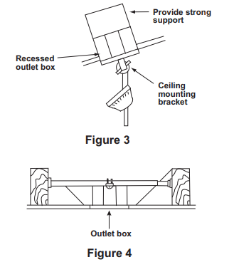
Secure the outlet box directly to the building structure. Use appropriate fasteners and building materials. The outlet box and its support must be able to fully support the moving weight of the fan 15.9 kgs (35lbs) or less. Do not use plastic outlet boxes. Figures 1,2 and 3 are examples of different ways to mount the outlet box.
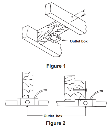
Note: The Fig. 3 are for use for downrod style only.
Note: You may need a longer downrod to maintain proper blade clearance when installing on a steep, sloped ceiling. (Fig. 3)
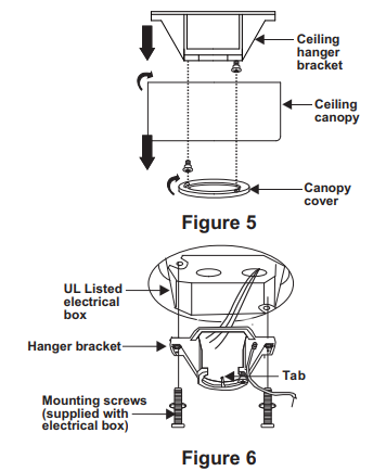
To hang your fan where there is an existing fixture but no ceiling joist, you may need an installation hanger bar as shown in Figure 4.
HANGING THE FAN
REMEMBER to turn off the power. Follow the steps below to hang your fan properly.
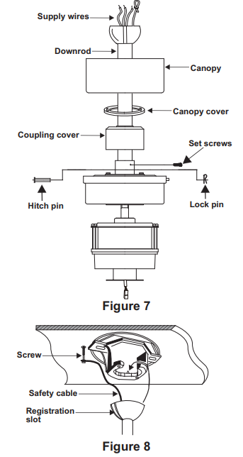
- Remove the decorative canopy bottom cover from the canopy by turning the cover counter clockwise. (Fig. 5)
- Remove the hanger bracket from the canopy by removing the 1 of 2 screws from the bottom of the hanger bracket and loosening the other one a half turn from the screw head. Next, turn the canopy counter clockwise to removing the hanger bracket from the canopy. (Fig. 5)
Secure the hanger bracket to the ceiling outlet box using screws and washers included with your outlet box. (Fig. 6)
- Loosen the two set screws and remove the hitch pin and lock pin from the central shaft/top coupling of the motor assembly. Doing so will allow the down rod to enter the central shaft. (Fig. 7)
- Route wires exiting from the top of the fan motor through the coupling cover, canopy cover and canopy and then through the ball/downrod. (Fig. 7)
- Align the holes at the bottom of the downrod with the holes in the collar on top of the motor housing. Carefully insert the hitch pin through the holes in the collar and downrod. Be careful not to jam the pin against the wiring inside the downrod. Insert the lock pin through the hole near the end of the hitch pin until it snaps into its locked position. (Fig. 7)
Warning/Caution: Failure to properly install lock pin as noted in step 6 could result in fan loosening and possibly falling. - Tighten two set screws on top of the fan motor firmly.
- Now lift the motor assembly into position and place the hanger ball into the hanger bracket. Rotate down rod until the "Check Tab" has dropped into the "Registration Slot" and the down rod and ball assembly seat firmly. The down rod and ball assembly should not rotate if this is donecorrectly. (Fig. 8)
An additional safety support is provided to prevent the fan from falling. Secure the safety cable to the ceiling joist with screw and washer. (Fig. 8)
MAKE THE ELECTRIC CONNECTIONS
NOTE: Your fan has included as standard equipment two types of controls: a hand held remote control and a wall mounted wall control. You may use both as long as the dip switches are calibrated the same. Select one of the controls at this moment for installation and programming of your fan.
Disconnect the power at the electrical box. Follow the steps below to connect the fan to your household wiring. Use the wire connecting nuts supplied with your fan. Secure the connectors with electrical tape. Make sure there are no loose strands or connections.
A. Hand-held remote control
- Connect the fan supply (black) wire to the black household supply wire as shown in Figure 9.
Connect the neutral fan (white) wire to the white neutral household wire. (Fig. 9)
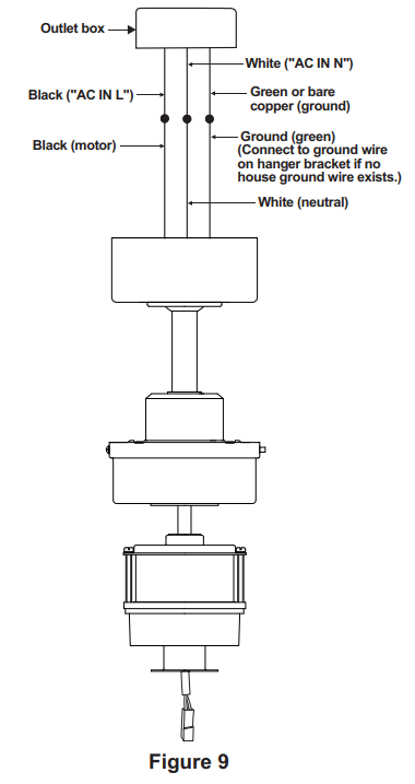
- Connect the fan ground wire (green) to the household ground wire.
- Check that the two plugs, large and small are making proper contact. One plug is small with only a single wire connection. The second plug is larger and connects multiple colored wires.
- After all splices are made, check to make sure there are no loose strands. As an additional precaution, we suggest securing the plastic wire connectors to the wires with electrical tape.
B. Wall mount remote control
- Fan wire connection
Connect the fan supply (black) wire to the black household supply wire (Conductor cable between the ceiling and wall outlet box). (Fig. 10)
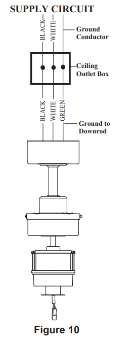
- Connect the neutral fan (white) wire to the white neutral household wire.
- Connect the fan ground wire (green) to the household ground wire.
- Check that the two plugs, large and small are making proper contact. One plug is small with only a single wire connection. The second plug is larger and connects multiple colored wires.
- After all connections are made, check to make sure there are no loose strands. As an additional precaution, we suggest securing the plastic wire connectors to the wires with electrical tape.
- Installing the wall control
- Remove the existing wall plate and the old switch from the wall outlet box. Wire nut the BLACK leads (hot) together and push back inside the outlet box.
Carefully tuck the wire connections inside the outlet box. Secure the wall control with the two wall switch screws provided. (Fig. 11)
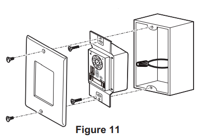
- Attach the wall plate over the wall control and secure with the two wall plate screws provided.
Disclaimer: If a wall switch is to be used, for the warranty to be valid, our included wall control needs to be installed to operate this fan.
Description
The Matthews Fan Company Patricia-3 Ceiling Fan stands out due to its sophisticated design and robust construction. The fan’s body and blades are made from high-quality materials, ensuring durability and longevity. The DC motor provides silent operation and high energy efficiency, making it an excellent choice for environmentally conscious consumers. The fan’s reversible function allows for year-round use, circulating warm air during winter and cool air during summer.
The optional LED light kit adds an extra layer of functionality, providing bright and energy-efficient lighting. The included remote control allows for easy adjustments of speed and light settings from anywhere in the room.
FINISHING THE INSTALLATION
STANDARD CEILING INSTALLATION
- Tuck connections neatly into ceiling outlet box.
Slide the canopy up to hanger bracket and place the key hole on the canopy over the screw on the hanger bracket, turn canopy until it locks in place at the narrow section of the key holes. (Fig. 12)
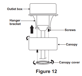
- Align the circular hole on canopy with the remaining hole on the hanger bracket, secure by tightening the two set screws. Note: Adjust the canopy screws as necessary until the canopy and canopy cover are snug.
Warning: Make sure tab at bottom of hanger bracket is properly seated in groove of hanger ball before attaching canopy to bracket. Failure to properly seat tab in groove could cause damage to electrical wiring.
INSTALLING THE FAN HOUSING
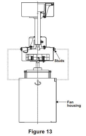
Raise the fan housing up against the mounting plate. The four supports inside the fan housing should be placed against the four studs on the mounting plate. Twist the fan housing clockwise until snug. (Fig. 13)
ATTACHING THE FAN BLADES
Fasten blade to motor using the flat washers, lock washers and screws supplied. (Fig. 14)
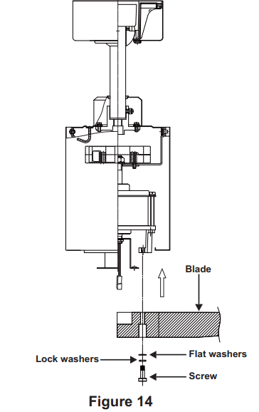
- Repeat process with other blades. Tighten each screw and make sure the blade is straight.
NOTE: This fan is supplied with two types of blades for installation. Please reference the important diagram (Fig. 15) when attaching your fan blades.
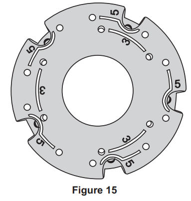
- The inner holes are for 3 blades. (for PA3)
- The outer holes are for 5 blades. (for PA5)
ATTACHING THE MOUNTING PLATE
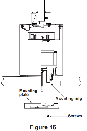
- Step 1. Remove 1 of the 3 screws from the mounting ring and keep it for future use. Loosen the other 2 screws. (Do not remove)
Step 2. Place the key holes on the mounting plate over the 2 screws previously loosened from the mounting ring, turn mounting plate until it locks in place at the narrow section of the key holes. Secure by tightening the 2 screws previously loosened and the one previously removed. (Fig. 16)
INSTALLING THE LIGHT KIT
REMEMBER: To disconnect the power.
If you do not plan to install the light kit with your fan at this time, skip step 1, 2, 3 & 4.
- Remove 1 of the 3 screws from the mounting plate and loosen the other 2 screws. (Do not remove)
Raise and hold the LED light kit close to the mounting plate and proceed to do the wire connections. Make the 2-pin wire connections:(Fig. 17)
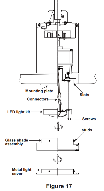
- Red to white
- Black to black
- Place the key holes from the light kit over the 2 screws previously loosened from the mounting plate, turn the light kit until it locks in place at the narrow section of the key holes. Secure by tightening the 2 screws previously loosened and the one previously removed. (Fig. 17)
- Raise the glass shade assembly up against the mounting plate. The three slots inside the mounting plate should be placed against the three studs on the glass shade assembly, and secure it to the mounting plate until snug.
- If installing the optional metal light cover, make sure is securely tighten.
NOTE: The metal light cover included with your fan is an option to replace the glass for the light in the event that you prefer not to use the light feature of your fan. The metal light cover is not necessary for the light operation; it can be saved for later use if desired.
PROGRAMMING YOUR FAN
Before programming takes place, fan must be fully assembled and mounted to the ceiling with blades attached. You must also choose which control you will be using for programming the fan, the remote or the wall control. No other wall control should be used with this fan but that which was included. Using another wall control other than ours will damage your fan and void your warranty.
Install one 23A/12V battery (included). To prevent damage to the transmitter, remove the battery if not used for long periods of time (Fig. 18 & 19).
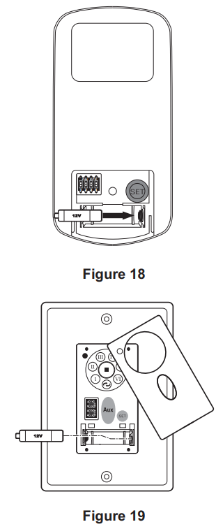
- a) Select the desired frequency from the transmitter.
Follow the below steps to set the remote control: The auto-learning function will only mandate within 60 seconds when turning the fan’s AC power ON. - b) From the wall or remote transmitter, Press and hold the “SET” button for about 5 seconds and release. If optional light kit is installed, the signal light on the wall control will come on when the button is pressed. The fan has completed the pairing process with the wall control and is ready for use.
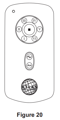
A. I, II, III, IV, V, and VI buttons:
These six buttons are used to set the fan speed as follows:
- I = minimum speed
- II = low speed
- III = medium-low speed
- IV = medium speed
- V = medium-high speed
- VI = high speed
B. ⬛ button:
This button turns the fan off.
C. 🔀 Reverse button:
This button is to control fan direction
D. Aux Light button:
This button is to control light ON or OFF and also controls the brightness setting.
E. SET code setting button:
Your DC brushless motor is equipped with automatically learned type remote control and a wall control. If two fans or more in a house, it is recommended that you not use the factory code settings. Change codes setting to any other combination of dip switch setting to avoid fan interference issues. Please refer the "D" "SET" code setting button section.
NOTE: If the self calibration test failed, turn the AC power off; restore power and process the self calibration test again.
NOTE: During self calibration test, the remote and the wall control are non-functional.
NOTE: The learning frequency function and self calibration test will continue to retain the last set frequency and calibration set even when the AC power is shut off. If the frequency is changed the self calibration test will occur again.
This receiver provides the following protective function:
- Lock Rotor Position: The DC motor has a built-in safety against a stalled or locked rotor condition (stalled blade rotation). If there is an obstruction or fault with the motor, the current monitoring function will automatically turn power off to the motor after 30 seconds. Remove the obstruction and turn the AC power off. Restore power and re-start fan motor.
- Over 80W protection: When the receiver detects motor power consumption which is greater than 80W, the receiver power will be stopped and operation will immediately discontinue. Wait for 5 seconds and then turn the receiver power back on.
OPERATING YOUR FAN
Speed settings for warm or cool weather depend on factors such as the room size. Ceiling height, number of fans and so on.
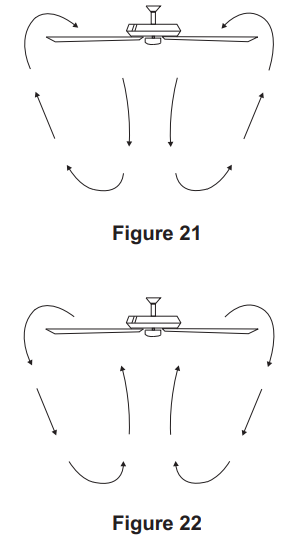
NOTE: To operate the reverse function on this fan, press the reverse button while the fan is running.
- Warm weather - (Forward) A downward airflow creates a cooling effect as shown in Fig. 21. This allows you to set your air conditioner on a warmer setting without affecting your comfort.
Cool weather - (Reverse) An upward airflow moves warm air off the ceiling area as shown in Fig. 22. This allows you to set your heating unit on a cooler setting without affecting your comfort.
Setup Guide
To set up the Matthews Fan Company Patricia-3 Ceiling Fan, start by ensuring all necessary components are included in the package. Follow these steps:
- Turn off the power to the ceiling fan at the electrical panel.
- Remove any existing ceiling fixtures or fans.
- Install the mounting bracket securely to the ceiling.
- Hang the fan motor housing from the mounting bracket.
- Attach the blades to the fan hub according to the manufacturer’s instructions.
- Connect the wiring carefully, ensuring all connections are secure and insulated.
- Turn on the power and test the fan at each speed setting.
For remote control setup, refer to the user manual for specific pairing instructions.
CARE OF YOUR FAN
Here are some suggestions to help you maintain your fan
- Because of the fan's natural movement, some connections may become loose. Check the support connections, brackets, and blade attachments twice a year. Make sure they are secure. (It is not necessary to remove fan from ceiling.)
- Clean your fan periodically to help maintain its new appearance over the years. Use only a soft brush or lint-free cloth to avoid scratching the finish. The plating is sealed with a lacquer to minimize discoloration or tarnishing. Do not use water when cleaning. This could damage the motor, or the wood, or possibly cause an electrical shock.
- You can apply a light coat of furniture polish to the wood blades for additional protection and enhanced beauty. Cover small scratches with a light application of shoe polish.
- There is no need to oil your fan. The motor has permanently lubricated bearings.
IMPORTANT: MAKE SURE THE POWER IS OFF AT THE ELECTRICAL PANEL BOX BEFORE YOU ATTEMPT ANY REPAIRS. REFER TO THE SECTION "MAKING ELECTRICAL CONNECTIONS".
Matthews Fan Company Patricia-3 Ceiling Fan Troubleshooting
| Problem | Solution |
|---|---|
| Fan will not start. | 1. Check circuit fuses or breakers. 2. Check line wire connections to the fan and switch wire connections in the switch housing. CAUTION: Make sure main power is off. 3. Check that the battery of the remote is functional. 4. Check to make sure all receiver plugs are connected at top of motor. 5. Re-do steps for programming on page 7. |
| Fan is noisy. | 1. Make sure all motor housing screws are snug. 2. Ensure screws that attach the fan blade bracket to the motor hub are tight. 3. Ensure wire nut connections are not rubbing against each other or the interior wall of the switch housing. CAUTION: Make sure main power is off. 4. Allow a 24-hour "breaking-in" period for new fans. 5. If using an optional light kit, ensure screws securing the light plate are tight. 6. If using solid-state variable speed controls, choose another type of control if issues persist. 7. Ensure the upper canopy is a short distance from the ceiling, not touching it. |
| Remote control malfunction. | 1. Do not connect the fan to a wall-mounted variable speed control; use provided wall control instead. 2. Ensure dip switches are set correctly. |
| Fan wobble. | 1. Check that all blade and blade arm screws are secure. 2. Most wobbling problems arise from unequal blade levels; measure each blade's distance from a fixed point on the ceiling to ensure they are equal within 1/8". 3. If wobble persists, interchange two adjacent blades to redistribute weight for smoother operation. WARNING: To reduce risk of injury, do not bend blade arms during installation or cleaning, and do not insert objects between rotating blades. |
| Fan has jerky movement | 1. Turn off AC power to fan, and re-do programming steps on page 10. 2. If jerky movement continues, verify both motor wire plugs are properly connected. |
| Fan has lost its programming repeatedly | 1. Turn off AC power to fan, and re-do programming steps on page 10. 2. Do not turn off fan from wall switch; use only remote to regulate fan. |
Warranty
MATTHEWS-GERBAR, LTD. DBA MATTHEWS FAN COMPANY LIFETIME LIMITED WARRANTY. warranted by Matthews-Gerbar, Ltd. to the original user against defects in workmanship or materials under normal use and inside or outside damp location installation for: Motors: Lifetime of original purchaser: Labor & Component parts: (lights, finish, blades, etc…): one year after date of purchase https://matthewsfanco.com/
Pros & Cons
Pros
- Elegant Design: The Patricia-3 features a unique and stylish design that complements various decor styles.
- Energy Efficiency: The DC motor is highly efficient and Energy Star certified.
- Quiet Operation: The fan operates silently due to its advanced motor technology.
- Remote Control: Includes a convenient remote control for easy adjustments.
- Durable Construction: Made from high-quality materials for long-lasting performance.
Cons
- Higher Price Point: Compared to other ceiling fans on the market, it is relatively expensive.
- Complex Installation: May require professional installation due to its advanced features.
- Limited Color Options: Available in fewer color options compared to some other models.
Customer Reviews
Customers have praised the Matthews Fan Company Patricia-3 Ceiling Fan for its stylish appearance and quiet operation. Many have noted the ease of use with the remote control and the significant energy savings. However, some reviewers have mentioned that the installation process can be complex and time-consuming.
Common complaints include the higher price point and limited color options available. Despite these minor drawbacks, the overall satisfaction rate among customers remains high due to its performance and durability.
Faqs
Is the Patricia-3 Ceiling Fan energy efficient?
Does the Matthews Fan Company come with a light kit?
How many speed settings does the Matthews Fan have?
What type of motor does the Patricia-3 use?
Is professional installation required for the Patricia-3 Ceiling Fan?
What warranty does the Matthews Fan Company offer for the Ceiling Fan?
Are there any safety precautions I should take when installing or using the Matthews Fan Company Patricia-3 Ceiling Fan?
Leave a Comment