Nordictrack C700 Treadmill NTL16915.4 User Manual
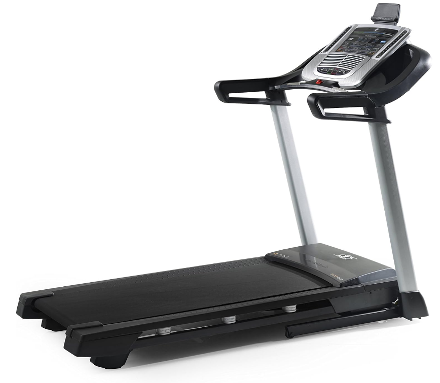
Content
Introduction
The NordicTrack C700 Treadmill NTL16915.4 is designed for an effective and enjoyable at-home workout experience. Featuring a foldable design, it includes a 7-inch multi-window LED display and access to iFIT, providing thousands of on-demand workouts. With a maximum speed of 10 miles per hour and an incline range of 0% to 10%, it caters to various fitness levels. Manufactured by NordicTrack, this treadmill is priced at approximately $799, making it a solid choice for those seeking quality and versatility in their fitness routine.
BEFORE YOU BEGIN
The C 700 treadmill provides an impressive selection of features designed to make your workouts at home more effective and enjoyable.
For your benefit, read this manual carefully before you use the treadmill. If you have questions after reading this manual, please see the front cover of this manual. To help us assist you, note the product model number and serial number before contacting us. The model number and the location of the serial number decal are shown on the front cover of this manual.
Before reading further, please familiarize yourself with the parts that are labeled in the drawing below.
PART IDENTIFICATION CHART
Use the drawings below to identify small parts used for assembly. The number in parentheses below each draw-ing is the key number of the part, from the PART LIST near the end of this manual. The number following the key number is the quantity used for assembly.
Note: If a part is not in the hardware kit, check to see whether it is preattached. Extra parts may be included.
Parts List
| No. | Qty | Description |
|---|---|---|
| 1 | 18 | #8 x 1/2" Screw |
| 2 | 39 | #8 x 3/4" Screw |
| 3 | 1 | 5/16" x 2 1/4" Bolt |
| 4 | 6 | 5/16" x 3/4" Screw |
| 5 | 2 | #10 Star Washer |
| 6 | 1 | 5/16" x 1 3/4" Bolt |
| 7 | 4 | 3/8" x 2 3/8" Screw |
| 8 | 1 | Key/Clip |
| 9 | 2 | #10 x 3/4" Screw |
| 10 | 9 | #8 x 1/2" Silver Screw |
| 11 | 10 | 5/16" Star Washer |
| 12 | 2 | 3/8" Washer |
| 13 | 8 | 3/8" Star Washer |
| 14 | 18 | #8 x 3/4" Truss Head Screw |
| 15 | 3 | 1/4" x 2 1/2" Screw |
| 16 | 1 | 3/8" x 1 1/2" Bolt |
| 17 | 2 | 3/8" x 1 1/2" Wheel Bolt |
| 18 | 1 | Console Frame |
| 19 | 4 | #8 x 7/16" Screw |
| 20 | 2 | 5/16" Motor Screw |
| 21 | 2 | 3/8" Pin |
| 22 | 2 | 3/8" x 1 1/8" Bolt |
| 23 | 4 | 5/16" x 1 3/4" Shoulder Bolt |
| 24 | 2 | #8 Star Washer |
| 25 | 2 | Wheel |
| 26 | 2 | Cable Tie |
| 27 | 1 | Right Tray |
| 28 | 4 | 5/16" x 2 1/2" Screw |
| 29 | 1 | 3/8" x 1 3/4" Hex Head Bolt |
| 30 | 4 | 5/16" Flat Washer |
| 31 | 1 | Right Inner Base Cover |
| 32 | 2 | Incline Motor Spacer |
| 33 | 6 | 3/8" Jam Nut |
| 34 | 6 | 5/16" Nut |
| 35 | 13 | 1/4" Nut |
| 36 | 1 | Left Tray |
| 37 | 6 | #8 x 5/8" Screw |
| 38 | 4 | #8 x 5/8" Machine Screw |
| 39 | 6 | Isolator |
| 40 | 2 | Rear Foot |
| 41 | 1 | Latch Crossbar |
| 42 | 1 | Left Foot Rail |
| 43 | 1 | Caution Decal |
| 44 | 1 | Walking Platform |
| 45 | 1 | Walking Belt |
| 46 | 2 | Belt Guide |
| 47 | 1 | Right Rear Foot |
| 48 | 4 | Cable Tie |
| 49 | 1 | Drive Roller/Pulley |
| 50 | 2 | 1/4" x 1 1/4" Screw |
| 51 | 2 | 9/32" Plastic Bushing |
| 52 | 4 | 3/8" Plastic Bushing |
| 53 | 1 | Storage Latch |
| 54 | 1 | Drive Motor |
| 55 | 1 | Motor Belt |
| 56 | 1 | Frame |
| 57 | 1 | Left Rear Foot |
| 58 | 1 | Console Ground Wire |
| 59 | 4 | Rubber Cushion |
| 60 | 1 | Right Foot Rail |
| 61 | 1 | Idler Roller |
| 62 | 2 | 3/8" x 1 3/4" Screw |
| 63 | 2 | 3/8" x 1 1/4" Screw |
| 64 | 1 | Console Base |
| 65 | 1 | Motor Hood |
| 66 | 1 | Hood Accent |
| 67 | 2 | Incline Frame Spacer |
| 68 | 9 | Clip |
| 69 | 1 | Incline Motor |
| 70 | 1 | Incline Frame |
| 71 | 2 | Frame Spacer |
| 72 | 1 | Controller |
| 73 | 1 | Controller Plate |
| 74 | 1 | Power Cord Grommet |
| 75 | 1 | Power Switch |
| 76 | 1 | Power Cord |
| 77 | 1 | Grommet |
| 78 | 1 | Belly Pan |
| 79 | 1 | Left Handrail Cover |
| 80 | 1 | Console |
| 81 | 1 | Upright Wire |
| 82 | 1 | Left Base Cover |
| 83 | 1 | Right Base Cover |
| 84 | 1 | Controller Clamp |
| 85 | 1 | Right Handrail Cover |
| 86 | 2 | Handrail |
| 87 | 1 | Left Outside Handrail Cover |
| 88 | 1 | Left Inside Handrail Cover |
| 89 | 1 | Left Upright |
| 90 | 1 | Right Upright |
| 91 | 2 | Warning Decal |
| 92 | 2 | Console Clamp |
| 93 | 1 | Pulse Crossbar |
| 94 | 1 | Base |
| 95 | 1 | Right Inside Handrail Cover |
| 96 | 1 | Right Outside Handrail Cover |
| 97 | 2 | Base Pad |
| 98 | 1 | Tablet Holder |
| 99 | 1 | Left Inner Base Cover |
| * | - | User’s Manual |
Note: Specifications are subject to change without notice. For information about ordering replacement parts, see the back cover of this manual. *These parts are not illustrated.
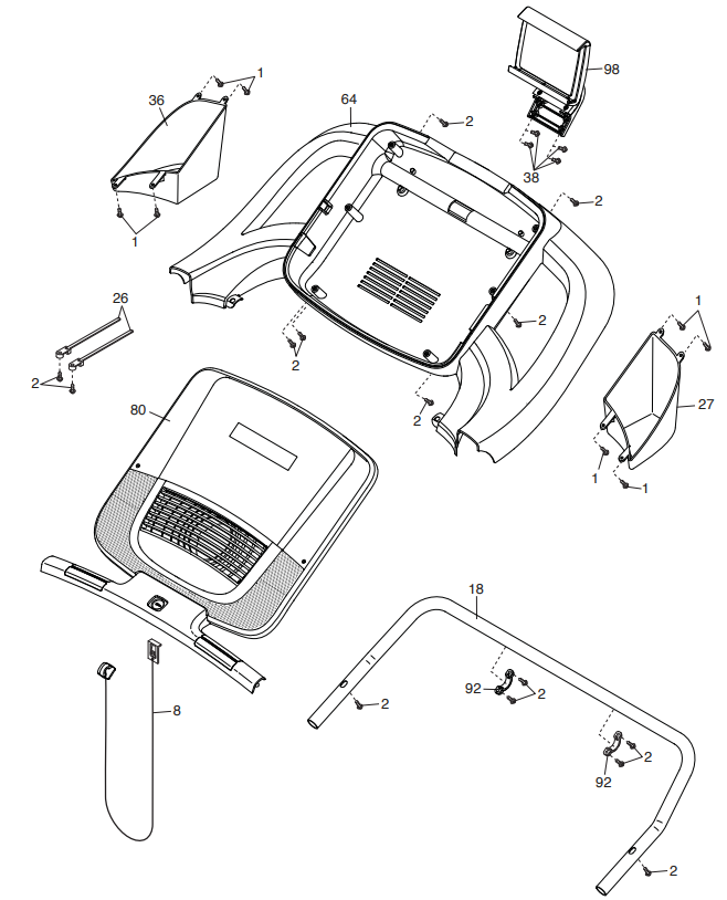
EXPLODED DRAWING A
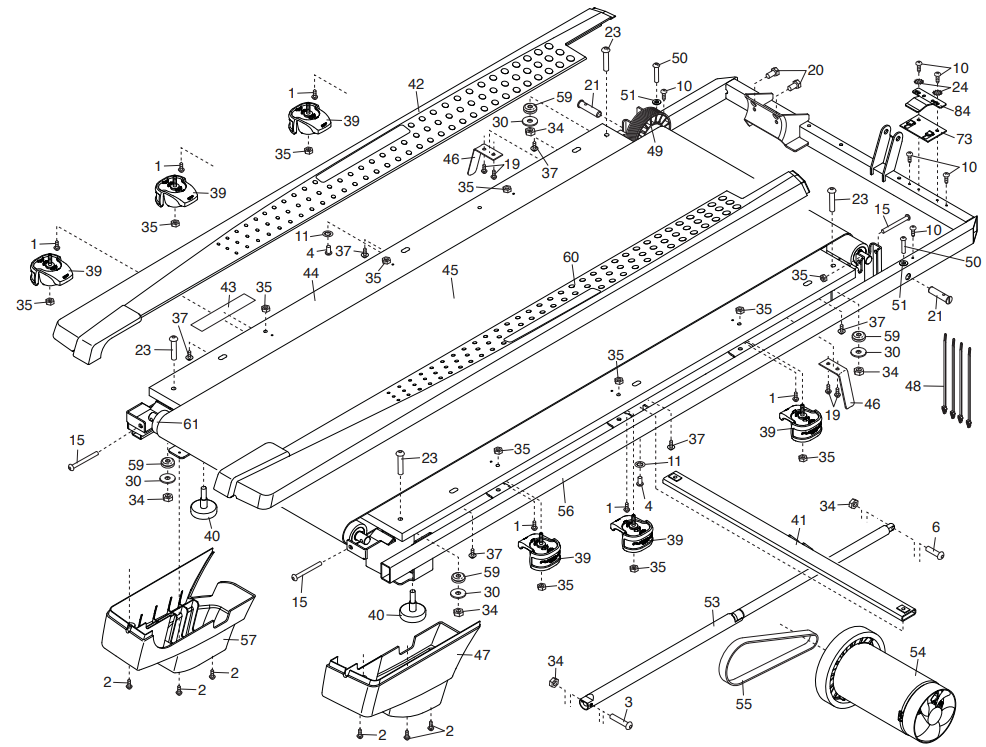
EXPLODED DRAWING B
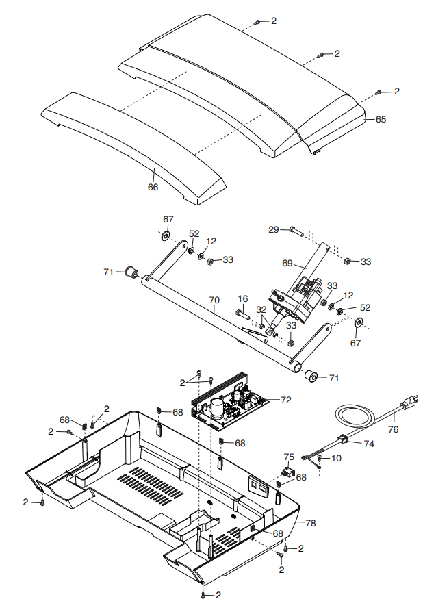
EXPLODED DRAWING C
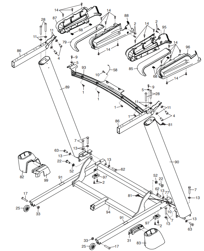
EXPLODED DRAWING D
Specifications
The NordicTrack C700 Treadmill boasts several key features that make it a standout in its class:
- 2.75 HP DurX Commercial Plus Motor
- 0-10 MPH Speed Range
- 0-10% Incline Adjustment
- 7-inch HD Touchscreen Display
- Bluetooth Connectivity and iFit Compatibility
- Spacious 20" x 55" Running Deck
- Heart Rate Monitoring with Handgrip Sensors
- Folding Design for Easy Storage
- Weight Capacity of 300 lbs
Description
The NordicTrack C700 Treadmill is designed with user comfort and convenience in mind. The 7-inch HD touchscreen display allows for easy navigation through various workout programs and real-time monitoring of your performance metrics such as speed, incline, distance, calories burned, and heart rate. The treadmill also features a spacious 20" x 55" running deck, providing ample room for users of all sizes to move comfortably during their workouts.
The robust 2.75 HP motor ensures smooth operation at any speed or incline level, while the foldable design makes it easy to store when not in use. Additional features include heart rate monitoring via handgrip sensors and built-in speakers for an immersive workout experience.
ASSEMBLY
- Assembly requires two persons.
- Place all parts in a cleared area and remove the packing materials. Do not dispose of the packing materials until you fi nish all assembly steps.
- After shipping, there may be an oily substance on the exterior of the treadmill. This is normal. If there is an oily substance on the treadmill, wipe it off with a soft cloth and a mild, non-abrasive cleaner.
- Left parts are marked “L” or “Left” and right parts are marked “R” or “Right.”
- To identify small parts, see page 7.
- Assembly requires the following tools:
- the included hex keys
- one Phillips screwdriver
To avoid damaging parts, do not use power tools.
- Go to my.nordictrack.com on your computer and register your product.
- activates your warranty
- saves you time if you ever need to contact Customer Care
allows us to notify you of upgrades and offers
Note: If you do not have Internet access, call Customer Care (see the front cover of this manual) and register your product.
- Make sure that the power cord is unplugged.
Remove the tie securing the Upright Wire (81) to the front of the Base (94).
Next, identify the Right Upright (90). Have a sec-ond person hold the Right Upright near the Base (94).
See the inset drawing. Tie the wire tie (A) in the Right Upright (90) securely around the end of the Upright Wire (81). Then, insert the Upright Wire into the lower end of the Right Upright as you pull the other end of the wire tie through the Right Upright. Lay the Right Upright (90) near the Base (94). Press the Grommet (77) into the square hole (B) in the Right Upright (90). Make sure not to pinch the ground wire.
If there is a screw (C) preattached to the Right Upright (90), remove and discard it.
Then, attach the ground wire (D) to the Right Upright (90) with a #8 x 1/2" Silver Screw (10).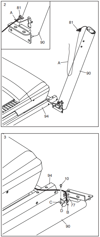
- Hold the Right Upright (90) against the Base (94). Make sure not to pinch the Upright Wire (81).
Attach the Right Upright (90) with two 3/8" x 2 3/8" Screws (7), a 3/8" x 1 1/4" Screw (63), a 3/8" x 1 3/4" Screw (62), and four 3/8" Star Washers (13) as shown; do not fully tighten the Screws yet.
Attach the Left Upright (not shown) in the same way.
Note: There are no wires on the left side. Identify the Left and Right Base Covers (82, 83).
Slide the Left Base Cover onto the Left Upright (89), and slide the Right Base Cover onto the Right Upright (90). Do not press the Base Covers into place yet.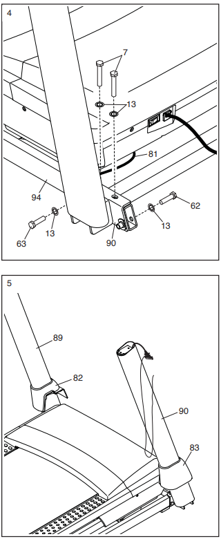
- Identify the left handrail assembly (E). Attach the left handrail assembly to the Left Upright (89) with two 5/16" x 2 1/2" Screws (28) and two 5/16" Star Washers (11); do not fully tighten the Screws yet.
Then, remove and discard the indicated screw (F). Insert the Upright Wire (81) into the bottom of the right handrail assembly (G) and out of the front as shown.
Attach the right handrail assembly (G) to the Right Upright (90) with two 5/16" x 2 1/2" Screws (28) and two 5/16" Star Washers (11). Make sure not to pinch the Upright Wire (81); do not fully tighten the Screws yet.
Then, remove and discard the indicated screw (F).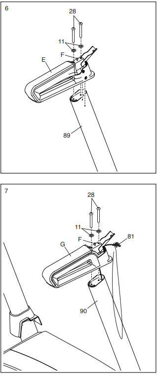
- ighten four #8 x 3/4" Screws (2) into the left and right handrail assemblies (E, G) and into the Left and Right Uprights (89, 90).
Set the Console Base (64) face down on a soft surface to avoid scratching the Console Base. If there are ties (H) securing the Pulse Crossbar
(93) to the Console Base, remove the ties.
Remove and discard the four indicated screws (I). Then, remove the Pulse Crossbar (93).
Remove and save the four 5/16" x 3/4" Screws (4) and six #8 x 3/4" Screws (2). Then, lift out the two Console Clamps (92) and the Console Frame (18).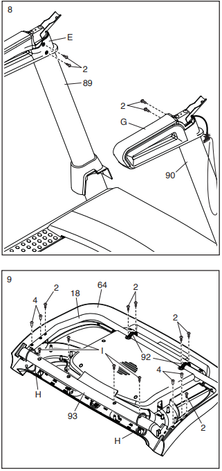
- Identify the Right and Left Trays (27, 36).
Attach the Trays (27, 36) to the Console Base (64) with eight #8 x 1/2" Screws (1); do not overtighten the Screws.
Reattach the Console Frame (18) with the
six #8 x 3/4" Screws (2) and the two Console Clamps (92) that you removed in step 9; do not overtighten the Screws. IMPORTANT: To avoid damaging the Pulse Crossbar (93), do not use power tools and do not overtighten the #10 x 3/4" Screws (9).
Orient the Pulse Crossbar (93) as shown. Attach the Pulse Crossbar to the Handrails (86) with two #10 x 3/4" Screws (9) and two #10 Star Washers (5); start both Screws, and then tighten them.
Make sure not to pinch the Upright Wire (81). Firmly tighten the four 5/16" x 2 1/2" Screws (28).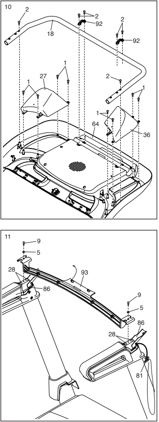
- With the help of a second person, hold the con- sole assembly (J) near the Handrails (86) (only one side is shown).
Connect the ground wire (K) from the console assembly (J) to the Console Ground Wire (58) on the Pulse Crossbar (93).
See the inset drawing. Connect the Upright Wire (81) to the console wire (L). The connec-tors should slide together easily and snap into place. If they do not, turn one connector and try again. IF YOU DO NOT CONNECT THE CONNECTORS PROPERLY, THE CONSOLE MAY BECOME DAMAGED WHEN YOU TURN ON THE POWER. Then, remove the wire tie (A) from the Upright Wire. Set the console assembly (J) on the brackets on the Handrails (86). Make sure not to pinch any wires.
Attach the console assembly (J) to the brackets on the Handrails (86) with the four 5/16" x 3/4" Screws (4) that you removed in step 9 and four 5/16" Star Washers (11); do not fully tighten the Screws yet.
Insert the excess Upright Wire (81) into the Right Upright (90).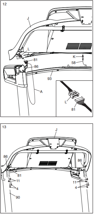
- Attach the Pulse Crossbar (93) to the console assembly (J) with four #8 x 1/2" Screws (1); start all four Screws, and then tighten them.
Then, firmly tighten the four 5/16" x 3/4" Screws (4). Raise the Frame (56) to the upright position.
Have a second person hold the Frame until step 17 is completed.
Remove the two 5/16" x 3/4" Screws (4) from the Latch Crossbar (41).
Orient the Latch Crossbar (41) as shown. Make sure that the “This side toward belt” sticker (M) is facing the treadmill. Attach the Latch Crossbar to the brackets (N) on the Frame (56) with two 5/16" x 3/4" Screws (4) that you just removed and two 5/16" Star Washers (11).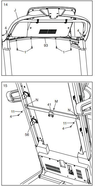
- Remove the 5/16" Nut (34) and the 5/16" x 1 3/4" Bolt (6) from the bracket on the Base (94).
Next, orient the Storage Latch (53) as shown.
Attach the lower end of the Storage Latch (53) to the bracket on the Base (94) with the 5/16" x 1 3/4" Bolt (6) and the 5/16" Nut (34) as shown.
Then, raise the Storage Latch (53) to a vertical position, and remove the tie (O). Remove the 5/16" Nut (34) and the 5/16" x 2 1/4" Bolt (3) from the bracket on the Latch Crossbar (41).
Align the upper end of the Storage Latch (53) with the bracket on the Latch Crossbar (41), and insert the 5/16" x 2 1/4" Bolt (3) through the bracket and the Storage Latch. This will push a spacer (P) out of the Storage Latch; discard the spacer.
Next, tighten the 5/16" Nut (34) onto the 5/16" x 2 1/4" Bolt (3). Do not overtighten the Nut; the Storage Latch (53) must be able to pivot.
Then, lower the Frame (56) (see HOW TO LOWER THE TREADMILL FOR USE on page 27).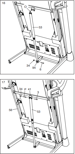
- Firmly tighten the four 3/8" x 2 3/8" Screws (7), the two 3/8" x 1 3/4" Screws (62), and the two 3/8" x 1 1/4" Screws (63).
Next, set the Left Inner Base Cover (99) onto the lower end of the Left Upright (89). Slide the Left Base Cover (82) downward and press it onto the Left Inner Base Cover.
Then, set the Right Inner Base Cover (31) onto the lower end of the Right Upright (90). Slide the Right Base Cover (83) downward and press it onto the Right Inner Base Cover. Press the two tabs on the Tablet Holder (98) into the slots (Q) in the console assembly (J).
Attach the Tablet Holder (98) with four #8 x 5/8" Machine Screws (38).
Note: Start the two top Machine Screws fi rst, and then start the two bottom Machine Screws. Be careful not to overtighten the Machine Screws.
IMPORTANT: The Tablet Holder (98) is designed for use with most full-size tablets. Do not place any other electronic device or object in the Tablet Holder.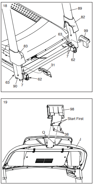
- Make sure that all parts are properly tightened before you use the treadmill. If there are sheets of plastic on the treadmill decals, remove the plastic. To protect the floor or carpet, place a mat under the treadmill. To avoid damage to the console, keep the treadmill out of direct sunlight. Keep the included hex key in a secure place; the hex key is used to adjust the walking belt (see pages 29 and 30).
Note: Extra hardware may be included.
HOW TO FOLD AND MOVE THE TREADMILL
HOW TO FOLD THE TREADMILL
To avoid damaging the treadmill, adjust the incline to zero before you fold the treadmill. Then, remove the key and unplug the power cord.
CAUTION: You must be able to safely lift 45 lbs. (20 kg) to raise, lower, or move the treadmill.
- Hold the metal frame fi rmly in the location shown by the arrow below.
CAUTION: Do not hold the frame by the plastic foot rails. Bend your legs and keep your back straight. Raise the frame until the storage latch locks in the storage position.
CAUTION: Make sure that the storage latch locks.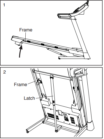
To protect the fl oor or carpet, place a mat under the treadmill. Keep the treadmill out of direct sunlight. Do not leave the treadmill in the storage position in tem-peratures above 85°F (30°C).
HOW TO MOVE THE TREADMILL
Before moving the treadmill, fold it as described at the left.
CAUTION: Make sure that the latch knob is locked in the storage position. Moving the treadmill may require two people.
Hold the frame and one of the handrails, and place one foot against a wheel.
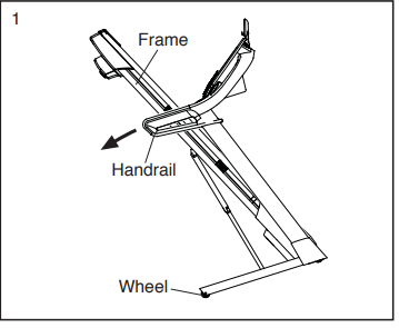
- Pull back on the handrail until the treadmill will roll on the wheels, and carefully move it to the desired location.
CAUTION: Do not move the tread-mill without tipping it back, do not pull on the frame, and do not move the treadmill over an uneven surface.
HOW TO LOWER THE TREADMILL FOR USE
- Push the upper end of the frame forward, and gently press the upper part of the storage latch with your foot at the same time.
While pressing the storage latch with your foot, pull the upper end of the frame toward yourself.
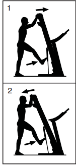
- Step back and let the frame lower to the floor.
Setup Guide
Setting up the NordicTrack C700 Treadmill involves several straightforward steps:
- Unpack the treadmill carefully from its packaging and ensure all parts are included.
- Assemble the frame according to the provided instructions. This typically involves attaching the side rails, console, and other components.
- Plug in the treadmill and turn it on. Follow the on-screen instructions to configure your settings such as language, units of measurement (e.g., miles vs kilometers), and user profiles.
- Pair your device with Bluetooth if you plan to use iFit or other compatible apps. Download and install any necessary software from NordicTrack's official website.
MAINTENANCE
- Regular maintenance is important for optimal per-formance and to reduce wear.
- Inspect and properly tighten all parts each time the treadmill is used. Replace any worn parts immediately.
- Regularly clean the treadmill and keep the walking belt clean and dry. First, press the power switch into the off position and unplug the power cord.
- Wipe exte-rior parts of the treadmill with a damp cloth and a small amount of mild soap.
IMPORTANT: Do not spray liquids directly onto the treadmill. To avoid damage to the console, keep liquids away from the console. Then, thoroughly dry the treadmill with a soft towel.
TROUBLESHOOTING
Most treadmill problems can be solved by follow-ing the simple steps below. Find the symptom that applies, and follow the steps listed. If further assis-tance is needed, see the front cover of this manual.
SYMPTOM: The power does not turn on
- Make sure that the power cord is plugged into a surge suppressor and that the surge suppressor is plugged into a properly grounded outlet (see page 18). Use only a surge suppressor that meets
all of the specifi cations described on page 18.
IMPORTANT: If the treadmill is connected to an AFCI-equipped outlet and your circuit breaker trips repeatedly when the treadmill is used, see the front cover of this manual to purchase an arc fi lter. - After the power cord has been plugged in, make sure that the key is inserted into the console.
Check the power switch located on the treadmill frame near the power cord. If the switch protrudes as shown, the switch has tripped. To reset the power switch, wait for five minutes and then press the switch back in.

SYMPTOM: The power turns off during use
- Check the power switch (see the drawing above). If the switch has tripped, wait for five minutes and then press the switch back in.
- Make sure that the power cord is plugged in. If the power cord is plugged in, unplug it, wait for five minutes, and then plug it back in.
- Remove the key from the console, and then reinsert it.
- If the treadmill still will not run, please see the front cover of this manual.
SYMPTOM: The incline of the treadmill does not change correctly
- Hold down the Stop button and the Speed increase button, insert the key into the console, and then release the Stop button and the Speed increase button. Next, press the Stop button and then press the Incline increase or decrease button. The treadmill will automatically rise to the maximum incline level and then return to the minimum level. This will recalibrate the incline system. If the incline system does not begin calibrating, press the Stop button again, and then press the Incline increase or decrease button again. When the incline system is calibrated, remove the key from the console.
SYMPTOM: The walking belt slows when walked on
- Use only a surge suppressor that meets all of the specifi cations described on page 18.
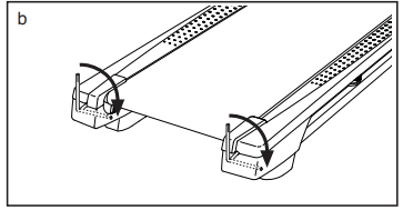
If the walking belt is overtightened, treadmill performance may decrease and the walking belt may become damaged. Remove the key and UNPLUG THE POWER CORD. Using the hex key, turn both idler roller screws counterclockwise, 1/4 of a turn. When the walking belt is properly tightened, you should be able to lift each edge of the walking belt 2 to 3 in. (5 to 7 cm) off the walking platform. Be careful to keep the walking belt centered. Then, plug in the power cord, insert the key, and walk on the treadmill for a few minutes. Repeat until the walking belt is properly tightened.
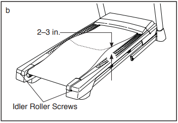
- Your treadmill features a walking belt coated with high-performance lubricant.
IMPORTANT: Never apply silicone spray or other substances to the walking belt or the walking platform unless instructed to do so by an authorized service representative. Such substances may deteriorate the walking belt and cause excessive wear. If you suspect that the walking belt needs more lubricant, see the front cover of this manual. - If the walking belt still slows when walked on, see the front cover of this manual.
SYMPTOM: The walking belt is off-center or slips when walked on
If the walking belt is off-center, first remove the key and UNPLUG THE POWER CORD. If the walking belt has shifted to the left, use the hex key to turn the left idler roller screw clockwise 1/2 of a turn; if the walking belt has shifted to the right, turn the left idler roller screw counterclockwise 1/2 of a turn. Be careful not to overtighten the walking belt. Then, plug in the power cord, insert the key, and walk on the treadmill for a few minutes. Repeat until the walking belt is centered.
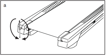
If the walking belt slips when walking on, first remove the key and UNPLUG THE POWER CORD. Using the hex key, turn both idler roller screws clockwise, 1/4 of a turn. When the walking belt is correctly tightened, you should be able to lift each edge of the walking belt 2 to 3 in. (5 to 7 cm) off the walking platform. Be careful to keep the walking belt centered. Then, plug in the power cord, insert the key, and walk on the treadmill for a few minutes. Repeat until the walking belt is properly tightened.
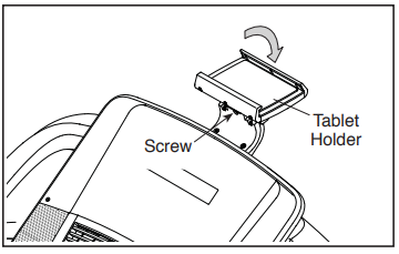
SYMPTOM: The tablet holder does not stay in place
Rotate the tablet holder backward. Then, tighten the indicated screw slightly until the tablet holder stays in place when it is rotated to the desired position.
Pros & Cons
Pros
- Equipped with iFit compatibility, Bluetooth connectivity, and a large HD touchscreen display.
- Built with a sturdy frame and powerful motor ensuring long-lasting performance.
- Spacious running deck and heart rate monitoring features enhance user comfort.
- Supports various workout types including walking, jogging, running, and incline training.
Cons
- While competitively priced within its category, it may still be out of budget for some consumers.
- The folding design helps, but it still requires significant space when in use.
- Some users may find assembly challenging without professional help
Customer Reviews
Customer reviews highlight the NordicTrack C700 Treadmill's effectiveness in meeting fitness goals while praising its durability and user-friendly interface:
- "This treadmill has been a game-changer for my home workouts. The iFit integration is seamless and the variety of programs keeps me motivated." - Sarah R.
- "I was skeptical about buying a treadmill online but this one exceeded my expectations. Easy setup and great value for money!" - John D.
Common complaints include minor issues with assembly and occasional connectivity problems with iFit which are typically resolved through customer support.
NordicTrack C700 Treadmill Warranty
ICON Health & Fitness, Inc. (ICON) warrants this product to be free from defects in workmanship and material, under normal use and service conditions. The frame is warranted for the lifetime of the original purchaser (customer). The motor is warranted for twenty-fi ve (25) years from the date of purchase. Parts and labor are warranted for one (1) year from the date of purchase.
Faqs
What is the maximum weight capacity of the NordicTrack?
How do I assemble the C700 Treadmill?
Is the NordicTrack Treadmill compatible with iFit?
What is the size of the running deck on the Treadmill?
What kind of motor does the NordicTrack C700 Treadmill have?
Does the Treadmill come with heart rate monitoring?
What are some common complaints about the NordicTrack C700 Treadmill?
Leave a Comment
