Pioneer Central Split Air Conditioner YH024GHF User Manual
Content
Air Conditioner YH024GHF Introduction
The Pioneer Central Split Air Conditioner YH024GHF is a powerful and efficient cooling solution designed to provide optimal comfort in residential and commercial spaces. With a cooling capacity of 24,000 BTUs, this unit effectively cools larger areas while maintaining energy efficiency with a Seasonal Energy Efficiency Ratio (SEER) of 18. Its sleek design and quiet operation make it a perfect addition to any environment. Priced at approximately $1,200, it offers an excellent balance of performance and value.
Features
- 360 DC inverter driven technology
With 360 all DC inverter driven technology, realize the compressor driving direction the same with rotary direction. Optimize energy-saving, and keep the compressor more stable and high efficient during operation. It can also guarantee more stable temperature control and reduce noise. - Pressure sensor
Inside the outdoor unit is the pressure sensor, which defects low pressure in cooling mode and high pressure in heating mode. The intelligent control can be realized by calculating the indoor coil temperature through the pressure valve. - Smaller outdoor dimension for installation flexibility
The side-discharge outdoor unit, saves roughly 36% more space than traditional air conditioners. More conveniently, it can be installed on wall, yard or on the roof. - Convenient Installation
The stop valve and connecting pipes are connected by welding, and indoor unit of other brands can freely be connected with this outdoor unit. - Comfortable temperature control
DC inverter power control uses its full capacity at startup to cool/warm quickly. As soon as the set temperature is reached, it carefully adjusts current frequency to prevent temperature fluctuation and energy loss.
Product lineup
Model (Btu/h)
Type |
24K |
36K |
60K |
Outdoor unit |
● |
● |
● |
●: available model
Unit installation
System is the only compatible combination.
(Only one indoor unit can be connected with one outdoor unit.)
Working range
Power Supply
Working Voltage | 198V ~ 253V |
Voltage Imbalance | Within a 3% deviation fromeach voltage at the mainterminal of outdoorunit |
Starting Voltage | Higher than 85%of the Rated Voltage |
Operating temperature range
This air conditioner is designed for the following outdoor operating temperatures.
Type | Mode | Outdoor operating temperature | |
maximum | minimum | ||
DC-Inverter Split Air Conditioner (Heat pumptype) | Cooling Operation | 114.8℉ (46℃) | 5℉ (-15℃) |
Heating Operation | 75℉ (24℃) | -13℉ (-25℃) | |
Storage condition
- Temperature: -13℉~140℉ (-25℃~60℃)
- Humidity: 30%~80%
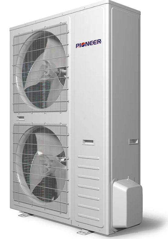
Product Appearance
Model (Btu/h) |
Outdoor Unit |
24K |
|
Air Conditioner Specifications
| Parameter | Value |
|---|---|
| Model | YH024GHFI18RT2 |
| Rated Current (RLA) | 9.45 A |
| Compressor | VG74 1670 |
| Refrigerant Oil Type | VG74 / 22.7 |
| Refrigerant Type | R-410A |
| Refrigerant Quantity | 2 oz. |
| Refrigerant Charge | 70.5 oz. |
| Factory Precharge | 25 oz. |
| Additional Charge for Each Ft. | $9.52 (3/8') |
| Liquid Line OD | Ф15.88 (5/8') |
| Vapor Line OD | Ф15.88 (5/8') |
| Refrigerant Piping Max. Length | 50 m |
| Max. Difference in Level | 30 m |
| Parameter | Value |
|---|---|
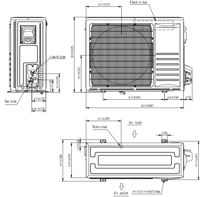
| Dimension (W × H × D) | 860 × 670 × 310 mm |
| 33.7 × 26.3/8 × 12.25 in | |
| Packing (W × H × D) | 990 × 730 × 450 mm |
| 39 × 28.75 × 17.75 in | |
| Outdoor Unit Net Weight | 51 kg |
| 112.4 lbs | |
| Shipping Weight | 55 kg |
| 121.3 lbs | |
| Qty per 20' / 40' / 40'HQ | 90 / 186 / 186 sets |
NOTE:
- Test conditions:
- Rated capacity test conditions:
- Cooling:
- Indoor: DB 80.0°F (26.7 C) WB 67.0°F (19.4 C)
- Outdoor: DB 95.0°F (35.0 C) /WB 75.0°F (23.9 C)
- Heating:
- Indoor: DB 70.0°F (21.1 C) /WB 60.0°F (15.6 C)
- Outdoor: DB 47°F (8.3 C) /WB 43°F (6.1 C)
- Cooling:
- SEER & HSPF test standard: AHRI 210/240.
- Rated capacity test conditions:
- The Sound Pressure Level is based on the following conditions:
- Outdoor unit:
Measure the noise value of 3 points, which are1 meter in front of the three sides of the unit surface (front/left/right) and 1/2(unit height +1) meter high from floor level, and calculate the weighted average of the noise.
- Outdoor unit:
- The above data was measured in an anechoic chamber. Please take into consideration the reflected sound of your specific application environment.
- All specifications are subjected to change by the manufacturer without prior notice.
Outlines and dimensions
24K
Description
The Pioneer Central Split Air Conditioner YH024GHF boasts advanced inverter technology that allows for precise temperature control and significant energy savings. The system includes both an indoor and outdoor unit, ensuring a quiet and efficient operation. The indoor unit features a sleek design that blends seamlessly into any decor, while the outdoor unit is built to withstand various weather conditions.
The air conditioner also includes a built-in air filter that helps purify the air, improving indoor air quality. Additionally, it offers multiple operation modes, including a dehumidification mode, to cater to different climate needs.
Electrical data
Outdoor unit |
Power supply |
Applicable voltage |
ELB | ||||
Voltage(V) |
PH |
Frequency (Hz) |
Umin (V) |
Umax (V) |
Nominal Current (A) | Nominal Sensitive Current (mA) | |
24K |
208/230 |
1 |
60 |
198 |
253 |
25 |
30 |
36K |
208/230 |
1 |
60 |
198 |
253 |
35 |
30 |
60K |
208/230 |
1 |
60 |
198 |
253 |
60 |
30 |
NOTE:
- The above compressor data is based on 100% capacity combination of indoor units at the rated operating frequency.
- This data is based on the same conditions as the nominal heating and cooling capacities.
- The compressor started by an inverter, resulting in extremely low starting current.
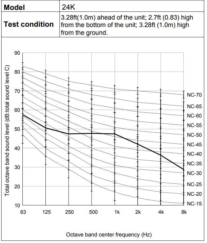
Sound pressure data
Outdoor unit
Refrigerant cycle
Outdoor unit
24K
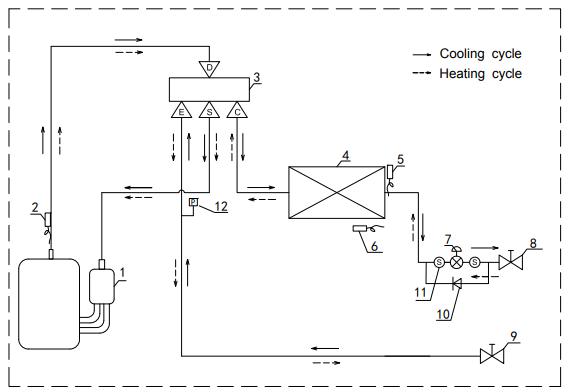
List of components | |||
1 | Compressor | 7 | Electronic expansion valve |
2 | Discharge temperature sensor | 8 | Stop valve (Liquid) |
3 | 4-Way valve | 9 | Stopv valve (Gas) |
4 | Outdoor heat exchanger | 10 | One-way valve |
5 | Coil temperature sensor | 11 | Strainer |
6 | Ambient temperature sensor | 12 | Pressure sensor |
Setup Guide
To operate the Pioneer Central Split Air Conditioner YH024GHF,
- Start by ensuring both the indoor and outdoor units are properly installed by a certified technician.
- Once installed, turn on the power and use the remote control to set your desired temperature and mode.
- For assembly and configuration, follow the manufacturer's instructions carefully.
- Pairing with smart home systems can be done through the manufacturer's app, which allows for remote control and scheduling of cooling cycles.
Piping work and refrigerant charge
MAX.length allowed
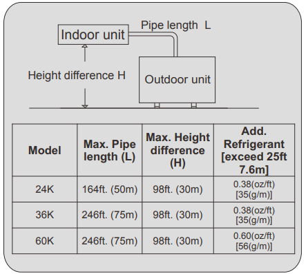
Additional refrigerant charge
24K/36K: Additional refrigerant charge= (L-25) ft×0.38 oz/ft 60K: Additional refrigerant charge= (L-25) ft×0.60 oz/ft
Model |
Refrigerant precharged before shipment (oz.) | Total refrigerant pipe length | |
0ft.~25ft. | Long than 25ft. | ||
24K | 70.5 | 0 | Xg = 0.38oz/ft ×(Total pipe length(ft.) -25) |
36K | 98.7 | 0 | Xg = 0.38oz/ft ×(Total pipe length(ft.) -25) |
60K |
142.9 | 0 | Xg = 0.60oz/ft ×(Total pipe length(ft.) -25) |
Oil trap
When the indoor unit is lower than outdoor unit and height difference is larger than 5m, set an oil trap every 5m (height difference) on suction piping.
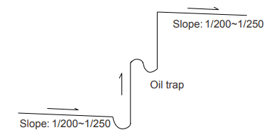
NOTE:
- To avoid storing too much oil in the oil trap, the oil trap should be as short as possible.
- The horizontal piping should slope down along the refrigerant flow direction, to bring the oil back to compressor, the slope is about 1/200 to1/250.
- In order to ensure cooling/heating performance better, the refrigerant piping should be as short and straight as possible.
Air tight test
- Do use nitrogen when performing air-tight test.
Connect the gauge manifold using charging hoses with a nitrogen cylinder to the check joints of the liquid line and the gas line stop valves. Perform the air-tight test. Don't open the gas line stop valves. Apply nitrogen gas pressure of 550 psig (3.8MPa). Check for any gas leakage at the flare nut connections, or brazed parts by gas leak detector or foaming agent. It is OK if gas pressure does not decrease. After the air tight test, release nitrogen gas.
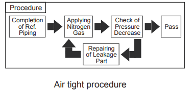
Additional refrigerant charge
Although refrigerant has been charged into this unit, additional refrigerant charge is required according to the piping length.
- The additional refrigerant precharge quantity should be determined and charged into the system according to the following procedure.
- Record the additional refrigerant quantity in order to facilitate maintenance and servicing activities. Refrigerant charge before shipment (W0 (oz.))
W0 is the outdoor unit refrigerant charge before shipment; Xg is additional refrigerant outdoor unit needed to charge according to piping length during installation.
Troubleshooting
Troubleshooting for normal malfunction
Troubleshooting | Possible Reasons of Abnormality | How to Deal With |
Air conditioner cannot start up |
|
|
The compressor starts or stops frequently | The air inletand outlet has been blocked. | Remove block obstacles. |
Poor cooling/heating |
|
|
Sound from deforming parts |
During systemstarting or stopping, a sound might be heard. However, this is due to thermal deformation of plastic parts. |
It is not abnormal, and the soundwill disappear soon. |
Water leakage |
|
|
Troubleshooting according to fault codes
When the air conditioner failure occurs, the fault code will display on the control board.
How to check fault codes
Outdoor unit
24K
DC-Inverter unitary (Main control board upside-down)
.png)
- Fault code displayed by LED lamps on outdoor main control board.
- There are 3 LED lamps on control board, LED1, LED2 and LED3.
- LED1 indicates fault code represented by 2-digit number,
- LED2 indicates fault code represented by single digit number,
- LED3 indicates outdoor drive control fault.
- When LED3 is off, LED1 and LED 2 indicate main control fault code.
- When LED3 is on, LED1 and LED 2 indicate drive control fault code.
- When LED3 is flickering and LED1, LED 2 are all off, it indicates the compressor is preheating. Failures display with 5s interval. It means LED will be off for 5s to report the next fault code. System protection codes display method is the same with main control fault code.
- LED lamps will be off when there is no failure, protection or preheating.
For example, outdoor main control fault 32:

For example, outdoor drive fault 32:
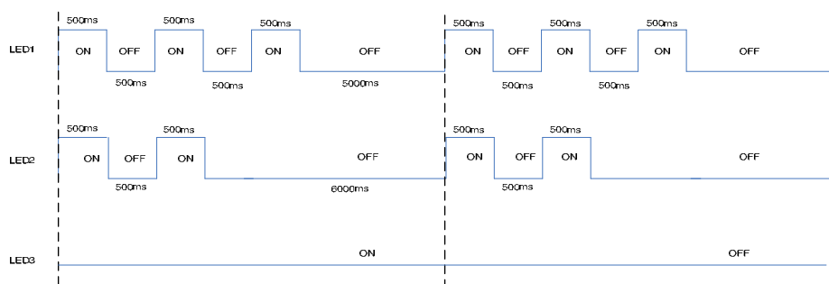
Fault codes
The following is the fault code table of outdoor units.
Fault code | Fault description | Possible reasons for abnormality | How to deal with | Remarks |
1 |
Outdoor ambient temperature sensor fault |
|
| |
2 |
Outdoor coil temperature sensor fault |
1.The outdoor coiltemperature sensor is connected loosely; 2.The outdoor coil temperature sensor fails to work; 3.The sampling circuitfails. |
| |
3 |
The unitover-current turn off fault |
circuit fails;
|
| |
4 |
EEprom Dataerror |
| 1.Replace the EE components; 2.Replace the outdoor control board components; 3.Reassemble the EE components. | |
5 |
Cooling freezing protection (the indoor coil temperature is too low) or heating overload (indoor coil temperature is too high) |
standards, andthe air inletis too close to the air outlet . |
referring to the usermanual to change the distance between the indoor unit and the wall or ceiling. | |
7 |
The communication fault between the indoor unit and outdoor unit |
communication cable is incorrect. |
referring to the user manual. |
13 |
Compressor overheat protector device |
|
| |
14 |
The high pressure switch operation or the unit is turned off for high pressure protection |
|
| Applied to models with high pressure switch or pressure sensor |
15 |
The low pressure switch protection or theunit is turnedoff for low pressure protection |
|
|
Applied to models with low pressure switch or pressure sensor |
16 | Overload protection in cooling mode | System overload | Please referto NOTE 3. | |
17 |
Discharge temperature sensor fault |
tempe-rature sensoris connected loosely;
|
| |
18 | AC voltage is abnormal |
|
| |
19 |
Suction temperature sensor fault |
|
| |
22 |
The defrosting sensor fault |
|
| |
43 |
High Pressure sensor fault |
pressure pressure sensorfails. |
|
45 |
IPM fault | There are many reasons for this failure. You can check the driver board fault LED to further analyze the faultcode of the drive boardand to learn aboutwhat leads to the fault and how to operate it. Specific information can be seen in table 5, table 6. |
See attached "analysis of the driving board fault". |
46 |
IPM and control board communication fault |
|
|
47 |
Too highdischarge temperature fault |
|
|
48 |
The outdoor DC fan motor fault (upper fan motor) |
motor fails;
|
fan motor; 5.Check the outdoor fan and ensure the outdoor fan can run normally. |
49 |
The outdoor DC fan motor fault (down fan motor) |
1.The connecting wiring of the down DC fan motor is loose; 2.The cord of the downDC fan motor fails;
|
|
91 |
The unitturn off due to the IPM board overheating fault |
motor is too low if the fan motor is AC fan motor;
|
|
96 | Lacking of refrigerant | The refrigerant of the unitis not enough. | Discharge the refrigerant and charge the refrigerant referring to the rating label. |
97 |
4-way valve commutation failure fault |
4.The driverboard of the 4-way valve fails. |
|
NOTE 1:
If the indoor unit can not start or the indoor unit stops itself after 30s, at the same time the unit does not display the fault code, please check the fire and the socket of the control board.
NOTE 2:
If the indoor unit displays the 75,76,77,78 fault code after you turn on the unit, please check the TEST seat of the indoor control board or the TEST detection circuit to see whether short circuit occurs.
NOTE 3: Overload in cooling mode
Table 2 Drive fault code (24K)
Overload in coolingmode | ||
sr. | The root cause | Corrective measure |
1 |
The refrigerant is excessive. | Discharge the refrigerant, and recharge the refrigerantreferring to therating label. |
2 | The outdoor ambient temperature is too high. | Please use withinallowable temperature range |
3 | Short-circuit occurs in the air outlet and air inletof the outdoor unit. | Adjust the installation of the outdoor unit referring to the user manual. |
4 | The outdoor heat exchanger is dirty, such as condenser. | Clean the heat exchanger of the outdoor unit, such as condenser. |
5 | The speed of the outdoor fan motor is too low. | Check the outdoor fan motor and fan capacitor. |
6 | The outdoor fan is brokenor the outdoor fan is blocked. |
Check the outdoor fan. |
7 | The air inlet and outlet has beenblocked. | Remove the obstructions. |
8 | The expansion valveor the capillary fails. | Replace the expansion valve or the capillary. |
NOTE 4: Over load in heating mode
Overload in heating mode | ||
sr. | The root cause | Corrective measures |
1 |
The refrigerant is excessive. | Discharge the refrigerant, and recharge the refrigerantreferring to the rating label. |
2 | The indoor ambienttemperature is too high. | Please use it within allowable temperature range. |
3 | Short-circuit occurs in the air outlet and air inlet of theindoor unit. | Adjust the installation of the indoor unit referring to the user manual. |
4 | The indoor filter is dirty. | Clean the indoor filter. |
5 | The speed of the indoor fan motor is too low. | Check the indoor fan motor and fan capacitor. |
6 | The indoor fan is brokenor the outdoor fan is blocked. |
Check the indoor fan. |
7 | The air inlet and outlet has beenblocked. | Remove the obstructions. |
8 | The expansion valveor the capillary fails. | Replace the expansion valve or the capillary. |
Table 2 Drive fault code (24K)
Fault code | Fault description | Possible reasons for abnormality | How to deal with |
1 | Inverter DC voltageoverload fault |
|
|
2 | Inverter DC low voltage fault | ||
3 | Inverter AC currentoverload fault | ||
4 | Out-of-step detection |
|
|
5 | Loss phasedetection fault (speed pulsation) | ||
6 | Loss phasedetection fault (current imbalance) | ||
7 | Inverter IPM fault (edge) |
|
|
8 | Inverter IPM fault (level) | ||
9 | PFC_IPM IPM fault (edge) | ||
10 | PFC_IPM IPM fault (level) | ||
11 |
PFC power detection of failure |
|
|
12 |
PFC overload current detection of failure. |
| 1.Check the system; 2.Change the driverboard; 3.Change the PFC. |
13 | DC voltage detected abnormal . |
|
|
14 | PFC LOW voltagedetected failure. | ||
15 | AD offset abnormaldetected failure. |
Driver board fails. |
Change the driverboard. |
16 | Inverter PWM logic set fault. | ||
17 | Inverter PWMinitialization failure | ||
18 | PFC_PWM logicset fault. | ||
19 | PFC_PWM initialization fault. | ||
20 | Temperature abnormal. | ||
21 | Shunt resistance unbalance adjustment fault | ||
22 |
Communication failure. |
|
|
23 | Motor parameters setting of failure | Initialization is abnormal. | Reset the power supply. |
26 |
DC voltage mutation error |
|
|
27 |
D axis currentcontrol error |
|
|
28 |
Q axis currentcontrol error |
|
|
29 |
Saturation errorof d axis current control integral |
|
|
30 |
Saturation errorof q axis current control integral |
|
|
35 | EE data abnormal | Driver board EEPROMis abnormal |
|
Pioneer Central Split Air Conditioner YH024GHF Pros & Cons
Pros:
- High energy efficiency with SEER rating of 22
- Advanced inverter technology for precise temperature control
- Quiet operation with noise levels as low as 40 dB
- Built-in air purification system
- Smart home compatibility for remote control and scheduling
- Multiple operation modes including dehumidification
Cons:
- Higher upfront cost compared to traditional AC units
- Requires professional installation
- May require additional components for smart home integration
- Larger outdoor unit may require more space
Customer Reviews
Customers have praised the Pioneer Central Split Air Conditioner YH024GHF for its efficient cooling and quiet operation. Many have noted significant savings on their energy bills. However, some users have reported higher installation costs and the need for professional setup.
Common complaints include the size of the outdoor unit and the complexity of smart home integration. Despite these, the overall satisfaction rate remains high due to the unit's performance and features.
Faqs
What is the cooling capacity of the Pioneer?
Is the Pioneer YH024GHF energy-efficient?
Does the Air Conditioner come with a remote control?
Can the Conditioner YH024GHF be integrated with smart home systems?
How noisy is the Pioneer YH024GHF?
Does the Air Conditioner YH024GHF have an air purification feature?
What maintenance is required for the Air Conditioner?
Can I install the Pioneer YH024GHF myself?
What are the common issues with the Pioneer Central?
Is there a warranty on the Air Conditioner?
Leave a Comment

