Powertec Trim Router Table 71392 User Manual | Assembling & Installing
Content
Powertec Trim Router Table 71392 Manual: A Comprehensive Guide
The Powertec Trim Router Table 71392 is a versatile and durable addition to any woodworking shop. This router table is designed to provide a stable and accurate platform for your router, allowing you to make precise cuts and finishings on your woodworking projects. With an estimated price range of $150 to $200, this router table offers great value for its features and performance. Although the official launching date is not yet announced, it is already generating buzz in the woodworking community.
Detailed Specifications
The Powertec Trim Router Table 71392 Manual boasts several key features that make it a great choice for woodworkers. Here are some of its specifications:
- Durable and stable construction with aluminum router mounting plate and steel stand
- Adjustable fence with dual-locking levers for precise and secure positioning
- 2.25-inch dust collection port for easy cleanup
- Compatible with most routers up to 3-1/2 horsepower
- Level-loc reducing rings for quick and easy bit changes
- Pre-drilled mounting holes for easy installation
- Spacious work surface for larger workpieces
- Weight: 33 pounds
- Dimensions: 23.5 x 16 x 16.5 inches
ASSEMBLY
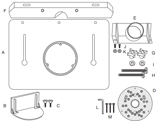
Included Parts Powertec Trim Router Table 71392
Check for shipping damage. Check immediately whether all parts and accessories are included.
| ITEM | DESCRIPTION | QTY |
|---|---|---|
| A | Router table top | 1 |
| B | Bit guard | 1 |
| C | Bit guard knobs | 2 |
| D | Universal trim router base (Powertec 71381) | 1 |
| E | Router dust port (Powertec 70152) | 1 |
| F | Router table fence | 1 |
| G | Fence lock knobs | 2 |
| H | T-Bolts 5/16"-18 x 4" | 2 |
| I | Washers 5/16" | 2 |
| J | M4 x 10 mm pan head screws | 2 |
| K | Washers 1/4" | 2 |
| L | Hex wrench 3 mm | 1 |
| M | Leveling screws 1" (hex head) | 3 |
UNPACKING
Figure 1
WARNING
Do not use the trim router table until it is completely assembled and you have read and understood this entire operating manual and the operating manual of the tool being used with this trim router table.
MOUNTING INSTRUCTIONS
ASSEMBLE FENCE, DUST PORT AND TABLE
Powertec Trim Router Table 71392
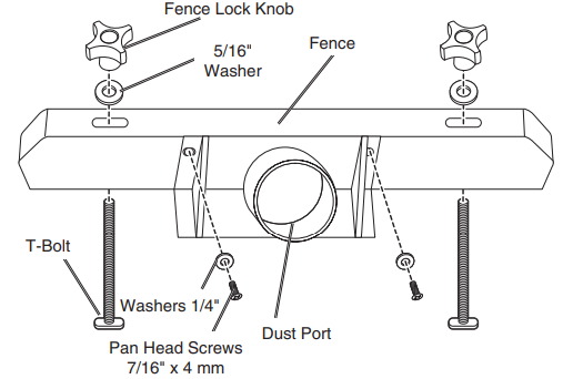
- From the underside of the fence, insert the two T-Bolts up and through the holes on each end the fence. Place a 5/16" washer on each T-Bolt and then thread on the fence lock knobs. Do not tighten the knobs.
Attach the Powertec 70152 dust port to the back of the fence using the pan head screws and 1/4" washers. Figure 2
Optional mounting: The trim router table may be attached to a longer board or cleat for clamping to a stationary work surface. If using this method, add the cleat now. There are pre-drilled cleat mounting holes at the rear of the trim router table. Drive #8 screws through the three cleat mounting holes and into the cleat.
NOTE: The screw length should be the thickness of the trim router table plus the cleat) Figure 3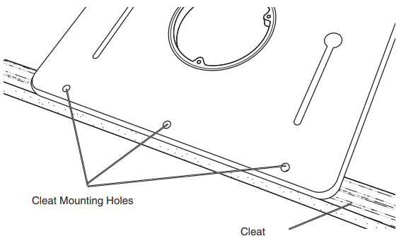
Install the fence to the table. Make sure the T-Bolt heads extend down far enough to fit into the fence adjustment slots in the table. Insert the T-Bolt heads into the round access holes in the tabletop, engage the heads in the stepped slots on the underside of the table and slide the fence toward the back.
NOTE: To adjust the fence, loosen the knobs, slide the fence to the desired application and tighten knobs. Figure 4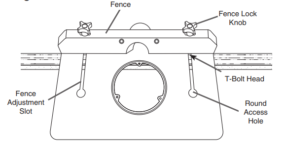
WARNING: The trim router table MUST be clamped or attached directly to a stationary work surface BEFORE operating the router. Figure 5 shows the trim router table with cleat clamped to a stationary work surface.
- Clamp or Attach the Table to Stationary Work Surface:
- If the cleat was assembled earlier, clamp it to the edge of a bench, table, piece of plywood or other stationary work surface.
The table may be attached directly to a stationary work surface. Drive #8 screws through the three cleat mounting holes and into the stationary work surface.
IMPORTANT: The screw length will be determined by the work surface thickness. The general rule is for the screw to enter at least half the thickness of the bottom material/work surface. Figure 5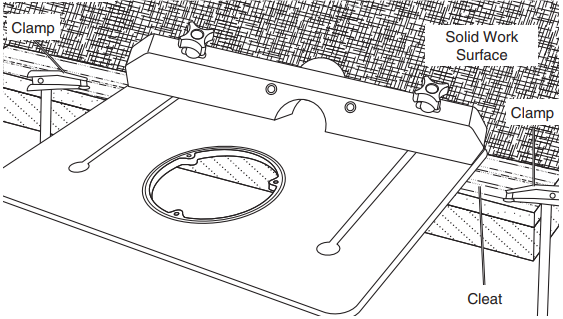
Install the three leveling screws from the bottom into the holes on the lip of the opening in the table.
NOTE: These screws are used to make the router base flush with the face of the tabletop. These screws will also register the three stopped holes in the underside of the trim router base to keep it from shifting during use. Figure 6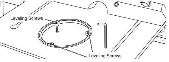
ASSEMBLY THE TRIM ROUTER BASE
WARNING: To reduce the risk of injury, turn router off and disconnect it from power source before installing and removing accessories. An accidental start-up can cause injury.
NOTE: This clear router plate provides better visibility and when used with a PORTER-CABLE style guide bushing (sold separately) it allows a bit to follow the path intended by a template or jig.
NOTE: The trim router base can be left on the router, allowing it to be taken from table routing to hand held routing without switching baseplates.
- Remove the existing router plate and all related hardware from the router.
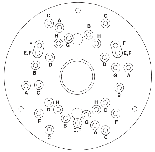
- On the chart find the model and the corresponding letter for your router.
Find the corresponding letters for your router in Figure 7.
NOTE: Some routers have more than one option.
- Place the universal router plate onto the router and line up the first letter with the appropriate hole and then rotate the plate until all holes for the pattern line up. Install and tighten the machine screws.
Figure 7
| Brand | Model | Type | Corresponding Letter |
|---|---|---|---|
| DeWALT* | DWP611PK | Fixed Base | A |
| DeWALT* | DWP611PK | Plunge Base | B |
| Makita* | RT0701CX7 | Plunge Base | C |
| Makita* | RT0701CX7 | Fixed Base | D |
| Bosch* | GKF125CEN | - | E |
| Bosch* | PR110 | - | F |
| Bosch* | PR10E/PR20EVS | - | F |
| Ryobi* | P601 | - | G |
| PORTER-CABLE* | PCE6435 | - | H |
INSTALLING ROUTER IN TABLE
- Loosen the fence locking knobs and slide the fence back on the tabletop to access the opening in the tabletop.
From the top of the table, lower the router with trim router base into the opening, align the three stopped holes on the underside of the router base with the three leveling screws. Figure 8
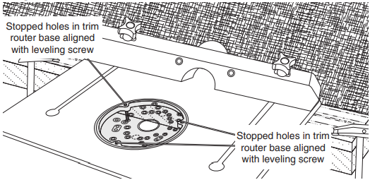
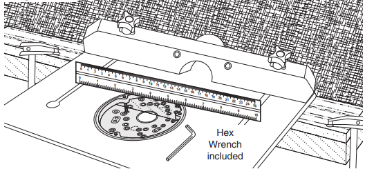
Use a straight edge to verify the trim router base is flush with the tabletop. If it is not flush, adjust the leveling screws until the router base plate is flush with the tabletop. Make sure the leveling screws are seated in the three stopped holes on the underside of the router base to prevent the base from shifting during use. Figure 9
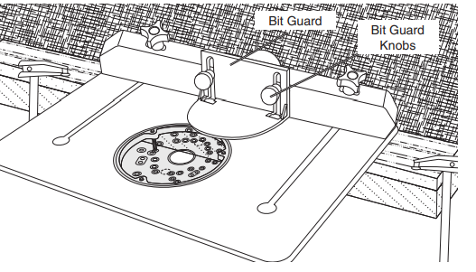
- Attach the bit guard to the front of the fence using the bit guard knobs.
NOTE: To adjust the bit guard, loosen the knobs, slide the bit guard up and down to desired application and tighten knobs. To temporarily remove the bit guard, slightly loosen the bit guard knobs and slide the guard up and over
the knobs. - Adjust the fence to the desired application and tighten the locking knobs.
Attach the dust extraction hose to the dust port. Figure 10
WARNING: The trim router table MUST be clamped in place or attached directly to a solid mounting surface BEFORE operating the router. Figure 5 shows the trim router table with cleat clamped into place.
MAINTENANCE
GENERAL MAINTENANCE
WARNING: When servicing, use only identical replacement parts. Use of any other parts may create a hazard or cause product damage. To ensure safety and reliability, all repairs should be performed by a qualified service technician.
WARNING: Keep the trim router table dry, clean, and free from oil and grease. Always use a clean cloth when cleaning. Never use brake fluids, gasoline, petroleum based products or any strong solvent to clean the trim router table. Chemicals can damage, weaken or destroy plastic which may result in serious personal injury.
Trim Router Base
Carnauba wax may be applied to the universal router plate to reduce scratching and make it slide easier. If scratching does occur, carefully polish with plastic polish until the scratches are removed.
SAFETY RULES
For your own safety, read all of the rules and precautions before operating tool Powertec Trim Router Table 71392.
WARNING
- Always follow proper operating procedures as defined in this manual even if you are familiar with use of this trim router table or any tool used with this trim router table. Remember that being careless for even a fraction of a second can result in severe personal injury.
- Before using another tool with this product, always read, understand and follow the instructions and safety warnings in the owner’s manual for that tool. If you do not have the owner’s manual, obtain one from the tool’s manufacturer before using it with this product.
- You must be familiar with the use of any tool or accessory used with this trim router table. The supplier cannot be held responsible for any accident, injury or damage incurred while using this trim router table with any tool.
- It is the purchaser of this product is responsible to ensure that any person using this product reads and complies with all instructions and safety precautions outlined in this manual prior to use.
CAUTION: Do not modify or use this trim router table for any application other than that for which it was designed.
FOLLOW ALL STANDARD SHOP SAFETY PRECAUTIONS, INCLUDING:
- Keep children and visitors at a safe distance from work area.
- Keep work area clean. Cluttered work areas invite accidents. Work area should be properly lit.
- Do not use power tools in dangerous environments. Do not use power tools in damp or wet locations. Do not expose power tools to rain.
- Wear proper apparel. Do not wear loose clothing, gloves, neckties, rings, bracelets or other jewelry which may get caught in moving parts of the tool.
- Wear protective hair covering to contain long hair.
- Wear safety shoes with non-slip soles.
- Wear safety glasses complying with United States ANSI Z87.1. Everyday glasses have only impact resistant lenses. They are NOT safety glasses.
- Wear face mask or dust mask if operation is dusty.
- Be alert and think clearly. Never operate power tools when tired, intoxicated or when taking medications that cause drowsiness.
- A guard or any other part that is damaged should be properly repaired or replaced. Do not perform makeshift repairs.
- Use the right tool for your job. Do not force your tool to do a job for which it was not designed.
- Use safety equipment such as featherboards, push sticks and push blocks, etc., when appropriate.
- Maintain proper footing at all times and do not overreach.
WARNING
- This trim router table MUST be clamped securely to a stationary support or attached to a cleat (using the pre-drilled cleat mounting holes) and clamped securely to a stationary support. Failure to properly secure the table could result in serious injury and property damage.
- To avoid serious injury, turn off and unplug the router before attaching the router base, changing accessories or adjusting the cutter height/fence position.
- Do not use the trim router table until it is completely assembled and you have read and understood this entire operating manual and the operating manual of the tool being used with this trim router table.
Product Description
The Powertec Trim Router Table 71392 Manual is a heavy-duty and reliable router table that is built to last. Its aluminum router mounting plate ensures a flat and stable surface for your router, while its steel stand provides stability and durability. The adjustable fence with dual-locking levers allows for precise and secure positioning, making it easy to make accurate cuts. The level-loc reducing rings make bit changes quick and easy, saving you time and effort. The 2.25-inch dust collection port ensures easy cleanup and a cleaner workspace. With its spacious work surface, this router table can accommodate larger workpieces, making it a versatile tool for any woodworking project.
WARRANTY
Thank you for investing in a POWERTEC power tool. This product has been designed and manufactured to meet high quality standards and is guaranteed for domestic use against defects in workmanship or material for a period of 12 months from the date of purchase. This guarantee does not affect your statutory rights. SOUTHERN TECHNOLOGIES LLC. BENCH TOP AND STATIONARY POWER TOOL LIMITED 1 YEAR WARRANTY AND 30-DAY SATISFACTION GUARANTEE POLICY POWERTEC products are designed and manufactured by Southern Technologies LLC. All warranty communications should be directed to Southern Technologies LLC by calling 847-780-6120, 9 AM to 5 PM, Monday through Friday, US Central Time.
30- DAY SATISFACTION GUARANTEE POLICY
During the first 30 days after the date of purchase, if you are dissatisfied with the performance of this POWERTEC tool for any reason, you may return the tool to the retailer from which it was purchased for a full refund or exchange. You must present proof of purchase and return all original equipment packaged with the original product. The replacement tool will be covered by the limited warranty for the balance of the one year warranty period.
ONE YEAR WARRANTY
This warranty covers all defects in workmanship or materials in this POWERTEC tool for a one year period from the date of purchase. This warranty is specific to this tool. Southern Technologies, LLC reserves the right to repair or replace the defective tool, at its discretion.
HOW TO OBTAIN SERVICE
To obtain service for this POWERTEC tool you must return it, freight prepaid, to POWERTEC. You may call 847-780-6120 for more information. When requesting warranty service, you must present the proof of purchase documentation, which includes a date of purchase. POWERTEC will either repair or replace any defective part, at our option at no charge to you. The repaired or replacement unit will be covered by the same limited warranty for the balance of one year warranty period.
WHAT IS NOT COVERED
This warranty applies to the original purchaser at retailer and may not be transferred. This warranty does not cover consumable items such as saw blades, knives, belts, discs, cooling blocks and sleeves. This warranty does not cover required service and part replacement resulting from normal wear and tear, including accessory wear. This warranty does not cover any malfunction, failure or defect resulting from:
- Misuse, abuse, neglect and mishandling not in accordance with the owner’s manual.
- Damage due to accidents, natural disasters, power outage, or power overload.
- Commercial or rental use.
- Alteration, modification or repair performed by persons not recommended by POWERTEC.
Customer Reviews and Complaints Powertec Trim Router Table 71392
Customers who have purchased the Powertec Trim Router Table 71392 Manual have generally given it positive reviews. They have praised its sturdy construction, easy assembly, and smooth operation. However, some customers have noted that the router mounting plate may require some adjustments for optimal performance. Some have also mentioned that the instructions could be more detailed and clearer. Overall, the Powertec Trim Router Table 71392 Manual is a well-regarded product in the woodworking community.
Faqs
What is the maximum horsepower of the router that the Powertec Trim Router Table 71392 Manual can accommodate?
Does the Powertec Trim Router Table 71392 Manual come with a router?
What are the dimensions of the Powertec Trim Router Table 71392 Manual?
How much does the Powertec Trim Router Table 71392 Manual weight?
What is the material of the router mounting plate of the Powertec Trim Router Table 71392 Manual?
Does the Powertec Trim Router Table 71392 Manual have a dust collection port?
What is the warranty period of the Powertec Trim Router Table 71392 Manual?
Can the Powertec Trim Router Table 71392 Manual be used for large workpieces?
What is the Powertec Trim Router Table 71392 Manual easy to assemble?
What is the return policy for the Powertec Trim Router Table 71392 Manual?
Leave a Comment