Seagate BarraCuda Internal Hard Drive ST5000LM000-2U8170 User Manual
Content
Seagate BarraCuda Internal Hard Drive ST5000LM000-2U8170 Introduction
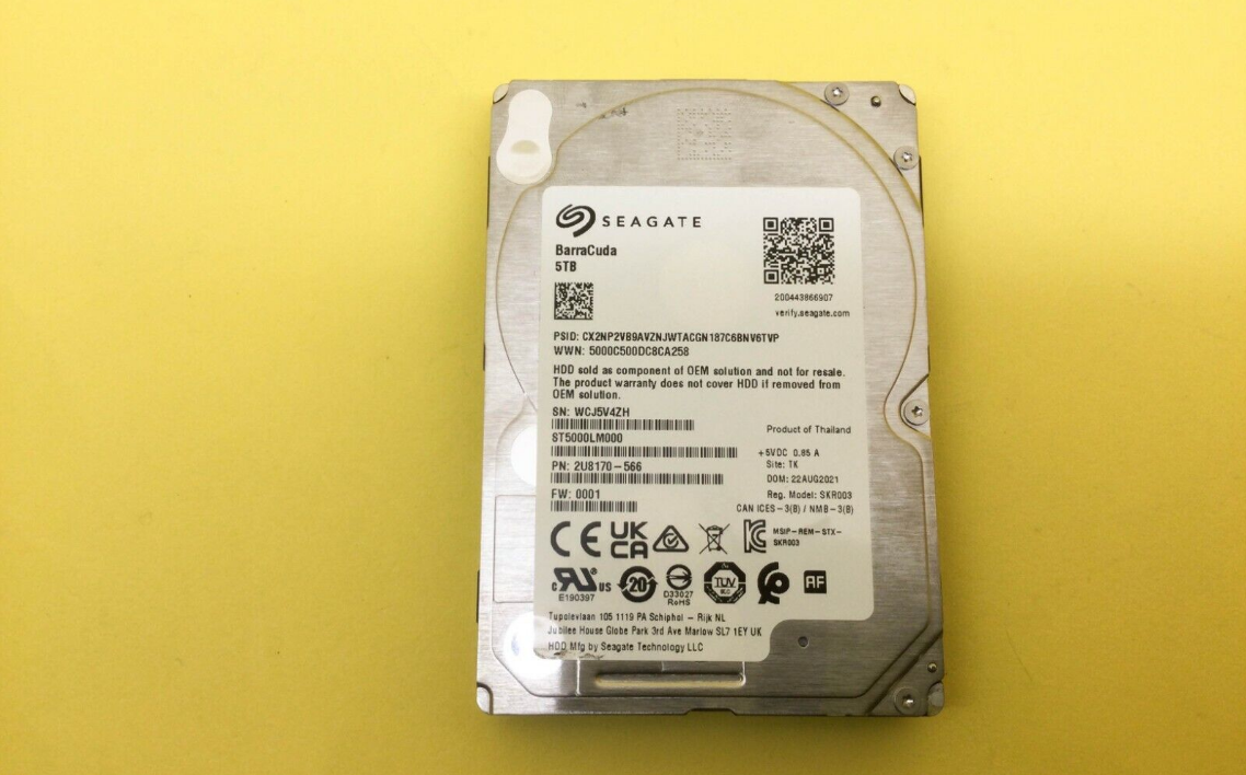
The Seagate BarraCuda Internal Hard Drive ST5000LM000-2U8170 is a high-capacity 5TB storage solution designed for both desktop and laptop computers. With its 5400 RPM speed, it offers a balance of performance and energy efficiency, making it suitable for a variety of applications, including gaming, multimedia storage, and everyday computing tasks. The drive features a SATA interface for easy installation and compatibility with most systems. The Seagate BarraCuda ST5000LM000-2U8170 is priced at approximately $109.99.
This manual describes the functional, mechanical and interface specifications for the following: Seagate BarraCuda model drives:
Standard models | |
ST5000LM000- | ST4000LM024- |
2U8170 | 2U817V |
These drives provide the following key features:
- 128MB buffer.
- 5400-RPM spindle speed.
- 650 Gs non-operating shock and 300 Gs of operating shock.
- Full-track multiple-sector transfer capability without local processor intervention.
- High instantaneous (burst) data-transfer rates (up to 6Gb/s).
- MTC TechnologyTM, proprietary data flow management.
- Native Command Queuing (NCQ) with command ordering.
- Quiet operation with Fluid Dynamic Bearing (FDB) motor.
- SeaToolsTM diagnostic software performs a drive self-test that eliminates unnecessary drive returns.
- Shingled magnetic recording with perpendicular magnetic recording heads/media.
- State-of-the-art cache and on-the-fly error-correction algorithms.
- Support for Read Multiple and Write Multiple commands.
- Support for S.M.A.R.T. drive monitoring and reporting.
- Worldwide Name (WWN) capability uniquely identifies the drive.
About the Serial ATA Interface
The Serial ATA interface provides several advantages over the traditional (parallel) ATA interface. The primary advantages include:
- Easy installation and configuration with true plug-and-play connectivity. It is not necessary to set any jumpers or other configuration options.
- Thinner and more flexible cabling for improved enclosure airflow and ease of installation.
- Scalability to higher performance levels.
In addition, Serial ATA makes the transition from parallel ATA easy by providing legacy software support. Serial ATA was designed to allow users t o install a Serial ATA host adapter and Serial ATA disk drive in the current system and expect all of the existing applications to work as normal.
The Serial ATA interface connects each disk drive in a point-to-point configuration with the Serial ATA host adapter. There is no master/slav e relationship with Serial ATA devices like there is with parallel ATA. If two drives are attached on one Serial ATA host adapter, the host operating system views the two devices as if they were both “masters” on two separate ports. This essentially means both drives behave as if they are Device 0 (master) devices.
NOTE
The host adapter may, optionally, emulate a master/slave environment to host software where tw o devices on separate Serial ATA ports are represented to host software as a Device 0 (master) and Device 1 (slave) accessed at the same set of host bus addresses. A host adapter that emulates a master/slav e environment manages two sets of shadow registers. This is not a typical Serial ATA environment.
The Serial ATA host adapter and drive share the function of emulating parallel ATA device behavior to provide backward compatibility with existing host systems and software. The Command and Control Block registers, PIO and DMA data transfers, resets, and interrupts are all emulated.
The Serial ATA host adapter contains a set of registers that shadow the contents of the traditional device registers, referred to as the Shado w Register Block. All Serial ATA devices behave like Device 0 devices. For additional information about how Serial ATA emulates parallel ATA, refer t o the Serial ATA International Organization: Serial ATA (Revision 2.6). The specification can be downloaded from https://www.serialata.org
Specifications
Unless otherwise noted, all specifications are measured under ambient conditions, at 25°C, and nominal power. For convenience, the phrases th e drive and this drive are used throughout this manual to indicate the following drive models:
The specification summaries listed in the following tables are for quick reference. For details on specification measurement or definition, refer to the appropriate section of this manual.
Specification Summary
Table 1 Drive Specifications Summary
| Drive Specification | ST5000LM000-2U8170 | ST4000LM024-2U817V |
| Formatted capacity 1 | 5000GB | 4000GB |
| Guaranteed sectors | 9,767,541,168 | 7,814,037,168 |
| Heads | 10 | 10 / 8 |
| Disks | 5 | 5 / 4 |
| Bytes per sector | 512 (logical) / 4096 (physical) | |
| Recording density | 2254 Kb/in | |
| Track density | 580 Ktracks/in avg | |
| Areal density | 1307 Gb/in2 avg | |
| Spindle speed | 5400 RPM | |
| Data transfer rate (upto) | 140 MB/s | |
| Interface | SATA 6Gb/s | |
ATA data-transfer modes supported | PIO modes 0–4 Multiword DMA modes0–2 Ultra DMA modes0–6 | |
| Cache buffer | 128 MB | |
| Height | 15.0 +0.5/- 0.25 mm (0.59 +0.002/-0.010 in) | |
| Width | 69.85 +/- 0.25mm (2.750 +/- 0.010 in) | |
| Length | 100.35 +0.20 / -0.25 mm (3.951 +0.008 / -0.010 in) | |
| Weight (max) | 190 g (0.42lb) | |
| Average latency | 5.6 ms | |
| Startup current, Max (+5V) | 1.2A | |
| Voltage tolerance (including noise) | 5V ± 5% | |
| Operating temperature | 0° to 60°C | |
| Non-operating temperature (Ambient) | –40° to 70°C | |
| Temperature gradient (max) | 20°C per hour max (operating) 35°C per hour max (non-operating) | |
| Relative humidity | 5% to 95% (operating) 5% to 95%(non-operating) |
| Relative humidity gradient | 20°C per hour max (operating) 30°C per hour max (non-operating) |
| Wet bulb temperature (max) | 37.7°C max (operating) 40.0°C max (non-operating) |
| Altitude, operating | –304.8 m to 3048 m (–1000 ft to 10,000+ ft) |
Altitude, non-operating (below mean sealevel, max) | –304.8 m to 12,192 m (–1000 ft to 40,000+ ft) |
| Operational Shock | 300 Gs at 2 ms max |
| Non-Operational Shock | 650 Gs at 1 ms max |
| Vibration, operating | 10–500 Hz: 0.7 Grms |
| Vibration, non-operating | 5–500 Hz: 2.2 Grms |
| Nonrecoverable read errors | 1 per 1014 bits read |
Rated workload | Average annualized workload rating: <55 TB/year. The specifications for the product assumes the I/O workload does not exceed the average annualized workload rate limit of 55 TB/year. Workloads exceeding the annualized rate may degrade and impact reliability as experienced by the particular application. The average annualized workload rate limit is in units of TB per calendar year. |
Warranty | To determine the warranty for a specific drive, use a web browser to access the following web page: http://www.seagate.com/support/warranty-and-replacements/. From this page, click on the “Is my Drive under Warranty” link. The following are required to be pro- vided: the drive serial number, model number (or part number) and country of purchase. The system will displaythe warranty information for the drive. |
| Load-unload cycles | 600,000 at 25°C,50% rel. humidity |
| Supports Hotplug operation per the SerialATA Revision 3.2 specification | Yes |
- One GB equals one billion bytes when referring to hard drive capacity. Accessible capacity may vary depending on operating environment and formatting.
NOTE
If the drive is powered-off before issuing flush cache command, in some instances, the end user data in the DRAM cache might not be committed to the disk.
Formatted Capacity
| Model | Formatted Capacity1 | Guaranteed Sectors | Bytes per Sector |
| 5TB models | 5000 GB | 9,767,541,168 |
512 (logical) / 4096(physical) |
| 4TB models | 4000 GB | 7,814,037,168 |
- One GB equals one billion bytes when referring to hard drive capacity. Accessible capacity may vary depending on operating environment and formatting.
LBA mode
When addressing these drives in LBA mode, all blocks (sectors) are consecutively numbered from 0 to n–1, where n is the number of guaranteed sectors as defined above.
Refer to Unpacking, Configuring and Mounting the Drive on page 16 (words 60-61 and 100-103) for additional information about 48-bit addressing support of drives with capacities over 137 GB.
Physical organization
Drive model | Read/write heads | Number of discs |
| 5TB models | 10 | 5 |
| 4TB models | 10 / 8 | 5 / 4 |
Recording and Interface Technology
| Interface | Serial ATA (SATA) |
| Recording method | Perpendicular |
| Recording density | 2254 Kb/in |
| Track density | 580 Ktracks/in avg |
| Areal density | 1307 Gb/in2 avg |
| Spindle speed | 5400 RPM |
| Data transfer rate (up to) | 140 MB/s |
| Interface | SATA 6Gb/s |
Physical Characteristics
All models | Height | 15.0 +0.5/- 0.25 mm (0.59 +0.008/-0.010 in) |
Width | 69.85 +/- 0.25 mm (2.750 +/- 0.010 in) | |
Length | 100.35 +0.20 / -0.25 mm (3.951 +0.008 / -0.010 in) | |
Weight (max) | 190 g (0.42lb) | |
Cache buffer | 128 MB (129,536 KB) |
Seek time
Seek measurements are taken with nominal power at 25°C ambient temperature. All times are measured using drive diagnostics. The specifications in the table below are defined as follows:
- Average seek time is determined by averaging the time to complete 1,000 seeks of random length.
- Average latency is the time required for the drive to rotate 1/2 of a revolution and on average is incurred after a seek completion prior to reading or writing user data.
- Startup time is the time elapsed between the supply voltages reaching operating range and the drive being ready to accept all commands.
- Actual rotational speed can be different a little.
- Performance specification is limited to the room temperature & normal voltage condition.
Table 2: Typical seek times
Typical seek times (ms) | Read/Write |
Average | 14.0/14.0 |
Average latency | 5.6 |
Note
Seek time is defined as the time from the receipt of a read, write or seek comman d until the actuator has repositioned and settled on the desired track with the drive operating at nominal DC input voltages and nominal operating temperature.
Start/stop times
Table 3: Start/stop times
Capacity | 5TB and 4TB models |
Typical seek times (ms) | Typical |
Power-on to ready (sec) | 7.5 |
Standby to ready (sec) | 6.5 |
Power Specifications
The drive receives DC power (+5V) through a native SATA power connector (refer to1).
Power consumption
Power requirements for the drives are listed in the table in Table 4. Typical power measurements are based on an average of drives tested, unde r nominal conditions, at 25°C ambient temperature. These power measurements are done with DIPM enabled.
- Spinup current is measured from the time of power-on to the time that the drive spindle reaches operating speed.
- Read/Write current is measured with the heads on track, based on three 64 sector read or write operations every 100 ms.
- The drive supports two idle modes: Active Idle mode and Low Power Idle mode. Refer to Section 2.8.4 for power-management modes.
Table 4: DC Power Requirements
| Power Dissipation | All models +5V input average (25° C) |
| Spinup (max) | 1.2A |
| Write average | 2.40W |
| Read average | 2.40W |
| Idle, low power mode | 1.45W |
| Standby1 | 0.18W |
| Sleep | 0.18W |
- Standby power is measured at steady state (after 200ms from transition)
Conducted noise
Input noise ripple is measured at the host system power supply across an equivalent 15-ohm resistive load on the +5 volt line.
Using 5-volt power, the drive is expected to operate with a maximum of 100 mV peak-to-peak square-wave injected noise at up to 20 MHz.
Note
Equivalent resistance is calculated by dividing the nominal voltage by the typical RMS read/write current.
Supply Voltage
| Allowable voltage | 5V ± 5% |
| Allowable noise/ripple | 100 mV p-p max, 0-30 MHz |
| Allowable supply rise time | 1-100 ms |
| Allowable supply fall time | <5 s |
Power-management modes
The drive provides programmable power management to provide greater energy efficiency. In most systems, users can control power management through the system setup program. The drive features the following power-management modes:
| Power modes | Heads | Spindle | Electronics |
| Active | Tracking | Rotating | Full Power |
| Idle, Active | Floating | Rotating | Partial Power |
| Idle, Low Power | Parked | Rotating | Partial Power |
| Standby | Parked | Stopped | Low Power |
| Sleep | Parked | Stopped | Low Power |
- Active mode
The drive is in Active mode during the read/write and seek operations. - Idle mode
The electronics remain powered, and the drive accepts all commands and returns to Active mode when disk access is necessary. - Standby mode
The drive enters Standby mode immediately when the host sends a Standby Immediate command. If the host has set the standb y timer, the drive enters Standby mode automatically after the drive has been inactive for a specifiable length of time. The standb y timer delay is established using a Standby or Idle command. In Standby mode, the electronics are in low power mode, the heads are parked and the spindle is at rest. The drive accepts all commands and returns to Active mode when disk access is necessary. - Sleep mode
The drive enters Sleep mode after receiving a Sleep command from the host. In Sleep mode, the electronics are in low power mode, the heads are parked and the spindle is at rest. The drive leaves Sleep mode after it receives a Hard Reset or Soft Reset from the host. After receiving a reset, the drive exits Sleep mode and enters Standby mode.
Environmental Specifications
This section provides the temperature, humidity, shock, and vibration specifications for Seagate BarraCuda drives. Ambient temperature is defined as the temperature of the environment immediately surrounding the drive. Above 1000 feet (305 meters), the maximum temperature is derated linearly by 1°C every 1000 feet.
Table 5: Environmental specifications
Parameters | Operating | Non-Operating |
Ambient temperature | 0° to 60°C (32° to 140°F) | -40° to 70°C (-40°to 158°F) |
Temperature gradient | 20°C per hour (68°Fper hour) max,without condensation | 35°C per hour (95°Fper hour) max,without condensation |
Humidity | 5% to 95%non-condensing (30% perhour) | 5% to 95%non-condensing (30% perhour) |
Wet bulb | 37.7°C (99.8°F) max | 40°C (104°F) max |
Altitude | -304.8m to 3048m (-1000ft to 10,000ft) | -304.8m to 12,192m (-1000ft to 40,000ft) |
Note
The recommended storage period:
- 1 year under controlled conditions of 34°C 90%RH or less
- 90 days in uncontrolled storage conditions
Shock
All shock specifications assume that the drive is mounted securely with the input shock applied at the drive mounting screws. Shock may be applied in the X, Y, or Z axis.
Operating shock
These drives comply with the performance levels specified in this document when subjected to a maximum operating shock of 300 Gs based on half-sine shock pulses of 2 ms. Shocks should not be repeated more than one time per axis. Shocks should not be repeated more than one time per axis. There must be a minimum delay of 3 seconds between pulses.
Non-operating shock
The non-operating shock level that the drive can experience without incurring physical damage or degradation in performance when subsequently put into operation is 650 Gs based on a non-repetitive half-sine shock pulse of 1 ms duration.
Vibration
All vibration specifications assume that the drive is mounted securely with the input vibration applied at the drive mounting screws. Vibration may be applied in the X, Y, or Z axis.
2.9.2.1 Operating vibration
The maximum vibration levels that the drive may experience while meeting the performance standards specified in this document are specified below.
- 10-500 Hz, Sequential 0.7 Grms
Non-operating vibration
The maximum non-operating vibration levels that the drive may experience without incurring physical damage or degradation in performance when subsequently put into operation are specified below.
- 5-500 Hz, Random 2.2 Grms
Acoustics
Drive emission of sound is measured consistent with the ECMA-74 and its referenced standards. Testing is conducted at room temperature (approximately 25°C). Emission levels are reported as the total A-weighted sound power levers for steady state, idle, and active seeks modes of operation.
Table 6: Drive A-weighted Sound Power Levels (SWL, BA)
| Idle1 | Performance Seek |
5-disk models | 2.7 bels (typ) | 2.9 bels (typ) |
4-disk models | 2.6 bels (typ) | 2.7 bels (typ) |
- During periods of drive idle, some offline activity may occur according to the S.M.A.R.T. specification, which may increase acoustic and power to operational levels.
Test for prominent discrete tones (PDTs)
Seagate follows the ECMA-74 standards for measurement and identification of PDTs. An exception to this process is the use of the absolute threshold of hearing. Seagate uses the lower limit for the threshold curve* to discern tone audibility and to compensate for the inaudible components of sound prior to computation of tone ratios according to Annex D of the ECMA-74 standards.
Defined as the median curve given by ISO 389-7 (Tf curve) minus 10dB at all frequencies
Electromagnetic Immunity
When properly installed in a representative host system, the drive operates without errors or degradation in performance when subjected to the radio frequency (RF) environment as defined in Table 7.
Table 7 Radio Frequency Environments
| Test | Description | Performance Criteria | Reference Standard |
| Electrostatic discharge | Contact, HCP, VCP: ± 4 kV; Air: ± 8 kV | B | EN 61000-4-2: 95 |
| Radiated RF immunity | 80 to 1GHz,3 V/m, 80% AM with 1 kHz sine | A | EN 61000-4-3: 96 |
| Electrical fast transient | ± 1 kV on AC mains, ± 0.5 kV on external I/O | B | EN 61000-4-4: 95 |
| Surge immunity | ± 1 kV differential, ± 2 kV common, AC mains | B | EN 61000-4-5: 95 |
| Conducted RF immunity | 150 kHz to 80 MHz, 3 Vrms, 80% AM with1 kHz sine | A | EN 61000-4-6: 97 |
| Power Frequency H-field immunity | 1 A/m, 50Hz/60Hz, 3 axes | A | EN 61000-4-8: 97 |
| Voltage dips, interrupts | 30% Reduction for 25 cycles >95% Reduction for 250 cycles >95%, 0.5 cycles | C C B | EN 61000-4-11: 94 |
Seagate BarraCuda Internal Hard Drive ST5000LM000-2U8170 Reliability
| Nonrecoverable read errors | 1 per 1014 bits read, max |
Load/Unload (U/UL) 25°C, 50% relative humidity |
600,000 software-controlled power on/off cycles 20,000 hard power on/off cycles |
| Rated workload | Average annualized workload rating: <55 TB/year. The specifications for the product assumes the I/O workload does not exceed the average annualized workload rate limit of 55 TB/year. Workloads exceeding the annualized rate may degrade and impact reliability as experienced by the particular application. The average annualized workload rate limit is in units of TB per calendar year. |
| Warranty | To determine the warranty fora specific drive, use a web browser to access thefollowing web page: http://www.seagate.com/support/warranty-and-replacements/. From this page,click on the “Is my Drive under Warranty” link.The following are required to be provided: the driveserial number, modelnumber (or partnumber) and countryof purchase. The system will display the warranty information for the drive. |
Data loss under power interruption with write cache enabled
Drive preserves its data during all operations except in cases where power to the drive is interrupted during write operations. This could result in either an uncorrected data error being reported, or the entire sector/track becoming unreadable. This can be permanently recovered by rewriting to the same location on the drive. Additionally any data present in the DRAM buffer will not be written to the disk media, additionally, the drive will not be able to return the original data. In order to prevent this data loss, the host should issue a standby immediate or flush cache command before a controlled power off operation to the drive.
HDD and SSD Regulatory Compliance and Safety
For the latest regulatory and compliance information see: https://www.seagate.com/support/ scroll to bottom of page and click the Compliance, Safety and Disposal Guide link.
Regulatory models
The following regulatory model number represent all features and configurations within the series: SKR003
Corrosive Environment
Seagate electronic drive components pass accelerated corrosion testing equivalent to 10 years exposure to light industrial environments containing sulfurous gases, chlorine and nitric oxide, classes G and H per ASTM B845. However, this accelerated testing cannot duplicate every potential application environment.
Users should use caution exposing any electronic components to uncontrolled chemical pollutants and corrosive chemicals as electronic drive component reliability can be affected by the installation environment. The silver, copper, nickel and gold films used in Seagate products are especially sensitive to the presence of sulfide, chloride, and nitrate contaminants. Sulfur is found to be the most damaging. In addition, electronic components should never be exposed to condensing water on the surface of the printed circuit board assembly (PCBA) or exposed to an ambient relative humidity greater than 95%. Materials used in cabinet fabrication, such as vulcanized rubber, that can outgas corrosive compounds should be minimized or eliminated. The useful life of any electronic equipment may be extended by replacing materials near circuitry with sulfide-free alternatives.
Unpacking, Configuring and Mounting the Drive
This chapter describes how to unpack, mount, configure and connect a BarraCuda. It also describes how to install the drive in systems.
Handling and Static-Discharge Precautions
After unpacking, and before installation, the drive may be exposed to potential handling and electrostatic discharge (ESD) hazards. Observe the following standard handling and static-discharge precautions.
Caution
- Keep the drive in the electrostatic discharge (ESD) bag until ready for installation to limit the drive’s exposure to ESD.
- Before handling the drive, put on a grounded wrist strap, or ground yourself frequently by touching the metal chassis of a computer that is plugged into a grounded outlet. Wear a grounded wrist strap throughout the entir e installation procedure.
- Handle the drive by its edges or frame only.
- The drive is extremely fragile—handle it with care. Do not press down on the drive top cover.
- Always rest the drive on a padded, antistatic surface until mounting it in the computer.
- Do not touch the connector pins or the printed circuit board.
- Do not remove the factory-installed labels from the drive or cover them with additional labels. Removal voids the warranty. Some factory-installed labels contain information needed to service the drive. Other labels are used to seal out dirt and contamination.
Configuring the Drive
Each drive on the Serial ATA interface connects in a point-to-point configuration with the Serial ATA host adapter. There is no master/slave relationship because each drive is considered a master in a point-to-point relationships. If two drives are attached on one Serial ATA host adapter, the host operating system views the two devices as if they were both “masters” on two separate ports. Both drives behave as if they are Device 0 (master) devices.
Serial ATA Cables and Connectors
The Serial ATA interface cable consists of four conductors in two differential pairs, plus three ground connections. The cable size may be 30 to 2 6 AWG with a maximum length of one meter (39.37 in). Refer to Table 8 for connector pin definitions. Either end of the SATA signal cable can be attached to the drive or host.
For direct backplane connection, the drive connectors are inserted directly into the host receptacle. The drive and the host receptacle incorporate features that enable the direct connection to be hot pluggable and blind mateable. For installations which require cables, users can connect the drive as shown in1.
Figure 1 Attaching SATA Cabling
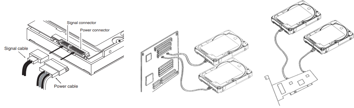
Each cable is keyed to ensure correct orientation. BarraCuda drives support latching SATA connectors.
Drive Mounting
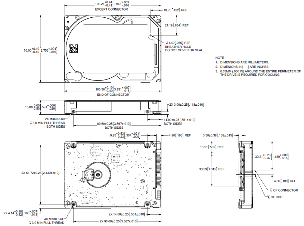
Users can mount the drive in any orientation using four screws in the side-mounting holes or four screws in the bottom-mounting holes. Refer to2 and Figure 2 for drive mounting dimensions. Follow these important mounting precautions when mounting the drive:
- Allow a minimum clearance of 0.030 in (0.76 mm) around the entire perimeter of the drive for cooling.
- Use only M3 x 0.5 mounting screws.
- Do not overtighten the mounting screws. Maximum torque: 4.0 in-lb (0.4519 N-m).
- Four (4) threads (0.080 in, 2.032 mm) minimum screw engagement recommended.
- Avoid excessive drive distortion when mounting. Refer to the following specifications for stiffness/deflection information:
Top cover stiffness/deflection |
|
| Operating: no performance degradation, emitted noise, mechanical damage,or hard errors | 10 mm probe: 2.0kgf (typical) |
| Non-operating: no hard errors | 10 mm probe: maximum 2.0kgf (instantaneous) |
Figure 2 Mounting Dimensions
Description
The Seagate BarraCuda ST5000LM000-2U8170 is engineered to deliver high performance and reliability. With a 5TB capacity, it provides ample storage for large files, including high-definition videos, extensive game libraries, and large datasets. The drive operates at 5400 RPM and features a 128MB buffer, ensuring smooth data transfer and efficient performance. Its compact design makes it suitable for a variety of systems, from home desktops to professional workstations.
Serial ATA (SATA) Interface
These drives use the industry-standard Serial ATA interface that supports FIS data transfers. It supports ATA programmed input/output (PIO) mode s 0–4; multiword DMA modes 0–2, and Ultra DMA modes 0–6. The drive also supports the use of the IORDY signal to provide reliable high-speed data transfers.
For detailed information about the Serial ATA interface, refer to the Serial ATA: High Speed Serialized AT Attachment specification.
Hot-Plug Compatibility
BarraCuda drives incorporate connectors which enable users to hot plug these drives in accordance with the Serial ATA: High Speed Serialized A T Attachment specification revision 2.0. This specification can be downloaded from https://www.serialata.org This device requires a COMRESET from th e host after a hotplug event.
Serial ATA Device Plug Connector Pin Definitions
Table 8 summarizes the signals on the Serial ATA interface and power connectors. Refer to the Table Notes below.
Table 8 Serial ATA Connector Pin Definitions
| Segment | Pin | Function | Definition |
Signal | S1 | Ground | 2nd mate |
| S2 | A+ | Differential signalpair A fromPhy | |
| S3 | A- | ||
| S4 | Ground | 2nd mate | |
| S5 | B- | Differential signalpair B from Phy | |
| S6 | B+ | ||
| S7 | Ground | 2nd mate | |
| Key and spacing separate signal and power segments | |||
Power | P1 | V33 | 3.3V power |
| P2 | V33 | 3.3V power | |
| P3 | V33 | 3.3V power, pre-charge, 2ndmate | |
| P4 | Ground | 1st mate | |
| P5 | Ground | 2nd mate | |
| P6 | Ground | 2nd mate | |
| P7 | V5 | 5V power, pre-charge, 2nd mate | |
| P8 | V5 | 5V power | |
| P9 | V5 | 5V power | |
| P10 | Ground | 2nd mate | |
| P11 | Ground or LED signal | If grounded, drive does not use deferred spin | |
| P12 | Ground | 1st mate | |
| P13 | V12 | 12V power, pre-charge, 2nd mate | |
| P14 | V12 | 12V power | |
| P15 | V12 | 12V power | |
Notes
- All pins are in a single row, with a 1.27 mm (0.050 in) pitch.
- The comments on the mating sequence apply to the case of backplane blindmate connector only. In this case, the mating sequences are:
- the ground pins P4 and P12.
- the pre-charge power pins and the other ground pins.
- the signal pins and the rest of the power pins.
- There are three power pins for each voltage. One pin from each voltage is used for pre-charge when installed in a blind-mate backplane configuration.
- All used voltage pins (Vx) must be terminated.
Supported ATA Commands
Table 9 lists Serial ATA standard commands that the drive supports. For a detailed description of the ATA commands, refer to the Serial AT A International Organization: Serial ATA (Revision 2.6). Refer to https://www.sata-io.org Refer to S.M.A.R.T. commands on page 27 for details and subcommands used in the S.M.A.R.T. implementation.
Table 9 Supported ATA commands
ATA-standard commands names | Command code (in hex) |
| Device Configuration Restore | B1h/C0h |
| Device Configuration Freeze Lock | B1h/C1h |
| Device Configuration Identify | B1h/C2h |
| Device Configuration Set | B1h/C3h |
| Download Microcode | 92h |
| Execute Device Diagnostics | 90h |
| Flush Cache | E7h |
| Flush Cache Extended | EAh |
| Identify Device | ECh |
| Initialize DeviceParameters | 91h |
| Read Buffer | E4h |
| Read DMA | C8h |
| Read DMA Extended | 25h |
| Read DMA without Retries | C9h |
| Read Long with Retries | 22h |
| Read Long without Retries | 23h |
| Read Multiple | C4h |
| Read Multiple Extended | 29h |
| Read Native Max Address | F8h |
| Read Native Max Address Extended | 27h |
| Read Sectors | 20h |
| Read Sectors Extended | 24h |
| Read Sectors without Retries | 21h |
| Read Verify Sectors | 40h |
Read Verify Sectors Extended | 42h | ||
Read Verify Sectors without Retries | 41h | ||
Seek | 70h | ||
Set Features | EFh | ||
Set Max Address | F9h | ||
Note: Individual Set Max commands are identified by the value | Address: | 00H | |
placed in the Set Max Features register as defined to the right. | Password: Lock: | ||
01H 02H | |||
Unlock: | |||
| 03H | ||
Freeze Lock: | |||
| 04H | ||
Set Max Address Ext | 37h | ||
Set Multiple Mode | C6h | ||
S.M.A.R.T. Disable Operations | B0h/D9h | ||
S.M.A.R.T. Enable/Disable Autosave | B0h/D2h | ||
S.M.A.R.T. EnableOperations | B0h/D8h | ||
S.M.A.R.T. Enable/Disable Auto Offline | B0h/DBh | ||
S.M.A.R.T. Enable One Attribute Modification | B0h/E0h | ||
S.M.A.R.T. Execute Offline | B0h/D4h | ||
S.M.A.R.T. Free Fall Protection Host Interface | FEh | ||
S.M.A.R.T. Read Attribute Thresholds | B0h/D1h | ||
S.M.A.R.T. Read Data | B0h/D0h | ||
S.M.A.R.T. Read Log Sector | B0h/D5h | ||
S.M.A.R.T. ReturnStatus | B0h/DAh | ||
S.M.A.R.T. Save Attribute Values | B0h/D3h | ||
S.M.A.R.T. Write Attribute Thresholds | B0h/D7h | ||
S.M.A.R.T. Write Attribute Values | B0h/E1h | ||
S.M.A.R.T. Write Log Sector | B0h/D6h | ||
Trusted Receive | 5Ch | (SED only) | |
Trusted Receive DMA | 5Dh | (SED only) | |
Trusted Send | 5Eh | (SED only) | |
Trusted Send DMA | 5Fh | (SED only) | |
Write Buffer | E8h | ||
Write DMA | CAh | ||
Write DMA Extended | 35h | ||
Write DMA without Retries | CBh | ||
Write Long with Retries | 32h | ||
| Write Long without Retries | 33h |
| Write Multiple | C5h |
| Write Multiple Extended | 39h |
| Write Sectors | 30h, 31h |
| Write Sectors Extended | 34h |
ATA-standard power-management commands | |
| Check Power Mode | E5h |
| Idle | E3h |
| Idle Immediate | E1h |
| Sleep | E6h |
| Standby | E2h |
| Standby Immediate | E0h |
ATA-standard security commands | |
| Security Set Password | F1h |
| Security Unlock | F2h |
| Security Erase Prepare | F3h |
| Security Erase Unit | F4h |
| Security Freeze Lock | F5h |
| Security Disable Password | F6h |
Identify Device command
The Identify Device command (command code ECH) transfers information about the drive to the host following power up. The data is organized as a single 512-byte block of data, whose contents are shown in Table 10. All reserved bits or words should be set to zero. Parameters listed with an “x” are drive-specific or vary with the state of the drive. Refer to Drive Specifications Summary on page 7 for default parameter settings.
The following commands contain drive-specific features that may not be included in the Serial ATA specification.
Table 10 Identify Device command
| Word | Description | Value |
0 | Configuration information:
| 0C5AH |
| 1 | Number of logical cylinders | 16,383 |
| 2 | Specific configuration | C837H |
| 3 | Number of logical heads | 16 |
| 4 | Retired | 0000H |
| 5 | Retired | 0000H |
| 6 | Number of logical sectors per logical track: 63 | 003FH |
| 7–9 | Retired | 0000H |
| 10–19 | Serial number: (20 ASCII characters, 0000H = none) | ASCII |
| 20 | Retired | 0000H |
| 21 | Retired | 8000H |
| 22 | Obsolete | 0004H |
| 23–26 | Firmware revision: (8 ASCII character string, padded withblanks to endof string) | x.xx |
| 27–46 | Drive model number: (40 ASCII characters, padded with blanks to end of string) | ST5000LM000-2U8170 ST4000LM024-2U817V |
| 47 | (Bits 7–0) Maximum sectors per interrupt on Read multiple and Write multiple (16) | 8010H |
| 48 | Trusted Computing Feature set options | 4001H |
| 49 | Standard Standby timer, IORDY supported and may be disabled | 2F00H |
| 50 | Capabilities | 4000H |
| 51 | PIO data-transfer cycletiming mode | 0200H |
| 52 | Retired | 0200H |
| 53 | Words 54–58, 64–70and 88 are valid | 0007H |
| 54 | Number of current logical cylinders | xxxxH |
| 55 | Number of current logical heads | xxxxH |
| 56 | Number of current logical sectors per logical track | xxxxH |
| 57–58 | Current capacity in sectors | xxxxH |
| 59 | Number of sectors transferred during a Read Multiple or Write Multiple command | xxxxH |
| 60–61 | Total number of user-addressable sectors This field contains a value thatis one greaterthan the totalnumber of user-addressable sectors. The maximum value that shall be placed in this field is 0FFFFFFFh. The 0FFFFFFFh valueapplies to allcapacities over 137GB (see Section 2.2, Formatted Capacity for related information). | ST5000LM000-2U8170 = 0FFFFFFFh ST4000LM024-2U817V = 0FFFFFFFh |
| 62 | Retired | 0000H |
| 63 | Multiword DMA activeand modes supported (see note following this table) | xx07H |
| 64 | Advanced PIO modessupported (modes 3 and 4 supported) | 0003H |
| 65 | Minimum multiword DMA transfer cycle time per word (120 ns) | 0078H |
| 66 | Recommended multiword DMA transfer cycle time per word (120 ns) | 0078H |
| 67 | Minimum PIO cycle time without IORDY flow control (240 ns) | 0078H |
| 68 | Minimum PIO cycle time with IORDY flow control (120 ns) | 0078H |
| 69 | Additional Supported bits Bit 4 means Device Encrypts All User Data on the device. Bit 7 means IEEE1667 protocol is supported. | xx1xH or xx9xH |
| 70–74 | ATA-reserved | 0000H |
| 75 | Queue depth | 001FH |
| 76 | Serial ATA capabilities | 0D06H |
| 77 | ATA-reserved | 0000H |
| 78 | Serial ATA features supported | 0048H |
| 79 | Serial ATA features enabled | 0048H |
| 80 | Major version number | 01F0H |
| 81 | Minor version number | 0029H |
| 82 | Command sets supported | 746BH |
| 83 | Command setssupported | 7D69H |
| 84 | Command sets support extension | 61E3H |
| 85 | Command sets enabled | 7469 |
| 86 | Command sets enabled | BC49H |
| 87 | Command sets enableextension | 61E3H |
| 88 | Ultra DMA support and current mode (see note following this table) | xx7FH |
| 89 | Security erase time | xxxxH |
| 90 | Enhanced security erase time | xxxxH |
| 91 | Current APM values | 8080H |
| 92 | Master password revision code | FFFEH |
| 93 | Hardware reset value (see description following this table) | xxxxH |
| 94 | Auto acoustic management setting | xxxxH |
| 95 | Stream Min. Request Size | 0000H |
| 96 | Streaming Transfer Time - DMA | 0000H |
| 97 | Streaming Access Latency - DMA andPIO | 0000H |
| 98-99 | Streaming Performance Granularity | 0000H |
| 100–103 | Total number of user-addressable LBA sectorsavailable (see Section 3.2,Configuring the Drivefor related information) These wordsare required for drives that support the 48-bit addressing feature. Maximum value:0000FFFFFFFFFFFFh. | ST5000LM000-2U8170 = 9,767,541,168 ST4000LM024-2U817V = 3,907,029,168 |
| 104 | Streaming Transfer Time- PIO | 0000H |
| 105 | Reserved | 0000H |
| 106 | Physical sector size/ Logical sectorsize | 6003H |
| 107 | Seagate reserved | 0000H |
| 108-111 | The mandatory valueof the worldwide name (WWN)for the drive.NOTE: This field is validif word 84,bit 8 is set to 1 indicating 64-bit WWN support. | Each drive will have a unique value. |
| 112-118 | ATA-reserved | 0000H |
| 119 | Free Fall Protection support (bit 5) | 1 = FreeFall Protection supported 0 = Free Fall Protection not supported |
| 120 | Free Fall Protection enable/disable (bit 5) | 1 = Free Fall Protection feature is enabled 0 = Free FallProtection feature is disabled |
| 121–127 | ATA-reserved | 0000H |
| 128 | Security status | 0021H |
| 129–159 | Seagate-reserved | xxxxH |
| 160–221 | ATA-reserved | 0000H |
| 222 | Transport major version number | 101FH |
| 223–254 | ATA-reserved | 0000H |
| 255 | Integrity word | xxA5H |
Table 11 Bit Descriptions
| Description (if bit is set to 1) | |
| Bit | Word 63 |
| 0 | Multiword DMAmode 0 is supported. |
| 1 | Multiword DMAmode 1 is supported. |
| 2 | Multiword DMAmode 2 is supported. |
| 8 | Multiword DMA mode 0 is currently active. |
| 9 | Multiword DMA mode 1 is currently active. |
| 10 | Multiword DMAmode 2 is currently active. |
| Bit | Word 88 |
| 0 | Ultra DMA mode 0 is supported. |
| 1 | Ultra DMA mode 1 is supported. |
| 2 | Ultra DMA mode 2 is supported. |
| 3 | Ultra DMA mode 3 is supported. |
| 4 | Ultra DMA mode 4 is supported. |
| 5 | Ultra DMA mode 5 is supported. |
| 6 | Ultra DMA mode 6 is supported. |
| 8 | Ultra DMA mode 0 is currently active. |
| 9 | Ultra DMA mode 1 is currently active. |
| 10 | Ultra DMA mode 2 is currently active. |
| 11 | Ultra DMA mode 3 is currently active. |
| 12 | Ultra DMA mode 4 is currently active. |
| 13 | Ultra DMA mode 5 is currently active. |
| 14 | Ultra DMA mode 6 is currently active. |
| Bit | Word 93 |
| 13 | 1 = 80-conductor cable detected, CBLID above VIH 0 = 40-conductor cable detected, CBLID belowVIL |
Set Features command
| 02H | Enable write cache (default). |
| 03H | Set transfer mode (based on value in Sector Count register). Sector Count register values: 00H Set PIO mode to default (PIOmode 2). 01H Set PIOmode to default and disable IORDY(PIO mode 2). 08H PIO mode 0 09H PIO mode 1 0AHPIO mode 2 0BH PIO mode3 0CHPIO mode 4 (default) 20HMultiword DMA mode 0 21H Multiword DMA mode 1 22H Multiword DMA mode 2 40H Ultra DMA mode 0 41H Ultra DMA mode 1 42H Ultra DMA mode 2 43H Ultra DMA mode 3 44H Ultra DMA mode 4 45H Ultra DMA mode 5 46H Ultra DMA mode6 |
| 55H | Disable read look-ahead (read cache) feature. |
| 82H | Disable write cache |
| AAH | Enable read look-ahead (readcache) feature (default). |
| C1H | Disable the Free Fall Protection feature (41H above enables the FreeFall Protection feature) |
| F1H | Report full capacity available |
NOTE: At power-on, or after a hardware or software reset, the default values of the features are as indicated above
S.M.A.R.T. commands
S.M.A.R.T. provides near-term failure prediction for disk drives. When S.M.A.R.T. is enabled, the drive monitors predetermined drive attributes that are susceptible to degradation over time. If self-monitoring determines that a failure is likely, S.M.A.R.T. makes a status report available to the host. Not all failures are predictable. S.M.A.R.T. predictability is limited to the attributes the drive can monitor. For more information on S.M.A.R.T. commands and implementation, see the Draft ATA-5 Standard.
SeaTools diagnostic software activates a built-in drive self-test (DST S.M.A.R.T. command for D4H) that eliminates unnecessary drive returns. Th e diagnostic software ships with all new drives and is also available at: http://www.seagate.com/support/downloads/seatools/
This drive is shipped with S.M.A.R.T. features disabled. Users must have a recent BIOS or software package that supports S.M.A.R.T. to enable thi s feature. The table below shows the S.M.A.R.T. command codes that the drive uses.
Table 13 S.M.A.R.T. Commands
Code in features register | S.M.A.R.T. command |
D0H | S.M.A.R.T. Read Data |
D2H | S.M.A.R.T. Enable/Disable Attribute Autosave |
D3H | S.M.A.R.T. Save Attribute Values |
D4H | S.M.A.R.T. Execute Off-line Immediate (runs DST) |
D5H | S.M.A.R.T. Read Log Sector |
D6H | S.M.A.R.T. WriteLog Sector |
D8H | S.M.A.R.T. EnableOperations |
D9H | S.M.A.R.T. DisableOperations |
DAH | S.M.A.R.T. ReturnStatus |
NOTE: If an appropriate code is not written to the Features Register, the command is aborted and 0x 04 (abort) is written to the Error register.
Setup Guide
- Power down your computer before installation.
- Locate an available SATA port on your motherboard.
- Connect the SATA cable to both the hard drive and the motherboard.
- Secure the hard drive in a mounting bracket or bay using screws.
- Power on your computer and enter the BIOS settings to detect the new drive.
- Format the drive using your operating system's disk management tool.
Troubleshooting
Drive Not Detected:
Ensure the drive is properly connected to the motherboard and power supply.
Check BIOS settings to see if the drive is recognized.
Try connecting the drive to a different SATA port or using a different SATA cable.
Slow Performance:
Run a disk defragmentation tool if using Windows.
Check for background applications that may be using disk resources.
Ensure that the drive is not nearly full; try to keep at least 10-15% free space.
Unusual Noises:
If you hear clicking or grinding noises, it may indicate a mechanical failure. Backup your data immediately and consider replacing the drive.
File Corruption:
Run a disk check using tools like CHKDSK (Windows) or Disk Utility (Mac) to scan for and repair file system errors.
Seagate BarraCuda Internal Hard Drive ST5000LM000-2U8170 Pros & Cons
Pros
- High storage capacity of 5TB
- Reliable performance with 5400 RPM and 128MB buffer
- Compact design suitable for various systems
- Good value for price
Cons
- Lower rotational speed compared to some other models
- No built-in encryption or advanced security features
- May not be suitable for extreme performance requirements
Customer Reviews
Common complaints include occasional issues with drive recognition and minor noise during operation. Despite these, the overall consensus is that this drive offers excellent value for its price and capacity.
Faqs
What is the storage capacity of the Seagate BarraCuda?
What interface does this hard drive use?
What is the rotational speed of this hard drive?
How much buffer does this hard drive have?
Is this hard drive suitable for gaming systems?
How do I install the Seagate BarraCuda ST5000LM000-2U8170 in my computer?
Why might my computer not recognize the new hard drive?
What should I do if I encounter data loss or corruption on this hard drive?
Is the Seagate BarraCuda ST5000LM000-2U8170 compatible with both Windows and macOS?
Leave a Comment