Speedtechlights K-FORCE Full Light Bar F-TKFTOW55 User Manual
Content
Introduction
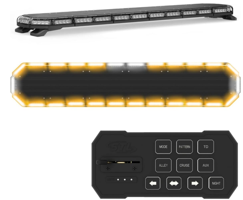
The Speed Tech Lights K-FORCE Full Light Bar F-TKFTOW55 is a high-performance lighting solution designed for emergency vehicles and off-road applications. This durable light bar features multiple flash patterns and powerful LEDs, ensuring maximum visibility in critical situations. Its sleek design and robust construction make it suitable for various environments, providing reliable performance under challenging conditions. The K-FORCE light bar is priced at approximately $499, making it an excellent investment for safety and visibility.
Accessories
Foot Brackets
(Included)
_speed_tech_lights_k-force_full_light_bar_f-tkftow55.png)
- This unit comes included with adjustable Foot Brackets.
- Adjust the Foot Brackets along the length of the aluminum track accordingly to create a flat, even contact with the roof.
Universal Mounting Brackets
(Included)
_speed_tech_lights_k-force_full_light_bar_f-tkftow55.png)
- This unit comes included with Universal Mounting Brackets.
- Adjust the Foot Brackets along the length of the aluminum track accordingly to reach the Universal Bracket and create a flat, even contact with the roof.
- Attach the Universal Bracket to the Light Bar Foot Bracket using the included I-bolt.
- Secure the Universal Bracket to the vehicle via the 2 pre-drilled holes, and user supplied screws at the bottom of the Bracket.
- Tighten the I-bolt equally on both sides to tightly secure everything together.
Vehicle Specific Mounting Brackets
(Sold Separately)
_speed_tech_lights_k-force_full_light_bar_f-tkftow55.png)
- Adjust the Foot Brackets along the length of the aluminum track accordingly to reach the Universal Bracket and create a flat, even contact with the roof.
- Attach the Vehicle Specific Bracket to the Light Bar Foot Bracket using the included I-bolt.
- Secure the Vehicle Specific Bracket to the vehicle via the 2 pre-drilled holes, and user supplied screws at the bottom of the Bracket.
- Tighten the I-bolt equally on both sides to tightly secure everything together.
Stud Mount
(Sold Separately)
_speed_tech_lights_k-force_full_light_bar_f-tkftow55.png)
- Loosen the hardware securing the Foot Bracket to the Light Bar and remove the Foot Bracket from the Light Bar.
- Place the main mounting bolt through the Stud Mount.
- Use the screws that were securing each Magnet Mount to the Light Bar and attach the Stud Mount to the Light Bar.
- Fully tighten the hardware to secure the Stud Mount to the Light Bar.
Headache Rack Mount
(Sold Separately)
_speed_tech_lights_k-force_full_light_bar_f-tkftow55.png)
- Loosen the hardware securing the Foot Brackets to the Light Bar and remove the Foot Brackets from the Light Bar.
- Use the screws that were securing each Foot Brackets to the Light Bar and attach the Headache Rack Bracket to the Light Bar using the two vertical cutaways on the Headache Rack Mount. This secures the Headache Rack Mount to the Light Bar.
- The Headache Rack Mount may then be directly mounted. Or, by using the supplied secondary piece, you may “sandwich” the back rack with 2 user supplied nuts and bolts.
Extension Cable
(Sold Separately)
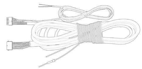
- If you have an extension cable with connectors, connect the corresponding ends to one another. Use the connector at the end of the cable to plug into the control box.
- If you have an extension cable with one connector, you will need to cut the connector off of the main cable harness coming out of the Light Bar. Save it as a spare part. You will solder and heat shrink each wire within the cable harness to each wire in the extension cable harness. DO NOT cross connect wires. Use the connector at the end of the extension cable to plug into the control box.
- If you have an extension cable with no connectors, you will need to cut in the middle of the main cable harness coming out of the Light Bar. You will solder and heat shrink each wire within the cable harness to each wire in the extension cable harness. DO NOT cross connect wires. Use the reattached connector from the end of the main cable harness to plug into the control box.
NOTE: DO NOT leave connectors, cables, solder points exposed to heat, moisture, or debris.
Flash Pattern List
- Steady Burn
- Triple Flash Left/Right Alternating
- Double Flash Left/Right Alternating
- Triple Flash Alternating
- Double Flash Alternating
- Triple Flash Left/Right
- Double Flash Left/Right
- Single Flash Left/Right
- Single Flash Left/Right and Full Combo
- Center Out
- Single Flash
- Single and Quad Flash Full Combo
- Single and Triple Flash Full Combo
- Steady Burn Right Half
- Steady Burn Left Half
- Rapid Pulse Right Half
- Rapid Pulse Left Half
- Steady Burn Right Half. Quad Flash Left Half
- Steady Burn Left Half. Quad Flash Right Half
- Steady Burn Right Half. Single Flash Left Half
- Steady Burn Left Half. Single Flash Right Half
- Quad Flash Left/Right Alternating
- Stacking Right to Left
- Stacking Left to Right
- Stacking and Collapsing Left Right Left
- Single Flash Clockwise Rotation Single LED Chase
- Single Flash Counter Clockwise Rotation Single LED Chase
- Single Flash Clockwise Rotation Double LED Chase
- Single Flash Counter Clockwise Rotation Double LED Chase
- Single Flash Left/Right 120 FPM
- Single Flash 75 FPM
- Accelerating Flash Alternating
Flash Pattern Shortcuts
- Hold for 2 seconds to toggle Steady Burn mode.
- Hold for 3 seconds to toggle Random pattern mode.
About Flash Patterns
- All STL LED products are equipped with a non-volatile memory which will recall the last flash pattern when the Light Bar is turned on.
- Set the flash pattern by pushing the Flash Pattern button on the Supreme Control Box to cycle through the various patterns.
- If you are not using the Supreme Control Box, follow the wiring diagram to identify the Flash Pattern wire to manually cycle through patterns.
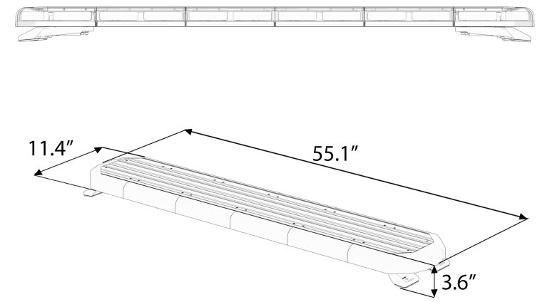
Specifications of Speedtechlights K-FORCE Full Light Bar F-TKFTOW55
Voltage | 12VDC |
Amps | < 18.2 |
Optic | TIR/ Linear |
LED Count | TIR: 104 / Linear: 156 |
Cable Length | 12’ Light Bar Cable, 12.5’ Cig Plug Cable, 12.5’ AUX Cable |
Tow CableLength | 8’ Tow Cable |
Flash Patterns | 33 |
Description
The speedtechlights K-FORCE Full Light Bar F-TKFTOW55 is crafted with precision and durability in mind. Its aluminum housing provides excellent heat dissipation, ensuring the LEDs maintain their performance over time. The polycarbonate lens is impact-resistant, protecting the LEDs from environmental hazards. The adjustable mounting brackets allow for versatile installation options on various vehicle types.
The light bar features a spot/flood beam pattern, providing both long-distance illumination and wide-angle coverage. This makes it perfect for tasks such as off-roading, construction work, or simply enhancing nighttime driving visibility.
Warnings and Notices for Users and Installers
This document must be delivered to and read by the end user and installer as it serves to provide you with the required information for proper and safe use of your STL product. Before operating this or any STL products the user and installer must read this manual all the way through. You will find important information in this manual that could prevent property damage and/or serious injury to the user and installer.
STL products are intended to alert pedestrians and other operators of the presence of personnel, the operation of emergency vehicles, an emergency site, and any warning needs. This does not ensure that pedestrians or drivers will react, heed, or observe emergency warning signals. Nor does the use of emergency signals grant or ensure you the right of way. It is your responsibility to make sure you can proceed safely before driving against traffic, entering an intersection, responding at a high rate of speed, or walking on or around traffic lanes.
Your STL emergency vehicle devices should be tested daily to ensure the device and all its functions are operating correctly. If you experience a malfunction contact STL’s Customer Service immediately for troubleshooting options, or a warranty or service claim. You must ensure that the projection of the visual and audible signal is not blocked by vehicle components (i.e.: open trunks, visors, compartment doors), vehicles, other obstructions, or people.
This is professional grade equipment and is intended for strict use by authorized personnel only. It is the user’s responsibility to understand and obey all laws regarding emergency warning devices. You must know and be familiar with all applicable city, state, and federal laws and regulations prior to the use of emergency vehicle warning devices. SpeedTech Lights, Inc assumes no liability for any loss resulting from the use of this warning device. Proper installation is vital to the performance of the warning devices and safe operation of the emergency vehicle. Since the operator is under stressful environments the equipment must be properly wired and mounted to ensure effectiveness and safety. Therefore controllers must be properly installed and placed within convenient reach of the operator so eye contact with the roadway is never lost.
The effectiveness of your STL equipment is highly dependent upon correct mounting and wiring. Improper wiring and mounting of the warning device will reduce the output and performance of the equipment. Emergency warning devices frequently require high electrical voltages and/or currents. Properly protect and use caution around live electrical connections. Grounding or shorting of electrical connections can cause high current arcing, which can cause severe personal injury and/or serious vehicle damage, including fire.
Electromagnetic interference can be caused by many electronic devices used in emergency vehicles. To ensure that this doesn’t happen to you, Light Bars should be mounted a minimum of 12” - 34” from the radio antenna and do not power your equipment from the same circuit or share the same grounding circuit with radio communication equipment. After installation, test all the vehicle’s equipment together to ensure everything operates free of interference.
Driver and/or passenger airbags (SRS) will impact the way you mount your equipment. Any equipment installed in the deployment area of the airbags will damage or dislodge the airbags and sensors. This will also reduce the effectiveness of the airbags to protect the passengers and therefore these areas must be avoided. Installers must make sure that this equipment along with any parts, hardware, wiring, power supplies, and switch boxes do not interfere with the airbags, SRS wiring, or sensors.
All STL equipment needs to be mounted and installed according to the vehicle manufacturer’s instructions and securely attached to a part of the vehicle of sufficient strength to withstand the forces applied by the equipment. This device should be permanently mounted within the zones specified by the vehicle manufacturer. This especially applies to equipment mounted on the exterior of the vehicle to avoid dislodging. Mounting units on the interior of the vehicle by a method other than permanent mount is discouraged as it may become detached under aggressive driving conditions such as sudden braking, collision, or swerving.
PROPER INSTALLATION COMBINED WITH OPERATOR TRAINING IN THE PROPER USE OF EMERGENCY WARNING DEVICES IS ESSENTIAL TO ENSURE THE SAFETY OF EMERGENCY PERSONNEL AND THE PUBLIC.
Unpacking Your STL Product
- Unpack your unit to identify all parts including but not limited to: Light Bar, switch box, brackets, screws, bolts, wiring harness, fuses, etc.
- Some parts may be in small bags.
- Some products may be packaged inside boxes of other products.
- Some parts such as Gutter Brackets, may be in the foam protection. Double check that no parts are left within the foam protection or left in the box.
Important Points for Your Safety and Longevity of Your Light Bar
- Installers are required to have a good understanding of automotive electronic systems and procedures for proper installation.
- Never stare directly into the LEDs as momentary blindness and/or eye damage may occur.
- Never take any lights through a car wash. Use only water to clean the outer body/lens of your equipment.
- Never use a pressure washer to clean any STL products. Inspect and test your product daily to ensure it operates properly and is mounted correctly.
- Never cut wires or work on a unit while the unit is still connected to a power source.
- Never install this product or route any wires through or in the deployment area of the airbag. Doing so may cause serious personal injury as it will damage or reduce the effectiveness of the airbag by causing the unit to become a projectile. Reference the owner’s manual for your vehicle to find the airbag deployment area. The User/Installer assumes all responsibility to determine proper mounting location, based on providing ultimate safety to all passengers in the vehicle.
- If the product requires you to drill holes, the installer must ensure that the drilling process does not damage any vehicle components or other vital parts. Check all sides of the mounting surface before beginning to drill. Make sure to deburr all drilled holes and remove any metal remnants or shards to avoid injury and wires from becoming spliced. Grommets are to be installed in all wire passage holes.
- Grommets, cable ties, looms, and other installation hardware should be used to anchor and protect all wiring. Fuses should be properly sized and located as close to the power take off points as possible to protect the wiring and device. To protect against short circuits, a fuse is included by STL for all products. DO NOT use a fuse with a higher amp rating than the initial fuse included by STL for all products.
- Insulation displacement connectors are not to be used.
- In order for STL products to operate at optimum efficiency, a secure and good electrical connection to the battery’s Ground Post must be made. The recommended procedure requires the unit’s ground wire be connected directly to the NEGATIVE (-) battery post. DO NOT use Circuit Breaks.
- Instruction manuals should be stored in a safe place for reference if you need to reinstall the unit or perform maintenance. They can also be found at the main site under the product listing at www.SpeedTechLights.com. If your product is no longer available on the website contact STL’s Customer Service at 800-757-2581 for assistance.
- If your product requires the use of a control box or remote device to turn on and control your equipment, make sure it is installed in a location that allows both the user and the vehicle to operate safely in any driving condition.
- Never activate or control your equipment in hazardous driving conditions.
- Use SXL type wire in the engine compartment where higher heat resistance is required according to SAE J-1128. All wires should be in accordance with the minimum wire size and other recommendations made by the manufacturer and be protected from hot surfaces and moving parts.
- FAILURE TO FOLLOW THESE SAFETY PRECAUTIONS, WARNINGS, NOTICES, AND INSTRUCTIONS COULD RESULT IN DAMAGE TO THE PRODUCT OR VEHICLE THAT WILL VOID YOUR WARRANTY AND/OR CAUSE SERIOUS INJURY TO YOU AND YOUR PASSENGER.
Setup Guide
- To set up your speedtechlights K-FORCE Full Light Bar F-TKFTOW55, follow these steps:
- Mount the light bar using the provided adjustable brackets. Ensure they are securely fastened to your vehicle's roof or bumper.
- Connect the wiring harness to your vehicle's electrical system. Make sure all connections are secure and insulated.
- Test the light bar to ensure it is functioning correctly. Adjust the beam pattern as needed for optimal performance.
Pre-Installation and Testing
BENCH TEST all units prior to installation by connecting the Positive Cable (Red) and Negative Cable (Black) to a power source to ensure all the features and parts of the Light Bar are functional.
Test Check List:
- LED diode and LED Module functionality
- Flash patterns
- Non-volatile memory
- Physical damage
Maintenance
While STL’s Light Bars are very durable, there are some things you need to keep in mind and practice to preserve the longevity and function of your Bar.
- Never take any STL Light Bars through a car wash, such as a pressure washer, automatic car wash, brushes that will scratch your equipment or similar car washes or equipment where chemicals, high pressure water, and materials may scratch or damage your equipment.
- Use Water (H2O) with a soft cloth to clean your Light Bar and lenses.
- Yellowing of clear lenses may occur overtime. Lenses can be purchased by calling STL.
Wiring Diagram
* Indicates a main power cable.
Wire Color | Function |
Red (Thick)* | Positive |
Black (Thick)* | Negative |
Brown | Forward Facing Lights |
Light Blue | Rear Facing Lights |
Purple | Full 360° Warning Lights |
Yellow | Flash Pattern |
Light Green | Take Down |
Green | Alley |
NOTE: All cables except Negative contact +12 VDC.
Wire Color | Function |
Blue | Left Arrow |
White | Center Out Arrow |
Orange | Right Arrow |
Grey | Cruise Lights (4 Corners) |
Red (Thin)* | Control Box In Positive |
Black (Thin)* | Control Box In Negative |
Pink (Thin)* | Control Box OutPositive |
Yellow/Green (Thin)* | Control Box OutNegative |
Stop / Tail / Turn Wiring Diagram
Wire Color | Function |
Red | Stop / Turn Driver Side |
Black | Stop / Turn PassengerSide |
Yellow | Tail |
AUX Wiring Diagram
Wire Color | Function |
Red | AUX Positive |
Blue | AUX Negative |
Supreme Control Switch Box Operation
(Sold Separately)
_speed_tech_lights_k-force_full_light_bar_f-tkftow55.png)
-speed_tech_lights_k-force_full_light_bar_f-tkftow55.png)
Slide Switch:
- Off position: Turns off warning functions of the Light Bar.
- 1st position: Powers only the back of the Bar and rear facing 45° warning modules.
- 2nd position: Powers only the front of the Bar and forward facing 45° warning modules.
- 3rd position: Powers all warning functions of the Light Bar.
Take Down Button
- 1st press: TD Steady Burn On.
- 2nd press: TD Off.
Alley Button
- 1st press: Alley Steady Burn On.
- 2nd press: Alley Off.
Traffic Advisor Buttons
- Traffic Advisor LEDs will flash in sequence with warning mode when not activated.
- Left Arrow: Right to Left Traffic Sweep.
- Center Out Arrow: Center Out Traffic Sweep.
- Right Arrow: Left to Right Traffic Sweep.
Flash Pattern Button
- Cycles to the next flash pattern with each press.
- Non-Volatile memory recalls the last flash pattern selected.
- Hold for 2 seconds to toggle Steady Burn mode.
- Hold for 3 seconds to toggle Random pattern mode.
Cruise Button (45° (Four Corner) Modules)
- 1st press: Cruise Steady Burn On.
- 2nd press: Cruise Off.
AUX Button
- Toggle power to AUX cables On and Off.
Back Plate Mount
- Included with Supreme Control Switch Box purchase.
Warning lights do not need to be activated for these Buttons to function.
Troubleshooting
If you encounter any issues with your speedtechlights K-FORCE Full Light Bar F-TKFTOW55, here are some common problems and solutions:
- No Light Output: Check all electrical connections for any signs of damage or wear. Ensure the wiring harness is properly connected to your vehicle's battery and ignition system.
- Dim Light Output: Inspect the LEDs for any signs of damage or debris accumulation. Clean the lens if necessary and ensure proper heat dissipation.
Instructions & Warnings: Always follow safety guidelines when handling electrical components. Avoid exposing the light bar to direct water spray or immersion.
Speedtechlights K-FORCE Full Light Bar F-TKFTOW55 Pros & Cons
Pros:
- High Lumen Output: Provides exceptional brightness for clear visibility in dark conditions.
- Durable Construction: Robust aluminum housing with impact-resistant polycarbonate lens.
- Adjustable Mounting: Versatile installation options with adjustable brackets.
Cons:
- Higher Cost: Priced around $500, which may be out of budget for some users.
- Complex Installation: Requires some technical knowledge for proper wiring and mounting.
Customer Reviews
Customers have praised the Speedtechlights K-FORCE Full Light Bar F-TKFTOW55 for its outstanding performance and durability:
- "The K-FORCE light bar has transformed my nighttime driving experience with its incredible brightness and coverage." - John D.
- "The adjustable mounting brackets made installation a breeze. Highly recommend this product!" - Sarah K.
However, some users have noted that the higher price point and complex installation process are drawbacks:
- "While it's an excellent product, the cost is steep for my budget." - Michael T.
- "Installation required more effort than expected, but it was worth it in the end." - Emily W.
Faqs
What type of LEDs are used in the K-FORCE Full Light Bar?
What is the beam pattern of the K-FORCE Full Light Bar?
Is the K-FORCE Full Light Bar water-resistant?
How do I assemble and configure the K-FORCE Full Light Bar?
What should I do if the light bar does not turn on?
Can I adjust the mounting of the K-FORCE Full Light Bar?
How long does the K-FORCE Full Light Bar last?
Is the K-FORCE Full Light Bar suitable for all vehicle types?
What safety precautions should I take when installing the K-FORCE Full Light Bar?
Leave a Comment