Topens Sliding Gate Opener CK1200 User Manual | Specs
Content
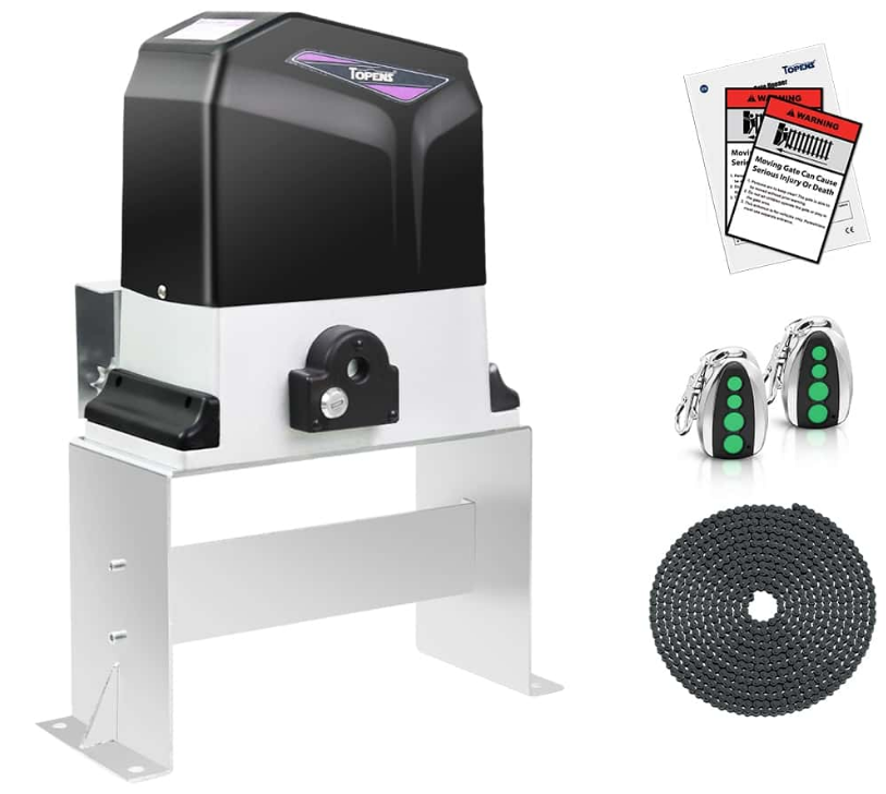
Introducing the Topens Sliding Gate Opener CK1200
TOPENS is a powerful and reliable solution for securing your driveway. Equipped with a strong 3/4 HP 550W AC motor, it effortlessly operates gates weighing up to 3400 lbs and measuring 40 ft in length. The CK1200 features cutting-edge TOPENS code technology for enhanced security, a midway mode for partial gate opening, and a safety stop-and-reverse module to prevent accidents. This easy-to-install gate opener comes with a 20ft roller chain and remote control, making it an ideal choice for residential, commercial, and agricultural applications. The TOPENS CK1200 is priced at approximately $499.99.
Detailed Specifications
The Topens Sliding Gate Opener CK1200 boasts several key features that make it stand out in the market. Here are some of the detailed specifications:
- Gate Capacity: Supports gates up to 1200 pounds and 40 feet in length.
- Motor Power: 1200 watts of powerful and efficient motor.
- Speed: Opens gates at a speed of approximately 12 inches per second.
- Control Options: Compatible with remote controls, wall switches, and smart home systems.
- Safety Features: Includes automatic reversal upon encountering obstacles and a manual release mechanism
Preparation for Installation
Before proceeding to your opener installation, check if your gate structure is in accordance with the current standards, especially as follows:
The gate sliding track is linear and horizontal, and the wheels are suitable, the gate should be mounted and moving freely. Check that the structure is sufficiently strong and rigid, Make sure that the gate is plumb and level. The fence posts must be mounted in concrete. The gate does not bind or drag on the ground. The opening and closing gate stops are positioned.
WARNING: Remember that control devices are intended to facilitate gate operation, but can not solve problems due to any defects or deficiency resulting from failure to carry out correct installation or maintenance. Take the product out of its packing and inspect it for damage. Should it be damaged, contact your dealer. Remember to dispose of its components (cardboard, polystyrene, nylon, etc.) according to the current prescriptions.
Refer to the following Figures for gate installation

In sake of safety, a positive stop must be mounted on the two end of ground track.


Parts List

Accessories Parts
(Included in some models, refers to the actual package)

Optional Accessories Parts List (Available at TOPENS Store)

Replacement Parts

WARNING: Changes or modifications not expressly specified by this user manual, TOPENS could void the warranty of this equipment.
Technical Specifications
| Specifications | CK1200 |
Power input: | 110V~120V/60Hzor 220~240V/50Hz |
Motor voltage: | 120VAC or 230VAC |
Rated power: | 550W |
Gate movingspeed: | 20 cm/s (8 in/s) |
Max gate weight: | 1500kg (3400lbs) |
Max torque: | 35Nm |
Environmental conditions: | -20℃~ +50℃ (0°F to 120°F) |
Protection class: | IP44 |
Features
- Easy to install, and minimum maintenance requirement
- Midway mode, Quick selection for gate open/close direction
- Get the desired chain tension by adjusting the chain bolts.
- Reliable rolling code technology for remote control
- Emergency release key in case of power failure
- Stop in case of obstruction during gate opening.
- Reverse in case of obstruction during gate closing
- Built in adjustable auto-close (0, 30, 60, 90 seconds)
- Built in max. Motor Running Time (MRT) for multiple safety protection (90 seconds)
- Reliable electromagnetism limit for easy adjustment
- Can be equipped with wide range accessories
Description
The Topens CK1200 Sliding Gate Opener is designed with durability and performance in mind. The device is built with high-quality materials that withstand various environmental conditions. It features a sleek and compact design that fits neatly into most gate setups. The opener includes a sturdy gearbox and a high-torque motor, ensuring consistent and reliable operation. Additionally, it comes with a comprehensive set of accessories, including a remote control, wall switch, and mounting hardware, making installation straightforward.
Installation Overview

Installation of the Opener
Caution
- Be sure that the opener is installed in a level and paralleled position. Improper installation could result in property damage, severe injury, and/or death.
- Before starting installation, ensure that there is no point of friction during the entire movement of the gate and there is no danger of derailment.
- Ensure that the safety side rollers are present.
Necessary Tools: The following tools may be necessary to install the Gate opener. You will need screwdrivers, an electric drill, wire cutters and a wire stripper, a socket set, and possibly access to a welder.

When install the opener, you should build a concrete pad to support the base plate of opener in order to maintain proper stability.
The installation proceeds are as follows:
- Assemble the Base Plate and fix the Opener to the Base Plate.
- Dig a hole for a concrete pad which should be approximately 60 x 32 x 35cm (24〞x 13〞x 14〞).
It may protrude 10 cm (4”) above ground and 25 cm (10”) in depth underground. Increase the pad height if necessary to protect the system from flooding, heavy snow etc. - Prepare one or more conduits for the electrical cables before pour concrete. Remember that cable conduits have to pass through the hole on the base.
- Pour concrete and before it starts to harden, check that it is parallel to the gate leaf and perfectly level.
- Mark the position of four expansion anchors according to the position of mounting hole on the base plate. Double check your marking, move the base plate and drill the 4 holes using a 14mm (9/16”) masonry bit. Put the 4 expansion anchors (provided) into the holes and firmly tighten.
- Mount the base plate to the concrete Pad and firmly tighten, enabling the opener is firmly secured on the concrete pad during the whole gate travel.
Manual Operation
The opener should be put in the manual (emergency release) position before fitting the chain, installing the opener and limit switch. The process is as follows:
Insert and turn the key clockwise 45° to slide the lock cover. Now the key slot appears.

Insert the T-handle Key (provided) to the key slot and turn it in counter-clockwise 135° to disengage the clutch between the gear shaft and power output. Now the opener is in the manual operation.
Installation of chain and chain brackets
- Chain Brackets
- Please refer to below chain brackets figure, which shows “U” bolt, “L” bracket and chain bolt. Use the “U” bolts (square or round) to attach the chain brackets to gate frame.
If Both the square bolts and round bolts are not fit for the gate frame, use the appropriate bolts to attach the chain brackets to gate frame.

- How to install the chain
- Place the chain around the top of the idler wheels and under the drive sprocket in chain box.
- Connect a chain bolt to one end of chain from chain box by using master link. Then insert the chain bolt to the L bracket and fix them each other by washers and nuts temporarily. (Nuts will be further adjusted for a proper chain tension later)
- Connect second chain bolt with another end of chain from chain box, then attach bolt to the L bracket on opposite end of gate using the washers and nuts.
- Make sure that the chain is line up exactly with the position where the chain on the chain idler wheel.
Remove the unwanted length of chain. Set appropriated chain tension by adjusting two chain bolts of the both end.


The chain brackets must be mounted to the same height as the chain on the idler wheels.

Make sure there is 1” distance at least between the wheel cover and the gate after you position the base plate.

Installation of the Magnets

- Before install limit switch, make sure the gate opener is put in manual operation. (the clutch connected with gear shaft is disengaged) and the mains power supply is disconnected.
- Position the two Magnet Components approximately on the gate and move the gate by hand to fix them in place.
Fit magnets bracket
- Push the gate fully closed by hand. Locate and install the magnet bracket so that the opener will stop at the desired close position when the close limit switch approaches it.
- Push the gate fully open by hand. Locate and install the magnet bracket so that the opener will stop at the desired open position when the open limit switch approaches it.
- The lower magnet bracket must be installed at left side and higher magnet bracket must be installed at right side from the view inside of property. Finally adjust the magnet to the proper position by moving the gate with the motor. The magnet should be 20-30mm (0.8-1.2”) away from the magnetic limit switch. If it is too far away, the switch will fail to work.
- The distance between the magnet and the opener should be 10-15mm with the opener cover on. Adjust the position of the magnet until the positions of the opening and closing meet the requirement.
Warning: Improper magnets installation may cause the gate crash into end barrier, which is very dangerous !
Connecting of Power Supply
WARNING: NEVER connect the gate opener to the power outlet before all the installations have been done.
The power supply cord should be at least 3×0.75mm2 (3C×18AWG). Connect the live wire and neutral wire to the “L” (1#) and “N” (3#) terminal of the control board respectively; and connect the earth wire to “ ” (2#) terminal of the control board.

NOTE: The power supply cord is not included in the package.
Connecting of the Control Board
WARNING: Before making any electrical wire connection or/and setting the control board, make sure that the power switch is OFF.
- Motor
The BLACK wire of the motor should be connected into the “6” terminal.
The RED wire of the motor should be connected into the “7” terminal.
The YELLOW wire of the motor should be connected into the “8” terminal. - Start Capacitor
One pin of the start capacitor should be wired to the “7” terminal, another to “8” terminal. - Limit Switches
The RED wire of the limit switches should be connected into the “9” terminal.
The BLACK wire of the limit switches should be connected into the “10” terminal.
The YELLOW wire of the limit switches should be connected into the “11” terminal. - Warning Light (Included in some models, refers to the actual package)
One wire of the warning light should be connected into the “4” terminal, another should be connected into the “5” terminal. Photocell Beam System (PBS) (NO) (Included in some models, refers to the actual package)
Use a 2-core cable to connect the “+ ~” terminal of the photocell’s emitter to the “12” terminal, the “- ~” terminal to the “13” terminal. Also the “+ ~” and “- ~” terminals of the photocell’s receiver should be connected to the “12” and “13” terminals in parallel.
Use another 2-core cable to connect the “NO” terminal of the receiver to the “14” terminal, the “COM” terminal to the “15” terminal.
- Reflection Photocell Sensor (optional)
The “AC10-25V/DC12-30V” terminals of the reflection photocell sensor should be connected to the “12” and “13” terminals, no matter the polarity.
The “NO” terminal should be connected to the “14” terminal.
The “COM” terminal should be connected to the “15” terminal. - Push Button (Optional)
The push button should be wired to the “15” and “16” terminals. The gate opener works alternately by pushing the button (open-stop-close-stop-open). - Exit Wand (Optional)
First insert the Adapter BOARD into the CONTROL BOARD, and then connect the wand to the control board refers to following instruction.
The BLACK wire of the exit wand should be connected into the “#18” terminal.
The BLUE wire of the exit wand should be connected into the “#17” terminal.
The RED wire of the exit wand should be connected into the “#12” terminal.
The GREEN wire of the exit wand should be connected into the “#13” terminal.
The sensitivity adjustment board should be wired to the GREEN wire and the YELLOW wire of the wand. No matter the polarity. - External Receiver (Optional)
The BROWN wire of the external receiver should be connected into the “16” terminal.
The BLACK wire of the external receiver should be connected into the “13” terminal.
The RED wire of the external receiver should be connected into the “12” terminal. - Wired Keypad (12VDC) (Optional)
The RED wire of the wired keypad should be connected into the “12” terminal.
The BLACK wire of the wired keypad should be connected into the “13” terminal.
The PURPLE wire of the wired keypad should be connected into the “16” terminal.
The BLUE wire of the wired keypad should be connected into the “15” terminal. - HomeLink Remote Control Kit (optional)
The “1” terminal should be connected to the “15” terminal.
The “2” terminal should be connected to the “16” terminal.
The “DC+” terminal should be connected to the “12” terminal.
The “DC-” terminal should be connected to the “13” terminal.
Setup Guide
Setting up the Topens Sliding Gate Opener CK1200 is relatively straightforward. Here’s a brief guide to get you started:
- Assemble the Gate Opener: Attach the motor unit to the gate and secure it firmly using the provided mounting hardware.
- Connect Power and Control Devices: Connect the power supply and attach the remote control receiver to the motor unit.
- Configure Settings: Adjust the limit switches to define the open and close positions of your gate.
- Pair Remote Controls: Pair the remote controls with the receiver following the instructions provided in the user manual.
Maintenance
Every six months check the following items for proper operation of the unit.
- Lubricate shafts and sprockets.
- Keep opener clean at all times.
- Check and tighten anchors bolts.
- Check for loose or corroded wire
- Ensure the opener is well earthed, and correctly terminated.
- Always check the Stop/Reverse in case of obstruction function when performing any maintenance. If this function can’t be made operable, remove this opener from service until the cause of the malfunction is identified and corrected.
Setting of the Control Board
WARNING: Ensure the gate opener is Power Off when you make any adjustment of the gate opener. Keep away from the gate during you set the gate opener system in case of the unexpected gate moving. Carefully adjust the DIP switches to avoid the risk of machine damage and injury or death. Always ask the help of professional technician /electrician if you have any question.
DIP Switches
The DIP switches are used to set the running time of the motor in midway mode, auto close time of the gate opener and fast change the open/close direction which is determined by the position of the gate opener installed.
DIP Switch #1–#2: Running time of the motor in Midway Mode
This mode enables user to drive the vehicle through the gate quickly when the gate opens to certain width.- DIP Switch #1: ON – 4 Seconds OFF – 0
- DIP Switch #2: ON – 2 Seconds OFF – 0
NOTE: The midway mode function would be disabled if both DIP switches are turned off. Factory default setting is disabled. The midway mode could be activated by pressing button B of the remote control when the gate is in the full closed position.
E.g. →Running time of the operator in midway mode is 4+2=6 seconds.
DIP Switch #3–#4: Auto close time of the gate opener
- DIP Switch #3: ON – 30 Seconds OFF – 0
- DIP Switch #4: ON – 60 Seconds OFF – 0
NOTE: The auto close function would be disabled if both dip switches are turned to off (factory default setting).
E.g. →Auto close time of the gate operator is 30+60=90 seconds.
Important Note: When the auto close function is enabled, the photocell sensor is highly recommended to be installed with the gate opener for safety.
DIP Switch #5: Left/Right open- ON – Right open (factory default setting).
OFF – Left open. Turn switch OFF to change the opening direction easy if necessary.

Potentiometers
The potentiometer A is to adjust the OPEN stall force of the gate opener. The Potentiometer B is used to adjust the CLOSE stall force of the gate opener.
Turn the potentiometer clockwise to increase the stall force.
Turn the potentiometer counter-clockwise to decrease the stall force.
WARNING: Photocell is highly recommended to be installed with the gate opener as entrapment protection for safety when you set stall force to maximum.
How to Program or Erase the Remote
- The remote MUST be programed to the opener BEFORE OPERATING. Please follow the steps to program the remote.
- Activate the opener only when gate is in full view, free of obstruction and properly adjusted. No one should enter or leave gate area while gate is in motion. DO NOT ALLOW CHILDREN to operate push button or remote. DO NOT ALLOW CHILDREN TO PLAY NEAR THE GATE.
- If you purchase additional remote controls, the gate opener must be programmed to accept the new remote code.
- If you lose one of any remote control, please erase and reprogram all other remote controls to have a new code for safety.
Program the remote
Press and release the learn button, the REM LED light will be on, then press the key on the remote two times in 2 seconds, between the two times HOLD ON FOR A MOMENT, the REM LED light will flash for 4 seconds. Now the remote has been programmed successfully.

Erase all the remote codes
Press and hold the learn button until the REM LED light is off. Now all remote codes have been erased.
NOTE: Max. 8 remotes can be programmed for the opener. An External Receiver (optional) allows up to 250pcs remotes to be programmed for the opener. TOPENS ERM12 Universal External Receiver is available at TOPENS Store.
TOPENS ERM12 Universal External Receiver is also compatible with other brand swing gate opener, sliding gate opener and garage door opener.
How to Use the Remote to Operate Your Gate Opener
Each remote has four buttons, from top to bottom are separately A, B, C and D. You may use this remote to operate as many as 4 sets TOPENS swing gate openers or 1 set TOPENS sliding gate opener and 2 sets TOPENS swing gate openers.

Use this remote to only operate TOPENS swing gate opener A, B, C and D four buttons share same function once they are programmed with TOPENS swing gate opener. You may choose any button to program it with our swing gate opener. Every press of the button is able to active the gate opener to work alternately (open-stop-close-stop-open).
Use one remote to operate TOPENS swing gate opener & sliding gate opener at the same time All of TOPENS sliding gate opener have midway mode. Button B is designed to realize midway function (refer to more details in our TOPENS sliding gate opener manual). So it is must program button A with sliding gate opener, while you may program either C button or D button with TOPENS swing gate opener.

Wireless Keypad Programming
You can follow the below steps to program wireless keypad to the opener. Press the LNSW button until the REM LED is ON, and then releases the button. Then press “OK” button on keypad and REM LED will flash for 3 seconds and then be OFF which indicates the keypad has been programmed successfully. You can use the default password “888888” to operate the opener after programming. You can press “PIN” “8 8 8 8 8 8” and then press “OK” to confirm to operate the opener.
Also you can change the password of the keypad follow the below steps. Press “PIN” and then input the six digits old password and then press ”PIN” again, the REM LED will be ON. Input the six digits new password and then press the “PIN” to confirm the new setting, REM LED will flash for 3 seconds and then be OFF which indicates the password has been changed successfully. You can press “PIN” “6 digits new password” and then press “OK” to confirm to operate the opener.
NOTE: Every step for pressing button during program must be finished within 1 second to ensure successful programming.

We are sure that the products will be greatly satisfying as soon as you start to use it.
The product is supplied with a user’s manual which encloses installation and safety precautions. These should be read carefully before installation and operation as they provide important information about safety, installation, operation and maintenance. This product complies with the recognized technical standards and safety regulations.
Check Your Gate before Installation

General Safety
WARNING! An incorrect installation or improper use of the product can cause damage to persons, animals or properties.
- Scrap packing materials (plastic, cardboard, polystyrene etc.) according to the provisions set out by current standards. Keep nylon or polystyrene bags out of children’s reach.
- This product was exclusively designed and manufactured for the use specified in the present documentation. Any other use not specified in this documentation could damage the product and be dangerous.
- The factory declines all responsibility for any consequences resulting from improper use of the product, or use which is different from that expected and specified in the present documentation.
- Do not install the product in explosive atmosphere.
- The factory declines all responsibility for any consequences resulting from failure to observe Good Technical Practice when constructing closing structures (door, gates etc.), as well as from any deformation which might occur during use.
- Disconnect the electrical power supply before carrying out any work on the installation. Also disconnect any buffer batteries, if fitted.
- Fit an omnipolar or magnetothermal switch on the mains power supply, having a contact opening distance equal to or greater than 3,5 mm.
- Make sure a residual current circuit breaker with a 30mA threshold is fitted before the power supply mains.
- Check that earthing is carried out correctly: connect all metal parts for closure (doors, gates etc.) and all system components provided with an earth terminal.
- Fit all the safety devices (photocells, electric edges etc.) which are needed to protect the area from any danger caused by squashing, conveying and shearing.
Position at least one visible indication device, and fix a Warning sign to the structure.

- The factory declines all responsibility with respect to the automation safety and correct operation when other supplier’s components are used.
- Only use original parts for any maintenance or repair operation.
- Do not modify the automation components, unless explicitly authorized by the factory.
- Instruct the product user about the control systems provided and the manual opening operation in case of emergency.
- Do not allow persons or children to remain in the automation operation area.
- Keep radio control or other control devices out of children’s reach, in order to avoid unintentional automation activation.
- The user must avoid any attempt to carry out work or repair on the automation system, and always request the assistance of qualified personnel.
- Anything which is not expressly provided for in the present instructions is not allowed.
- Before installing the gate opener, check that all moving part as well as the sliding gate is in good mechanical condition, correctly balanced and opens and closes properly.
Save these instructions for future use.
Troubleshooting

Have a multimeter to check voltage and continuity. Use caution when checking high voltage terminals.
The opener does not run. Power LED is OFF. |
|
The opener does not run. Power LED is ON. |
|
Remote controldoes not work. |
|
The gate starts but it isimmediately stop or reverse |
|
The gate opens, but stops and will not return. |
|
The gate can open, but fails to close. |
|
The motor runsbut the gate doesn’t | Ensure the clutch for emergency releaseis adjusted properly and is not slipping. |
Pros & Cons
Pros
- Reliable Performance: Consistent and smooth gate operation.
- Durable Construction: Built to withstand various environmental conditions.
- Easy Installation: Comprehensive installation kit and user-friendly instructions.
- Multiple Control Options: Compatible with remote controls, wall switches, and smart home systems.
- Safety Features: Automatic reversal and manual release mechanism for added safety.
Cons
- Price: May be more expensive compared to basic gate openers.
- Complexity: Requires some technical knowledge for advanced configuration.
- Noisy Operation: Some users report a slight noise during operation.
- Battery Life: Remote batteries may need frequent replacements if used extensively.
Customer Reviews
Customers have generally praised the Topens Sliding Gate Opener CK1200 for its reliability and ease of use. Many have noted that the installation process, while requiring some effort, is manageable with the provided instructions. Some common complaints include the slight noise during operation and the need for frequent battery replacements in the remote controls.
Faqs
What is the maximum weight and length of the gate that the Topens can handle?
Does the Topens Sliding Gate Opener CK1200 come with a warranty?
Can I use the Topens with my smart home system?
How do I troubleshoot issues with my Topens CK1200 if it stops working?
Is the Topens Opener suitable for heavy use?
Can I install the Topens CK1200 myself or should I hire a professional?
How long does it take for the gate to open or close using the Topens CK1200?
Does the Topens have any safety features?
Can I use solar power to operate the Topens Sliding Gate Opener?
How many remote controls come with the Topens CK1200 package?
Leave a Comment