Features & Specifications: Westinghouse Portable Generator WGen9500 User Manual
Content
Introduction
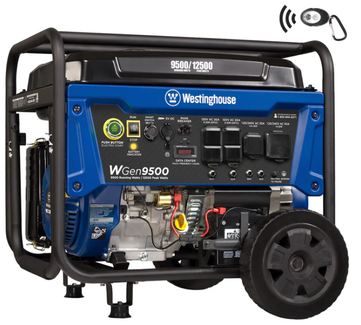
The Westinghouse WGen9500 is a powerful and versatile portable generator designed for home backup power, job sites, RVs, and outdoor events. It produces up to 12,500 peak watts and 9,500 running watts, ensuring you have the power you need when you need it most. With features like remote electric start, push-button ignition, and a durable 457cc 4-stroke OHV engine, the WGen9500 offers convenience, reliability, and long-lasting performance. The price of the Westinghouse Portable Generator WGen9500 is $999.00.
UNPACKING
|
Always have assistance when lifting the generator. The generator is heavy; lifting it could cause bodily harm. |
Avoid cuttingon or near staples to prevent personal injury. |
Tools required box cutter or similar device.
- Carefully cut the packing tape on top of the carton.
- Remove the Wheel Kit Accessories cardboard box.
- Carefully cut two sides of the carton to remove the generator.
WHAT COMES IN THE BOX
- Manual
- Quick Start Guide/Maintenance Schedule
- Wireless Remote Starter (1)
- 1.1 Liter Bottle of SAE 10W30 Oil (1)
- Spark Plug Socket Wrench (1)
- 11W Battery Charger, (14V .8A output) (1)
- Wheel Kit Accessories Box Funnel (1)
WHEEL KIT ACCESSORIES BOX
Open the Wheel Kit Accessories box and verify the contents against the list right. If any parts are missing, please locate an authorized Westinghouse Generator dealer

Wheel and Feet Kit Hardware

- Washer (2 used)
- Flange Bolt M8 x16mm (4 used)
- Hairpin Cotter Pin (2 used)
- Wheel Axle Pin (2)
FEATURES
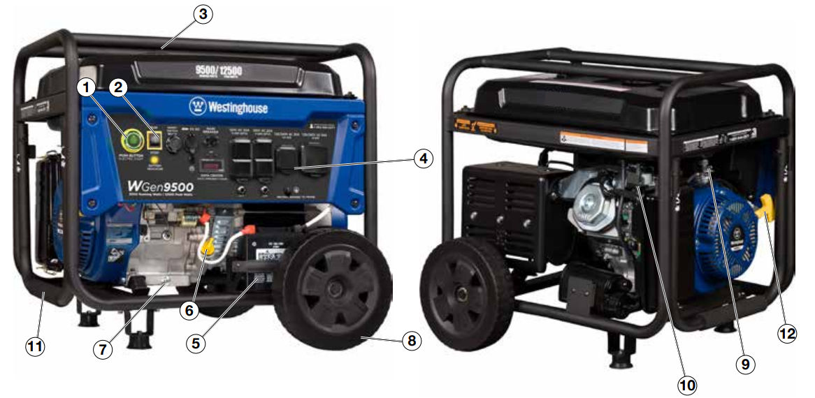
- Push Button Electric Start: Starts and stops the engine.
- Engine Control Switch/Battery Disconnect: Allows fuel to flow to engine and energizes the ignition system. Also, disconnects battery power when in “Stop” position.
- Fuel Cap: Close until clicking sound is heard.
- Control Panel: Contains the circuit breakers and outlets.
- Battery: Included for electric start models.
- Oil Fill Plug/Dipstick: Must be removed to add and check oil.
- Oil Drain Plug: Must be removed to drain engine oil
- Never Flat Wheels: For easy portability
- Fuel Shut off Valve: Controls the flow of fuel to the engine.
- Auto Choke: Battery must be hooked up for auto choke to work properly. You can manually adjust the choke if the battery is not connected.
- Single Piece Handle: Includes rubber grip. Allows you to easily push or pull unit with one hand.
- Recoil Start: Used to manually start the generator.
- Fuel Gauge: Indicates fuel level.
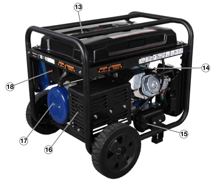
- Spark Plug Boot (Wire): Must be removed when servicing the engine or the spark plug.
- CARB Canister: Required for models sold into and used in California.
- Muffler and Spark Arrester: Avoid contact until engine is cooled down. Spark arrestor prevents sparks from exiting the muffler. It must be removed for servicing.
- Alternator Cover: Gain access to alternator wiring.
- Remote Start Pairing Button: Initiates the remote key fob pairing function.
CONTROL PANEL FEATURES
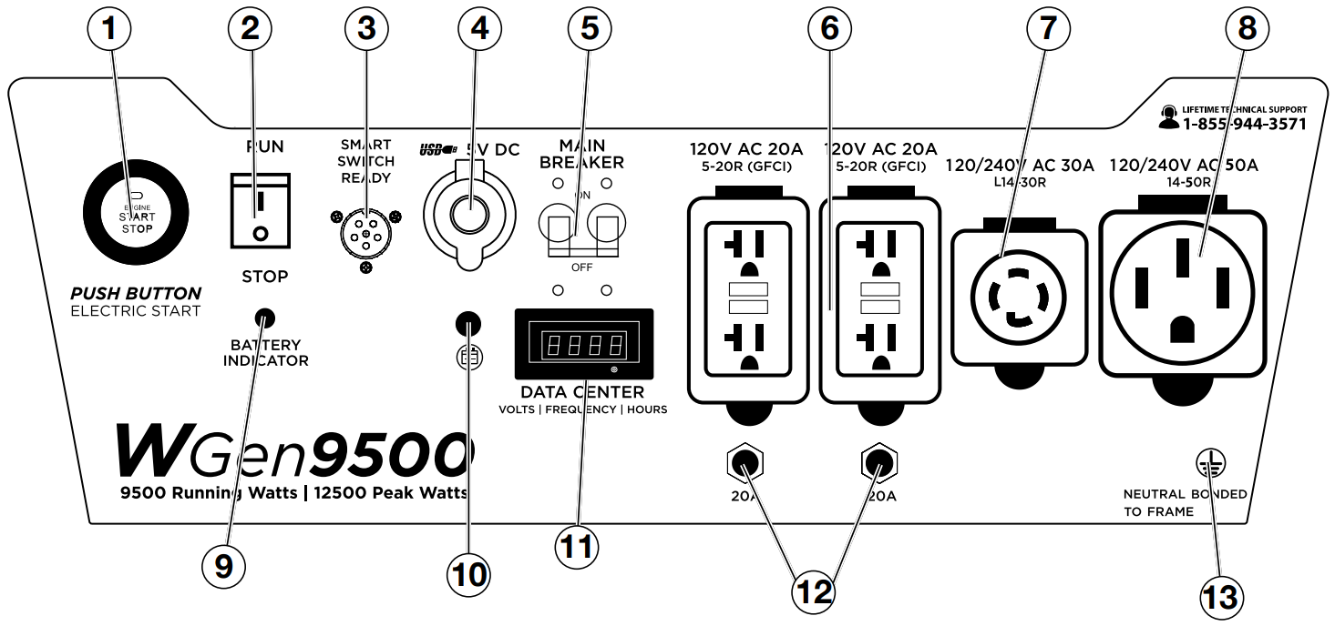
- Push Button Electric Start:
- Push for 1 second to automatically start the engine.
- Push again to stop the engine.
- Engine Control Switch/Battery Disconnect: Switch to “Stop” to stop the engine. When in “Stop” position it prevents the unit from drawing power from the battery. Switch to “Run” before starting engine.
- Smart Switch Outlet: Connects the Westinghouse ST Switch (sold separately) to the control panel.
- 5V USB Ports: 5V DC that come in 1 amp and 2.1 amps.
- Main Circuit Breaker: The main circuit breaker controls total output of all outlets to protect the generator.
- 120-Volt, 20-Amp Duplex GFCI Outlets (NEMA 5-20R): Each outlet is capable of carrying a maximum of 20 amps on a single receptacle or a combination of both receptacles.
- 120/240-Volt, 30-Amp Twist Lock Outlet (NEMA L14-30R): Outlet can supply either 120V or 240V output up to 30A.
- 120/240-Volt, 50-Amp Outlet (NEMA 14-50R): Outlet can supply either 120V or 240V up to 50 amps.
- Battery Indicator Light: When light is illuminated, the battery is connected and providing power to the electronics.
- Battery Charge Port: Engine control switch must be in OFF position to charge with included charger.
VFT Data Center: Press and release the mode button to toggle between Voltage, Frequency, Total Hour Meter and Run/Maintenance Timer.
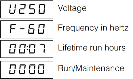
The Run/Maintenance Timer displays the time in hours and minutes each time the generator is ran. The run timer resets to 00:00 when the generator is shut off. Built into this run timer is a maintenance reminder. When the new generator is ran for 25 hours, the meter will display P25. This is to remind you to change the oil after the initial 25 hours of run time. When it displays P50, it is time to clean the air filter. When it displays P100 it is time change/clean the fuel filter, clean the air filter, and change the oil.
- 20-Amp Circuit Breakers: Each circuit breaker limits the current that can be delivered through the 120-volt duplex outlets to 20amps.
- Ground Terminal: The ground terminal is used to ground the generator.
WGen9500 Specifications
- Gasoline Running Watts
9500 - Gasoline Peak Watts
12500 - Running Amps
79A @ 120V
39.5A @ 240V - Peak Amps
104A @ 120V
52A @ 240V - AC Voltage
120/240 Volts - DC Voltage
5 Volts - AC Frequency
60 Hz - Parallel Capable
No - Engine Horse Power (HP)
13.5 HP - Total Harmonic Distortion (THD)
<23% - Automatic Voltage Regulator (AVR)
Yes - Low Idle Control
Yes - Starting System
Electric, Remote, Recoil - Battery Included
Yes - Battery Charger Included
Yes - Remote Start Fob Included
Yes (factory paired) - Remote Start Distance (yards/meters)
109 yd. (100 m.) - Push Button Start
Yes - Mobile App Compatible
No - Engine Displacement
457cc - Engine Brand
Westinghouse - Engine Type
OHV 4 Stroke - Engine RPM
3600 - Operational Volume
As low as 74 dBA - Spark Plug (included)
Torch F7TC - Carburetor Kit Required to Operate at Altitude
Yes - Altitude Carburetor Kit Number (sold separately)
140548 - Engine Lubrication
Splash - Recommended Oil
SAE 10W30 - Oil Bottle Size (included)
1.1 qt. (37.2 oz.) - Oil Capacity (Quarts/Ounces)
1.1 qt. (37.2 oz.) - Low Oil Shutdown
Automatic - Fuel Type
Unleaded Gasoline, 10% Ethanol or less - Fuel Shut Off
Manual - Fuel Tank Material
Steel - Fuel Tank Capacity (Gallons/Liters)
6.6 gal. (25 L) - Run Time at 25% Load (hrs.)
17.5 hrs. - Run Time at 50% Load (hrs.)
12 hrs. - Gasoline Fuel Gauge
Yes - Choke Type
Automatic - AC Outlets
(2) Duplex 120V 20A (5-20R), (1) 120V 30A (L5-30R), (1) 120/240V 30A (L14-30R) - DC Outlets
(2) 5V USB ports - Ground
Neutral Bonded to Frame - Covered Outlets
Yes - Transfer Switch Ready
Yes - Westinghouse Portable Transfer Switch Ready
Yes - Volts, Frequency, Lifetime Hour Meter
Yes - GFCI Outlets
No - OSHA Compliant
No - LED Data Center
No - RV Ready Outlet
Yes - Overload Protection (circuit breaker)
Yes - Handle
Yes - Emissions
EPA, CARB - Canada CSA Compliant
No - Heavy Duty Wheel Kit Included
Yes - Lift Hook Bracket
Yes - Muffler
Pulse-Flo™ - Spark Arrestor
Yes - Residential Warranty
3 Years - Commercial Warranty
1 Year - Assembled Length in. (mm)
27 in (687mm) - Assembled Width in. (mm)
22 in (555mm) - Assembled Height in. (mm)
22 in (567mm) - Carton Length in. (mm)
31 in (780mm) - Carton Width in. (mm)
22 in (570mm) - Carton Height in. (mm)
24 in (600mm) - Dry Unit Weight lb. (kg)
216 lb. (98kg) - Shipping Weight lb. (kg)
227 lb. (103kg) - UPC
853544008199 - GTIN
00853544008199
ASSEMBLY
INSTALLING WHEELS AND FEET
STOP: BEFORE ASSEMBLING THE GENERATOR.
|
Never lift the generator without assistance. The generator is heavy and lifting without assistance could result in personal injury. |
Never use the handles as a lifting point to support the entire weight of the generator. Only usethe handles to move the generator by lifting thehandles and using thewheels to movethe generator. |
Use caution when collapsing the handles. Handsand fingers couldget caught and pinched. |
NOTICE |
Assembling the generator will require lifting the unit on one side. Make sure all engine oil and fuel are drained from the unit prior to assembling. Once assembled, the wheel kit is not intended for on- road use. The wheel kit is designed for use on this generator only. |
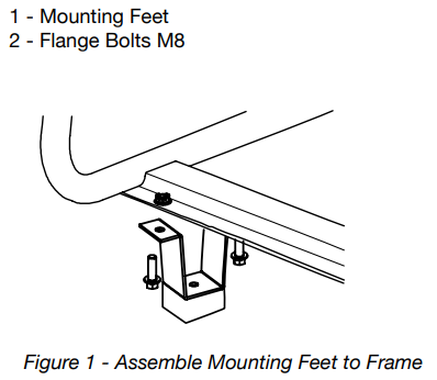
INSTALLING FEET TO FRAME
- Place generator on a flat surface.
- Place a piece of cardboard or other soft material to tip the generator onto, to protect the frame paint and prevent the generator from sliding. Tip the generator onto the side.
- Install the mounting feet to the frame using the M8 flange bolts included.
- Mounting Foot
Flange Bolts M8
INSTALLING WHEELS TO FRAME
Insert axle pin through washer and wheel.
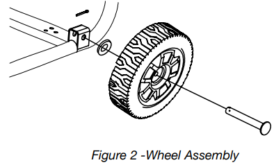
Install the wheel with axle pin through the axle bracket on the frame. The eye of the bolt should be facing toward the inside of the generator.
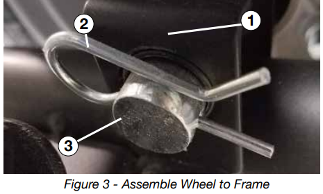
- Install the hairpin cotter through the axle pin to lock it in place.
- Axle Bracket
- Hairpin Clip
- Axle Pin
- Repeat previous steps on the other wheel.
CONNECTING THE BATTERY
WARNING
To avoid electric hock
- ALWAYS connect the positive (+) battery cable (red boot) first when connecting battery cables.
- ALWAYS disconnect the negative (-) battery cable (black boot) first when disconnecting battery cables.
- NEVER connect the negative (-) battery cable (black boot) to the positive (+) post on the battery.
- NEVER connect the positive (+) battery cable (red boot) to the negative (-) post on the battery.
- NEVER touch both battery posts simultaneously.
- NEVER place a metal tool across both battery posts.
- ALWAYS use insulated or nonconducting tools when installing the battery.
Using a screwdriver, remove the screw on the red positive (+) battery lead.
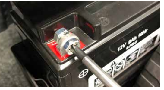
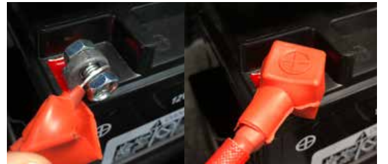
Securely tighten the positive (+) battery cable (red boot) to the positive (+) battery post. Make sure boot is over battery post.
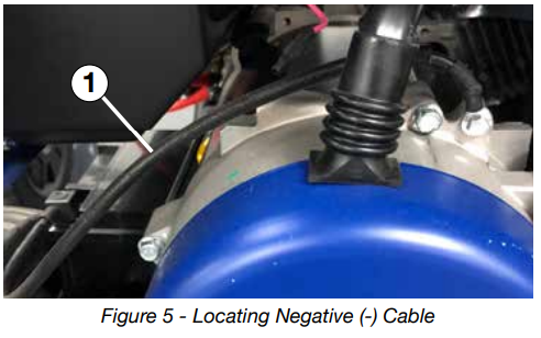
Locate the black negative (-) cable attached to the alternator case, route it to the negative (-) battery post. See Figure 5 below for location (1) of negative (-) cable.
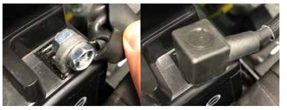
Remove the screw on the negative (-) battery post. Pull back the black boot and securely attach the negative (-) battery cable (black boot) to the negative (-) battery post and tighten screw. Replace the black boot so it protects the cable lug and battery post.
NOTICE
The electric start generator is equipped with a battery charging feature. Once the engine is running, a small charge is supplied to the battery via the battery cables and will slowly recharge the battery.
Description
The Westinghouse WGen9500 is designed to provide reliable power in various situations, from power outages to camping trips and construction sites. It is built with a durable steel frame and features a folding handle and never-flat wheels for easy transportation. The VFT Data Center displays voltage, frequency, and lifetime hours, ensuring that you always have the necessary information to maintain your generator. With its remote start feature, you can start or stop the generator from a distance, adding convenience to your power management.
OPERATION
BEFORE STARTING THE GENERATOR
STOP: BEFORE STARTING THE GENERATOR
Location Selection
Before starting the generator, avoid exhaust and location hazards by verifying:
- You have selected a location to operate the generator that is outdoors and well ventilated.
- You have selected a location with a level and solid surface on which to place the generator.
- You have selected a location that is at least 15 feet (4.5m) away from any building, other equipment or combustible material.
- If the generator is located close to a building, make sure it is not located near any windows, doors and/or vents.
DANGER |
| Using a generator indoors CAN KILL YOU IN MINUTES. Generator exhaust contains carbon monoxide. This is a poison vou cannot see or smell. |
NEVER use inside  Only use OUTSIDE  |
| Avold other generator hazards. READ MANUAL BEFORE USE. |
|
Always operate the generator on a level surface. Placing the generator on non level surfaces can cause the generator to tip over,causing fuel and oil to spill. Spilled fuel can ignite if it comesin contact with an ignition source such as a very hot surface. |
Do notoperate a deviceplugged into theUSB ports. Prolonged exposure to engine exhaust can cause serious injury or death. Whilecharging a device do not placeon the exhaustside of the generator. Extreme heat causedby exhaust candamage the device, and cause a potential fire hazard. |
NOTICE |
Only operate the generator on a solid, level surface. Operating the generator on a surface with loose material such as sand or grass clippings can cause debris to be ingested by the generator that could:
|
Weather
Never operate your generator outdoors during rain, snow or any combination of weather conditions that could lead to moisture collecting on, in or around the generator.
Dry Surface
Always operate the generator on a dry surface free of any moisture.
No Connected Loads
Make sure the generator has no connected loads before starting it. To ensure there are no connected loads, unplug any electrical extension cords that are plugged into the control panel receptacles.
NOTICE |
Starting thegenerator with loadsalready applied to it couldresult in damage to any appliance being powered off the generator during the brief start-up period. |
Grounding the Generator
The National Electric Code (NEC), as well as many local electrical codes, may require the generator to be connected to earth ground. The most common application that requires a ground rod is when you are using the generator as a separately derived system to provide back up power to your house. Typically this is when a transfer switch has a switched neutral.
As the generator application has many variables that cannot be determined by the manufacturer of the generator, a licensed electrician will need to determine if a grounding rod is needed. If a licensed electrician has determined the application requires a ground rod, make sure it is connected to earth ground by connecting the ground terminal on the control panel to earth ground using copper wire (minimum 10 AWG). Consult a qualified electrician for local grounding requirements.
Neutral Bonded: There is a permanent conduct between the generator (stator winding) and the frame.
|
Be sure the generator is properly connected to earth ground before operating. The generator must be grounded to prevent electrical shock due to faulty appliances. |
High Altitude Operation
Engine power is reduced the higher you operate above sea level. Output will be reduced by approximately 3.5% for every 1000ft of increased altitude from sea level. This is a natural occurrence and cannot be adjusted by engine. Increased exhaust emissions can also result due to increased fuel mixture. Other issues include hard starting, increased fuel consumption and spark plug fouling.
High Altitude Carburetor Kit Part Number: 140545
High Altitude DF Regulator Part Number: 140547
POWERCORD
Using Extension Cords
Westinghouse Portable Power assumes no responsibility for the content within this table. The use of this table is the responsibility of the user only. This table is intended for reference only. The results produced by using this table are not guaranteed to be correct or applicable in all situations as the type and construction of cords are highly variable. Always check with local regulations and a licensed electrician prior to installing or connecting an electrical appliance

Using Westinghouse Power Cord
Use the extension cord chart to determine the size of the conductor for extension cord applications. Determine the distance of the generator to the appliance on the top line of the chart. Then select the rated amperage of the generator on the left side of the chart. Where the two meet is the size of the conductor required for the application.
When using the WCG25/WCG20 power cord (sold separate) connect to the 120/240V outlet. The opposite end of the power cord is a fan tail receptacle with 2 green receptacles and 2 red receptacles. Each receptacle is rated at 120 volts AC. To balance the load on the generator’s alternator, use the red and green identifiers on the fan tail receptacle. To keep the load balanced, connect the loads so that both color receptacles are used. An example is one in red and one in green. Do not connect 2 in red and none in green, or 2 in green and none in red. If only one color receptacle is used with multiple loads, the alternator may experience an unbalanced load, causing undue vibration to generator.

CONNECTING THE GENERATOR TO A BUILDING ELECTRICAL SYSTEM
It is recommended to use a manual transfer switch when connecting directly to a buildings electrical system. Connecting a portable generator to a buildings electrical system must be made in strict compliance with all national and local electrical codes and laws, and be completed by a qualified electrician.
TRANSFER SWITCH CONNECTIONS
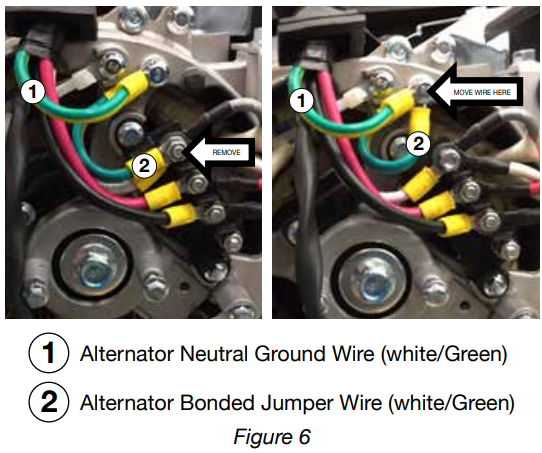
The Westinghouse generator is wired with the neutral bonded to ground. If you are connecting your generator to a panel board transfer switch, a licensed electrician will need to consider removing the bonded neutral to ensure proper operation of household GFCI circuits. Begin by removing the alternator cover (18 on page 14). Once the cover is off remove the nut that holds the bonded ground jumper wire (see “2” in Figure 6). Once the nut is removed take the bonded jumper wire off and re-secure the nut. Next, remove the screw holding the neutral ground wire (see “1” in Figure 6). Attach the bonded jumper wire (2) to the neutral ground (1) and tighten the screw.
If the bonded neutral is removed the generator must be relabeled as floating neutral on the control panel.
If your generator is equipped with GFCI receptacles, removing the bonded neutral may not allow proper operation of the GFCI receptacles. Always keep the jumper wire in case it is needed for future use when not connected to a transfer switch.
ADDING / CHECKING ENGINE FLUIDS AND FUEL
STOP: BEFORE ADDING/CHECKING ENGINE FLUIDS AND FUEL.
|
Filling the fuel tank with gasoline while the generator is running can cause gasoline to leak and come in contact with hot surfaces that can ignite the gasoline. |
Before starting the generator, always check the level of:
- Engine oil
- Gasoline in the fuel tank
Once the generator is started and the engine gets warm, it is not safe to add gasoline to the fuel tank or engine oil to the engine while the engine is running or the engine and muffler are hot.
CHECKING AND / OR ADDING ENGINE OIL
|
Internal pressure can build in the engine crankcase whilethe engine is running. Removing the oil fill plug/dipstick while the engine is hot can cause extremely hot oil to spray out of the crankcase and can severely burn skin. Allow engine oil to cool for several minutes before removing the oil fill plug/dipstick. |
The unit as shipped does not contain oil in the engine. You must add engine oil before starting the generator for the first time. See Checking Engine Oil and Adding Engine Oil on page 26 for instructions on checking engine oil level and the procedure for adding engine oil.
NOTICE |
The engine does not contain engine oil as shipped. Attempting to start the engine can damage engine components. The owner of the generator is responsible to ensure the proper oil level is maintained during the operation of the generator. Failure to maintain the proper oil level can result in engine damage. |
NOTICE |
During the first five hours of operating the generator make sure to notexceed 50% of the ratedrunning watts untilthe unit is broken in properly. Make sure to vary to load occasionally to allow stator windings to heat and cool. Adjusting the load will also help seat piston rings. Check oil more oftenduring the firstcouple times of operating the generator. |
NOTICE |
Weather will affect engine oil performance. Change the type of engine oil used based on weather conditions to suit the engine needs. |
STOP: ADDING GASOLINE TO THE FUEL TANK BEFORE ADDING GAS TO THE TANK.
|
Never refuel the generator while the engine is running. |
Always turn theengine off andallow the generator to cool before refueling. |
Required Gasoline
Only use gasoline that meets the following requirements:
- Unleaded gasoline only
- Gasoline with maximum 10% ethanol added
- Gasoline with an 87 octane rating or higher
Filling the Fuel Tank
Follow the steps below to fill the fuel tank:
- Shut off the generator.
- Allow the generator to cool down so all surface areas of the muffler and engine are cool to the touch.
- Move the generator to a flat surface.
- Clean area around the fuel cap.
- Remove the fuel cap by rotating counterclockwise.
- Slowly add gasoline into the fuel tank. Be very careful not to overfill the tank. The gasoline level should NOT be higher than the filler neck (see Figure 7).
- Install the fuel cap by rotating clockwise until you hear a click, indicating the cap is completely installed.

|
Avoid prolonged breathing of gasoline vapors. |
CONNECTING TO STANDARD LPG/PROPANE TANK
STOP: BEFORE CONNECTING PROPANE TANK TO THE GENERATOR.
Connecting LPG Tank
- Make sure the generator is off, on a flat surface in well ventilated area.
- Make sure propane tank valve is in the off position.
- Make sure the fuel selector switch on the generator control panel is pointing downward to “Propane”.
- Remove the plastic cover on the generator propane inlet valve.
Using your fingers tighten the LPG hose (included) end below to the generator propane inlet. DO NOT OVER-TIGHTEN 35-88 Ib-in maximum.
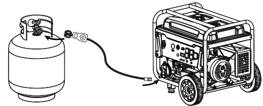
- Attach the other end of the hose to a tank of LPG/Propane and hand tighten.
- Check all connections for leaks by wetting the fittings with soapy water. Anywhere that bubbles appear or grow indicates a leak in the connection. If a leak exists at a fitting then turn off the tank valve and tighten the fitting. Turn the gas back on and recheck with soapy water again. If the leak continues or if the leak is not at a fitting then do not use the generator and contact customer service.
NOTICE
- When using standard 20 or 30 pound capacity LPG tanks, make sure they have Type 1, right hand Acme threads.
- Verify the requalification date on the tank has not expired.
- All new tanks must be purged of air and moisture prior to filling. Used tanks that have not been plugged or kept closed must also be purged
- The purging process should be done by a LPG supplier. (Tanks from an exchange supplier should have been purged and filled properly already)
- Always position the tank so the connection between the valve and the gas inlet won’t cause sharp bends or kinks in the hose.
|
Do not start generator if you smell propane. This may result in explosion hazard. Do not use provided LPG hose for any other appliances. Always turn off the propane tank and disconnect LPG hose when not in use. |
CONNECTING TO LARGE LPG/PROPANE TANK
You can hook up you Duel Fuel Generator to a large home LP tank. It is required that you consult a plumber to properly connect your generator to the tank.
To properly connect with a large propane tank you must first check and confirm the LP fuel pressure at the outlet of the LP tank. The LP fuel pressure should be 14-10” of water column, which is the standard fuel pressure for residential gas fired appliances.
If the LP fuel pressure is within the 14-10” water column range, the primary fuel regulator should be removed from the fuel line components. Then plumb directly from the LP tank to the secondary regulator assembled to the generator.
|
You must consult a certified plumber to connect to large LP tank safely.. |
BEFORE STARTING THE GENERATOR
Before attempting to start the generator, verify the following:
- The engine is filled with engine oil.
- The generator is situated in a proper location.
- The generator is on a dry surface.
- All loads are disconnected from the generator.
- The generator is properly grounded the Generator.
- Propane connection is secure with no leaks or damage. See Connecting LPG TanK.
DANGER |
Never use the generator in a location that is wet or damp. Never expose the generator to rain, snow, water spray or standing water while in use. Protect the generator from all hazardous weather conditions. Moisture or ice can cause a short circuit or other malfunction in the electrical circuit. |
Never operate the generator in an enclosed area. Engine exhaust contains carbon monoxide. Only operate the generator outside and away from windows, doors and vents. |
NOTICE |
The engine is equipped with a low oil shutdown switch. If the oil level becomes low, the engine may shut down and not start until the oilis filled to the properlevel. Poor oilquality may interfere with the operation of the low oil shutdown switch.
The owner of the generator is responsible to ensure the proper oil level is maintained during the operation of the generator. Failure to maintain the proper oil level can result in engine damage. |
NOTICE |
When operating on LPG it is commonfor frost to form on the tank and regulators. This is notan indication of a problem. The amount of frostthat forms can be affected by the size of the container, the amount of fuel being used, the humidity of the air and other operating conditions. In standard use this frost may reduce flow of gas and lower performance. If frost becomes an issue try exchanging fuel tanks to allow thefirst tank to warm up.You can also temporarily warm the tank up by pouring warm water overthe top of the propane tank. |
SWITCHING FUEL SOURCES
The below assumes that the propane fuel line is already attached to the generator securely and safely.
While the unit is running simply turn the FUEL SELECTOR knob to the desired fuel source. If you want to switch from gasoline to propane make sure the propane tank valve is open before you switch. When you move from propane to gasoline shut the propane valve after you have switched to gas.
NOTICE |
If youdo not planon operating theunit on propane do not leave the propane tank valve open. When starting on propane the engine may run roughfor a few seconds while it purges gasoline in the carburetor. If the engine failswhen switching fuel sources simplyrestart the unit on the fuel source that you switched to. |
PROGRAMMING THE GENERATOR FOR REMOTE START
NOTICE |
The key fob included with the generator should come alreadypaired with the unit.If it does not you can followthe directions belowto reconnect. If your unit was shipped withouta key fob please contact our customer support team. |
|
Always make sure the area around the generator is clear of bystanders beforeusing the remotestart to start the generator. |
If you are runninggenerator on Propanethe generator cannot be stopped with remote start key fob. |
The generator can be started remotely from up to a maximum of 109 yards (100 M) away using the remote start key fob with new, fully charged batteries in the key fob. As the batteries’ state of charge in the key fob reduces, the distance to start the generator will also reduce.
Before the generator can be started, an initial start-up procedure must be performed so the generator and the key fob recognize each other. If the key fob is replaced, you will need to go through this procedure with the new fob.
- With the battery connected, turn the engine control switch to the RUN position. The yellow battery light will illuminate.
- Push and hold the red REMOTE PAIRING button on the side of the control panel until the push button start (3) on the control panel illuminates red, then let go (see 17 on page 13 for location of button).
- Press and hold the STOP (2) button on the remote start key fob until the red light on the push button start (3) goes out, then let go.
- Press and hold the START (1) button on the remote start key fob until the red light on the push button start (3) goes out, then let go.
Press and hold the REMOTE PAIRING button until the red light on the push button start (3) goes out. The generator is now programmed to start remotely.
POWER OUTPUT AND DEMAND
The generator should not be run completely unloaded for extended periods otherwise the engine may be damaged. It is recommended that the generator should always be operated with at least one-third of its rated 120-Volt AC power output. 120-Volt AC devices have two different electric power demands that must be taken into consideration, namely the running power and the starting/peak power. Both are measured in Watts (typically abbreviated as “W”).
The steady state continuous load is the running power demand and this is often marked on the device near its model number or serial number. Sometimes the device might only be marked with its voltage (i.e. 120 V) and current draw (e.g. 6 Amp or 6 A), in which case the running power demand in Watts can be obtained by multiplying the voltage times the current, e.g. 120 V × 20 A = 2,400 W.
Simple resistive 120-Volt AC devices such as incandescent bulbs, toasters, heaters, etc. have no extra power demand when starting, and so their starting power demands are the same as their running power demands.
More complex120-Volt AC devices containing inductive or capacitive elements such as electric motors have a momentary extra power demand when starting, which can be up to seven times the running power demand or more. Manufacturers of such devices rarely publish this starting power demand and so it’s often necessary to estimate it. A rule of thumb for devices fitted with an electric motor is to apply a starting power multiplier of 1.2 for small hand-held or portable devices and a value of 3.5 for larger stationary devices.
For example, a 900 W angle grinder can be assumed to have a starting power demand of at least 1.2 × 900 W, which equals 1,080 W. Similarly, a 1,650 W air compressor can be assumed to have a starting power demand of at least 3.5 × 1,650 W, which equals 5,775 W.
To prevent overloading of the generator’s 120-Volt AC system:
- Add up the running power demand of all the 120-Volt AC devices that will be connected to the generator at one time. This total must not be greater than the generator’s specified running power output.
- Add up the running power demand again, but for the largest motor-driven device use the value of its starting power demand instead of its running power demand. This total must not be greater than the generator’s specified starting power output.
- The total running power demand of all the devices that will be connected to any one of the generator’s outlets must not exceed the generator’s specified running power output or 3,700 W, whichever is the lesser.
ELECTRIC START
Be sure to check oil levels before starting. If it is the first time starting make sure to add oil (see Adding Engine Oil page 26).
- Make sure nothing is plugged into power outlets
- Verify the battery is properly installed and both battery cables are attached
Make sure the circuit breakers are properly set (see Figure 8).
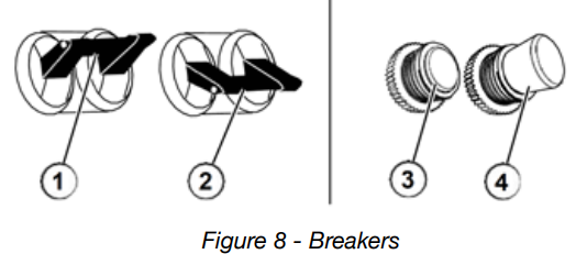
- 240/120VMain Circuit Breaker Operating Position
- 240/120V Main Circuit Breaker Tripped Position
- 120V Circuit Breaker Operating Position
- 120V Circuit Breaker Tripped Position
- Select fuel source for start up:
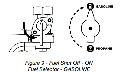
- FOR GASOLINE:
- Move the fuel shut off valve to the ON position (see Figure 9).
Turn fuel selector knob to GASOLINE (see Figure 9).
- FOR LPG/PROPANE:
- Make sure the LPG hose is safely secured from the generator to the tank.
Turn the fuel selector knob to PROPANE (see Figure 10).
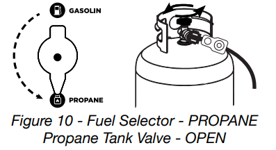
- Fully open the valve on the propane tank.
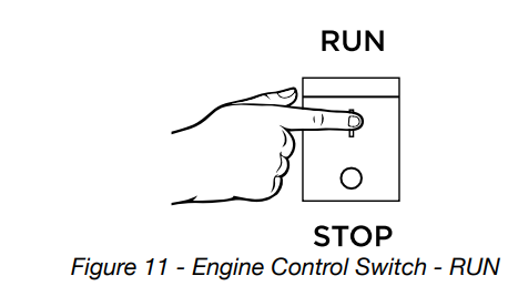
- FOR GASOLINE:
Push the engine control switch into the RUN position
Push and hold the push button start until the generator starts, then release. If using remote start then hold down START on the remote key fob until the generator starts, then release.
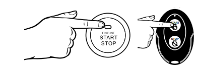
The engine will automatically set the choke and begin the start sequence.
- If the engine has started successfully the light indicator on the engine start button will turn green.
- If the engine fails to start, the generator controls will attempt to start the engine two more times for a total of three attempts.
- If the third attempt fails, the light on the engine start button will turn red.
- If the engine has failed to start after three attempts the push button start can be pushed again to begin the automatic start sequence.
- The engine control switch can be switched at any time during the automatic start sequence to abort the engine start attempt.
NOTE: If the cranking speed drops after each unsuccessful attempt, then the battery may not be adequately charged. You can alternatively start the generator using the recoil start as instructed in Manually Starting a Generator.
MANUALLY STARTING THE GENERATOR
Be sure to check oil levels before starting. If it is the first time starting make sure to add oil.
- Make sure nothing is plugged into power outlets
- Make sure the circuit breakers are properly set (see Figure 8)
- Select fuel source.
- Push the engine control switch into the RUN position (see Figure 11).
- Manually set the choke:
Cold Start: Close the choke by moving it right towards the front handle of the generator.
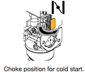
Warm Start: Open the choke by moving it left towards the wheels of the generator.

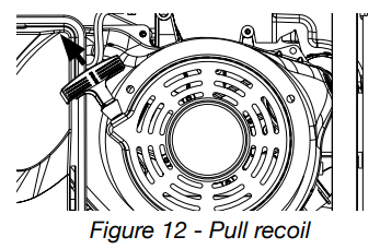
Firmly grasp and pull the recoil handle slowly until you feel increased resistance. At this point, apply a rapid pull while pulling up and slightly away from the generator (see Figure 12).
- Plug-in electric devices.
STOPPING THE GENERATOR
Normal Operation
During normal operation, use the following steps to stop your generator:
- Remove any connected loads from the control panel receptacles.
- Allow the generator to run at “no load” to reduce and stabilize engine and alternator temperatures.
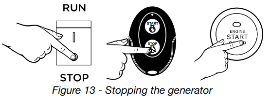
- Choose from options below to stop the generator (see Figure 13):
- Position the engine control switch to STOP
- Hold push button start until the generator stops
- Hold the STOP button on the remote start key fob (Note: The generator will run for an additional 15 seconds as it goes through a cool down cycle before shutting off.)
NOTE If you plan to store the generator after use, stop the generator by turning the fuel shutoff valve to the OFF position and allow the fuel to be consumed from the carburetor.
- If running off of propane then close the propane valve. If running on gas turn the fuel shutoff valve to the OFF position.
During an Emergency
If there is an emergency and the generator must be stopped quickly, position the engine control switch to the STOP position immediately.
Setup Guide
To operate the Westinghouse Portable Generator WGen9500, follow these steps:
- Place the generator on a level surface and ensure that it is at least 5 feet away from any building openings.
- Turn the fuel valve to the "ON" position and check the oil level. If necessary, add oil using the recommended type.
- Connect the appliances or tools you want to power to the generator's outlets.
- Turn on the main breaker and press the electric start button or use the remote start key fob to start the generator.
- Monitor the generator's performance and adjust the load as needed.
TROUBLESHOOTING
PROBLEM | POTENTIAL CAUSE | SOLUTION |
Engine is running, but no electrical output | 1. Circuit breakers are tripped. | 1. Resetthe circuit breakers and check for overload condition. |
2. The power cord’splug connector is not fully engaged in the generator’s outlet. | 2. Verifyplug connector is firmly engaged in the generator’s outlet. If using the 240V outlet, make sure plug connector is rotated 1/4 turn in the clockwise direction. | |
3. Faulty or defective power cord | 3. Replace power cord. | |
4. Faulty or defective electrical appliance | 4. Try connecting a known good appliance to verify the generator is producing electrical power. | |
5. GFCI outletis tripped | 5. Press the reset buttonon the GFCI outlet. | |
6. If trying1-5 above doesnot solve the problem, the cause might be the generator has a fault. | 6. Take the generator to your nearest authorized service dealer. |
Engine will not start or remain running while trying to start. | 1. Fuel shutoff valve isinthe OFF position. | 1. Move the fuel shutoffvalve to the ON position. |
2. Generator is out of gasoline. | 2. Add gasoline to the generator. | |
3. Fuel flowis obstructed. | 3. Inspect and clean fueldelivery passages. | |
4. Starting battery may have insufficient charge | 4. On electric startmodels only. Check battery output and charge battery as necessary. | |
5. Dirty air filter | 5. Check andclean the air filter. | |
6. Lowoil level shutdown switch is preventing the unit from starting. | 6. Checkoil level and add oil if necessary. | |
7. Sparkplug boot is not fullyengaged with the spark plug tip. | 7. Firmly push down on the spark plug boot to ensurethe boot is fully engaged | |
8. Spark plug is faulty. | 8. Removeand check the spark plug. Replace if faulty. | |
9. Dirty/plugged spark arrestor | 9. Check andclean the sparkarrestor. | |
10. Stalefuel | 10. Drainfuel and replace with fresh fuel. | |
11. If trying 1-11 above does not solve the problem, the cause might be the generator has a fault. | 11. Take the generator to your nearest authorized service dealer. |
Generator suddenly stops running. | 1. Generator is out of fuel. | 1. Check fuel level. Add fuel if necessary. |
2. The low oil shut down switch has stopped the engine. | 2. Checkoil level and add oil if necessary. | |
3. Too much load | 3. Restart the generator and reduce the load. | |
4. If trying 1-3 above does not solve the problem,the cause might be a fault in the generator. | 4. Take the generator to your nearest authorized service dealer. |
Engine runs erratic; doesnot hold a steady RPM. | 1. Dirty air filter | 1. Clean the air filter. |
2. Applied loads maybe cycling on and off | 2. As applied loads cycle, changes in engine speedmay occur; this is a normal condition. | |
3. If trying 1-3 above does not solve the problem, the cause might be a fault in the generator | 3. Take the generator to your nearest authorized service dealer. |
SCHEMATIC
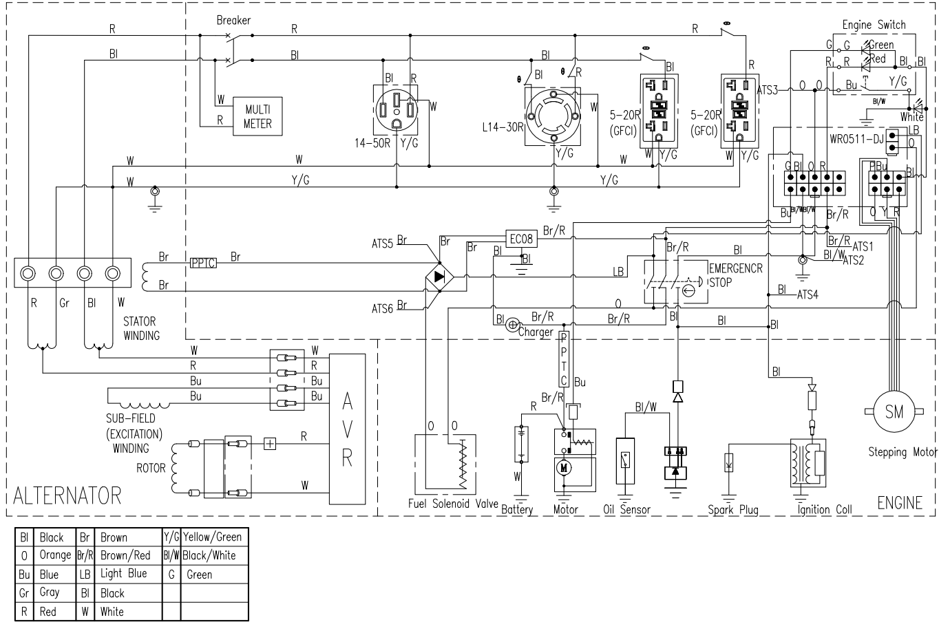
| Y/G Yellow/Green | Bl/Wh Black/White | |||
|---|---|---|---|---|
| Y/G | G Green | |||
| Br Brown | Br | |||
| O Orange | Br/R Brown/Red | LB Light Blue | ||
| Bl Black | Bl | Bl Black | W White | |
| O | O | Bu Blue | Gr Gray | |
| Bu | Gr | R Red |
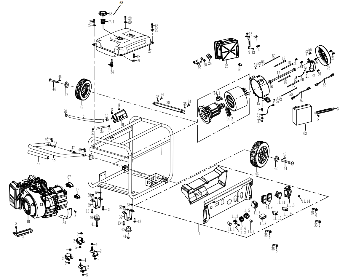
EXPLODED VIEW
| Item Number | Description |
|---|---|
| 210004 | GENERATOR COVER |
| 210003 | WGC25 25' POWER CORD |
| 210052 | 30A 6 BREAKER TRANSFER SWITCH KIT - MODEL WHMTS30 |
| 210075 | 25' CORD 30AMP TRANSFER SWITCH |
| 210076 | 50A 6 BREAKER TRANSFER SWITCH KIT - MODEL WHMTS50 |
| 210051 | 25' CORD 50AMP TRANSFER SWITCH |
| 130573 | 25' L14-50R EXTENSION CORD (120/240-V, 50A OUTLET) |
EXPLODED VIEW PART NO.
No. | Part. | DESCRIPTION |
| 1 | 300654 | FRAME |
| 2 | 100552 | ISOLATOR B |
| 3 | 100558 | BATTERY HOLDER |
| 4 | 100551 | NUT M10 |
| 5 | 180524 | NUT M8 |
| 6 | 150507 | CONNECTING PIPE |
| 7 | 180563 | BRACKET, AIR CLEANER |
| 8 | 120505 | BOLT M6X12 |
| 9 | 110504 | MUFFLER BRACKET |
| 10 | 300655 | ENGINE ASSY |
| 11 | 300656 | PANEL COMP |
| 11.1 | 130528 | PUSH BUTTONSTART SWITCH |
| 11.2 | 300723 | INDICATOR LIGHT |
| 11.3 | 130534 | START STOPSWITCH |
| 11.4 | 190209 | SMART SWITCH |
| 11.5 | 130569 | DOUBLE USBSOCKET |
| 11.6 | 130566 | BATTERY CHARGING PORT 2.5MM |
| 11.7 | 130504 | CIRCUIT BREAKER 30/2P/23A |
| 11.8 | 130503 | VFT METER |
| 11.9 | 130563 | DOUBLE SOCKET. 5-20R/UL |
| 11.10 | 130507 | THERMAL PROTECTOR 30/1P/20A |
| 11.11 | 130573 | THE SOCKET14-30R/UL |
| 11.12 | 130568 | THERMAL PROTECTOR 30A |
| 11.13 | 130505 | SOCKET L14-30R/UL |
| 11.14 | 300674 | GROUNDING TERMINAL COMPONENT |
| 12 | 100726 | RUBBER DUST COVER |
| 13 | 100516 | BOLT M8×16 |
| 14 | 300658 | ALTERNATOR ASSEMBLY |
| 15 | 120504 | REAR BEARING CARRIER |
| 16 | 100540 | GASKET, ROTOR BOLT M10.5XM30X4 |
| 17 | 120514 | BOLT M10X1.25X255 |
| 18 | 120513 | BOLT M6X200 |
| 19 | 150508 | CLIP, FUEL LINE M9X0.8 |
| 20 | 140539 | CLIP, FUEL LINE M10 |
| 21 | 120537 | BOLT M5×12 |
| 22 | 120517A | AVR |
| 23 | 120519 | END COVER |
| 24 | 110501 | EXHAUST PIPE GASKET |
| 25 | 110502 | SPRING WASHERM8 |
| 26 | 110500 | MUFFLER COMP |
| 27 | 150555 | FUEL TANK ASSEMBLY |
| 27.1 | 230514 | FUEL GAUGE |
| 28 | 120541 | BOLT M6X25 |
| 29 | 150501 | WASHER FUEL TANK |
| 30 | 150512 | CARBON TANK COMP |
| 31 | 120542 | GROUNDING WIRE |
| 32 | 120508 | TOOTH TYPE GASKET M8 |
| 33 | 150505 | FUEL TANK CAP COMP |
| 34 | 150502 | FUEL COCK |
| 35 | 100547 | WASHER |
| 36 | 150510 | CONNECTING PIPE |
| 37 | 120506 | NUT M6 |
| 38 | 100581 | FUEL TANK BRACKET |
| 39 | 100512 | FOOT BRACKET |
| 40 | 100515 | VIBRATION ISOLATION PAD |
| 41 | 100582 | BOLT M6X28 |
| 42 | 100510 | FLAT WASHERM13XM37X4 |
| 43 | 100506 | WHEEL |
| 44 | 100504 | AXLE |
| 45 | 100508 | COTTER PIN |
| 46 | 100527 | PLUG, HANDLE |
| 47 | 100525 | BOLT, HANDLEM10XM12.5X53.5 |
| 48 | 100521 | HANDLE ASSEMBLY |
| 49 | 100523 | RUBBER, HANDLE |
| 50 | 120509 | BOLT M5X230 |
| 51 | 120510 | NUT M5 |
| 52 | 120511 | FLAT WASHERM5 |
| 53 | 120512 | SPRING WASHER M5 |
| 54 | 180561 | GUARD COVER,CRANKCASE |
| 55 | 110503 | BOLT M8X30 |
| 56 | 120518 | BOLT M5X16 |
| 57 | 140508 | FUEL LINE CLAMP |
| 58 | 100520 | NUT M8 |
| 59 | 120506 | LOCK NUT M6 |
| 60 | 120516 | GROUNDING WIRE |
| 61 | 100555 | NEGATIVE LEAD |
| 62 | 100556 | POSITIVE LEAD |
| 63 | 100557 | BATTERY |
| 64 | 130536 | BOLT M6X16 |
| 65 | 190699 | TOOTH WASHER M5 |
| 66 | 300659 | Q TYPE CLIP |
| 67 | 100716 | DUSTPROOF SHEET |
| 68 | 230514 | FUEL GAGE |
| - | 230523 | 1.1L Oil Bottle |
| - | 130172 | Remote Key Fob |
ENGINE VIEW
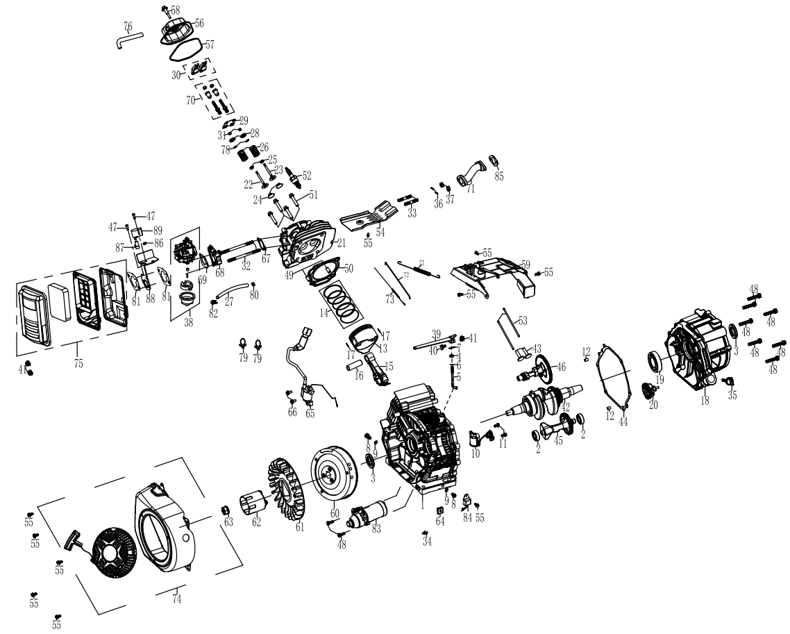
ENGINE VIEW PART NO.
NO. | PART. | DESCRIPTION |
1 | 300660 | CRANKCASE |
2 | 180593 | BALL BEARING |
3 | 180504 | OIL SEAL |
4 | 180411 | SEAL, GOVERNORARM SHAFT |
5 | 180410 | SHAFT, GOVERNOR ARM |
6 | 190409 | WASHER, GOVERNOR ARM SHAFT |
7 | 190408 | PIN, LOCK |
8 | 180507 | BOLT DRAIN PLUG |
9 | 180508 | WASHER, DRAINPLUG |
10 | 180586 | SWITCH ASSEMBLY, OIL LEVEL |
11 | 130536 | BOLT M6X16 |
12 | 180604 | DOWEL PIN, CASECOVER |
13 | 180787 | PISTON |
14 | 180788 | SCRAPER RING SET, PISTON |
15 | 180789 | ROD ASSEMBLY., CONNECTING |
16 | 180790 | PIN, PISTON |
17 | 180791 | CLIP, PISTON |
18 | 180792 | COVER ASSEMBLY, CRANKCASE |
19 | 180530 | BALL BEARING |
20 | 300661 | GOVERNOR ASSEMBLY |
21 | 180793 | CYLINDER HEAD |
22 | 180794 | VALVE, IN |
23 | 180795 | VALVE EXHAUST |
24 | 180752 | RETURNER, INTAKEVALVE |
25 | 180753 | OIL SEAL,VALVE |
26 | 190224 | SPRING, VALVE |
27 | 180797 | FUEL LINE |
28 | 180755 | SEAT, VALVESPRING, EX |
29 | 180798 | PLATE,PUSH ROD GUIDE |
30 | 180799 | ROCKER ASSY |
31 | 180756 | ROTATOR |
32 | 140503 | BOLT, STUD |
33 | 180571 | BOLT M8X38 |
34 | 300662 | CLIP |
35 | 180531 | DIPSTICK |
36 | 110502 | SPRING WASHER |
| 37 | 180524 | NUT M8 |
| 38 | 300663 | CARBURETOR ASSEMBLY |
| 39 | 180515 | GOVERNOR ARM |
| 40 | 300075 | BOLT, GOVERNOR ARM |
| 41 | 120506 | NUT M6 |
| 42 | 300664 | CRANKSHAFT ASSEMBLY |
43 | 180803 | LIFTER, VALVE |
44 | 180804 | PACKING, CASECOVER |
45 | 180805 | BALANCING SHAFT |
46 | 180806 | CAMSHAFT ASSEMBLY |
47 | 140558 | SCREW M4X8 |
48 | 180808 | BOLT M8X40 |
49 | 180742 | PIN DOWEL |
50 | 180809 | GASKET, CYLINDER HEAD |
51 | 180523 | BOLT M10X80 |
52 | 180526 | SPARK PLUG |
53 | 180810 | ROD, PUSH |
54 | 180811 | SHROUD |
55 | 120505 | BOLT M6X12 |
56 | 180527 | COVER COMP,CYLINDER HEAD |
57 | 180528 | PACKING, HEADCOVER |
58 | 180529 | LOCK BOLT |
59 | 180812 | SHROUD ASSY, UPPER |
60 | 300665 | FLYWHEEL ASSEMBLY |
61 | 180502 | FAN,RECOIL STARTER |
62 | 180501 | PULLEY,STARTER |
63 | 180500 | NUT FLYWHEEL |
64 | 180510 | RUBBER STARTERASSY |
65 | 180505 | IGNITION COIL ASSY |
66 | 100518 | BOLT M6X25 |
67 | 140504 | PACKING, INTAKE |
68 | 140502 | INSULATOR, CARBURETOR |
69 | 140509 | PACKING, CARBURETOR |
70 | 180636 | ADJUSTER ROCKERARM |
71 | 180521 | EXHAUST PIPE |
72 | 180516 | ROD, GOVERNOR |
73 | 180517 | SPRING, THROTTLERETURN |
74 | 300666 | RECOIL STARTERASSEMBLY |
75 | 160514 | AIR CLEANERASSEMBLY |
76 | 180533 | TUBE, BREATHER |
| 77 | 300667 | SPRING, GOVERNOR |
| 78 | 180744 | LOCKING FLAPS |
| 79 | 170502 | CLIP |
| 80 | 140506 | RUBBER, FUEL |
| 81 | 140537 | GASKET, AIR CLEANER |
| 82 | 140508 | CLIP, FUEL LINE |
| 83 | 170503 | STARTING MOTORASSEMBLY |
84 | 180509 | AMPLIFIER |
85 | 110501 | EXHAUST PIPE GASKET |
86 | 300500 | SPRING |
87 | 140557 | STEP MOTOR DRIVE SHAFT |
88 | 190192 | BRACKET, STEPPER MOTOR |
89 | 190217 | STEPPER MOTOR |
- | 140548 | HIGH ALTITUDE CARBURETOR ASSY (SOLD SEPARATE) |
- | m07500 | MAINTENANCE KIT(SOLD SEPARATE) |
- | 170040 | STARTING SOLENOID |
- | 300504 | SPARK ARRESTOR |
Westinghouse Portable Generator WGen9500 Pros & Cons
Pros
- High running and peak wattage
- Long run time
- Remote start feature
- Durable construction
Cons
- Heavier than some competitors
- Noise level is relatively high compared to some generators
Customer Reviews
Customers have praised the Westinghouse Portable Generator WGen9500 for its power, long run time, and convenient remote start feature. Common complaints include the generator's weight and noise level.
Faqs
What is the weight of the Portable Generator?
What type of oil should be used in the WGen9500?
What is the noise level of the Westinghouse?
How long can the WGen9500 run on a full tank of gas?
What is the warranty period for the Westinghouse WGen9500?
How do I maintain the Westinghouse Portable Generator?
What is the recommended break-in procedure for the Westinghouse?
Can the Westinghouse WGen9500 be used in the rain?
Can the Westinghouse power a whole house?
Leave a Comment