Wfco Power Center Fuse & Breaker WF-8975 User Manual
Content
Introduction
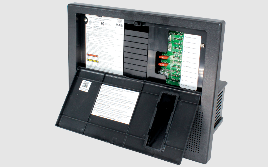
The WFCO Power Center Fuse & Breaker WF-8975 is an essential component for RV owners and mobile applications, providing reliable power management and circuit protection. Designed to accommodate various electrical needs, this unit features multiple circuit breakers and fuses to ensure safety and efficiency. Its compact design allows for easy installation in tight spaces, making it a practical choice for enhancing your vehicle's electrical system. The WF-8975 is priced at approximately $89.99, offering great value for dependable power solutions.
Back Side
Specifications
| Parameter | WF-8935 | WF-8945 | WF-8955 | WF-8965 | WF-8975 |
|---|---|---|---|---|---|
| Model No. | |||||
| Converter Input Power: | |||||
| Voltage: | 105-130VAC | 105-130VAC | 105-130VAC | 105-130VAC | 105-130VAC |
| Frequency: | 60Hz | 60Hz | 60Hz | 60Hz | 60Hz |
| Max. input current @ 105Vac | 7A | 9A | 11A | 13A | 15A |
| Max Power | 600 Watt | 770 Watt | 940 Watt | 1110 Watt | 1280 Watt |
| Converter Output Power | |||||
| Continuous power: | 475 Watt | 610 Watt | 750 Watt | 880 Watt | 1020 Watt |
| Rated DC Output Voltage | 13.6V | 13.6V | 13.6V | 13.6V | 13.6V |
| Rated DC Current | 45A | 55A | 65A | 75A | 80A |
| Charging Control | |||||
| Charging Modes | Automatically controlled by microprocessor | Automatically controlled by microprocessor | Automatically controlled by microprocessor | Automatically controlled by microprocessor | Automatically controlled by microprocessor |
| Intelligent charge mode | 3-stage Intelligent charge | 3-stage Intelligent charge | 3-stage Intelligent charge | 3-stage Intelligent charge | 3-stage Intelligent charge |
| Battery Adaptability | LA/AGM | LA/AGM | LA/AGM | LA/AGM | LA/AGM |
| Absorption charge voltage | 13.6V | 13.6V | 13.6V | 13.6V | 13.6V |
| Bulk charge voltage (4 Hrs) | 14.4V | 14.4V | 14.4V | 14.4V | 14.4V |
| Storage charge voltage | 13.2V | 13.2V | 13.2V | 13.2V | 13.2V |
| Regulation | + 1% accuracy against input or load changes | + 1% accuracy against input or load changes | + 1% accuracy against input or load changes | + 1% accuracy against input or load changes | + 1% accuracy against input or load changes |
| Cooling Fan | Incremental two speed according to the DC load Amperage | Incremental two speed according to the DC load Amperage | Incremental two speed according to the DC load Amperage | Incremental two speed according to the DC load Amperage | Incremental two speed according to the DC load Amperage |
| VA Efficiency: | > 80% (under 70% of load condition) | > 80% (under 70% of load condition) | > 80% (under 70% of load condition) | > 80% (under 70% of load condition) | > 80% (under 70% of load condition) |
| Protection: | |||||
| Overload | Current-limiting & shut down; auto recovery upon return to normal load | Current-limiting & shut down; auto recovery upon return to normal load | Current-limiting & shut down; auto recovery upon return to normal load | Current-limiting & shut down; auto recovery upon return to normal load | Current-limiting & shut down; auto recovery upon return to normal load |
| Short-circuit | Shut down & auto recovery upon return to normal load | Shut down & auto recovery upon return to normal load | Shut down & auto recovery upon return to normal load | Shut down & auto recovery upon return to normal load | Shut down & auto recovery upon return to normal load |
| Over-temperature | Shut down & auto recovery upon return to normal load | Shut down & auto recovery upon return to normal load | Shut down & auto recovery upon return to normal load | Shut down & auto recovery upon return to normal load | Shut down & auto recovery upon return to normal load |
| Battery reverse polarity | Protected by Fuse; same rated fuse replacement required | Protected by Fuse; same rated fuse replacement required | Protected by Fuse; same rated fuse replacement required | Protected by Fuse; same rated fuse replacement required | Protected by Fuse; same rated fuse replacement required |
| AC Distribution | |||||
| Mains Rating | Max. 30A / 120VAC | Max. 30A / 120VAC | Max. 30A / 120VAC | Max. 30A / 120VAC | Max. 30A / 120VAC |
| Breakers | 1 x 30A Main and 9 branch using duplex breakers | 1 x 30A Main and 9 branch using duplex breakers | 1 x 30A Main and 9 branch using duplex breakers | 1 x 30A Main and 9 branch using duplex breakers | 1 x 30A Main and 9 branch using duplex breakers |
| Romex strain reliefs | None | None | None | None | None |
| DC Distribution Board | 2 x 30 Amp; 9 x 20 Amp max. each | 2 x 30 Amp; 9 x 20 Amp max. each | 2 x 30 Amp; 9 x 20 Amp max. each | 2 x 30 Amp; 9 x 20 Amp max. each | 2 x 30 Amp; 9 x 20 Amp max. each |
| Standard DC Output loops | Total 11 chip-LEDs; Red indicating fuse blown status of loops | Total 11 chip-LEDs; Red indicating fuse blown status of loops | Total 11 chip-LEDs; Red indicating fuse blown status of loops | Total 11 chip-LEDs; Red indicating fuse blown status of loops | Total 11 chip-LEDs; Red indicating fuse blown status of loops |
| LED on Fuse Board | Special design transparent window for reading LED status easily | Special design transparent window for reading LED status easily | Special design transparent window for reading LED status easily | Special design transparent window for reading LED status easily | Special design transparent window for reading LED status easily |
| Visual Window | None - requires 2 cu ft (min) vented area behind unit for cool air exchange | None - requires 2 cu ft (min) vented area behind unit for cool air exchange | None - requires 2 cu ft (min) vented area behind unit for cool air exchange | None - requires 2 cu ft (min) vented area behind unit for cool air exchange | None - requires 2 cu ft (min) vented area behind unit for cool air exchange |
| Mechanical | Special design air cooling duct to avoid heat dissipating into confined space | Special design air cooling duct to avoid heat dissipating into confined space | Special design air cooling duct to avoid heat dissipating into confined space | Special design air cooling duct to avoid heat dissipating into confined space | Special design air cooling duct to avoid heat dissipating into confined space |
| Dimension: | |||||
| W x H x D | 14.17 x 11.81 x 8.5 inch / 360 x 300 x 216 mm | 14.17 x 11.81 x 8.5 inch / 360 x 300 x 216 mm | 14.17 x 11.81 x 8.5 inch / 360 x 300 x 216 mm | 14.17 x 11.81 x 8.5 inch / 360 x 300 x 216 mm | 14.17 x 11.81 x 8.5 inch / 360 x 300 x 216 mm |
| Cutout Size: W x H | 12.2 x 11 inch / 310 x 280 mm | 12.2 x 11 inch / 310 x 280 mm | 12.2 x 11 inch / 310 x 280 mm | 12.2 x 11 inch / 310 x 280 mm | 12.2 x 11 inch / 310 x 280 mm |
| Weight | 3 kg | 3.9 kg | 3.9 kg | 4.2 kg | 4.2 kg |
| Environmental Condition: | |||||
| Safety | 20 ~ 90% Non-condensing | 20 ~ 90% Non-condensing | 20 ~ 90% Non-condensing | 20 ~ 90% Non-condensing | 20 ~ 90% Non-condensing |
Description
The wfco Power Center Fuse & Breaker WF-8975 is designed to be a complete electrical distribution solution. It combines the traditional fuse box with modern circuit breakers, providing both Overcurrent Protection (OCP) and Ground Fault Circuit Interrupter (GFCI) protection. The unit is built with a sturdy metal enclosure that resists rust and corrosion, ensuring long-term reliability. The intuitive layout makes it easy to monitor and manage electrical circuits, making it a valuable addition to any RV or motorhome.
GENERAL INFORMATION
Power Center Safety Features
Reverse Battery Protection
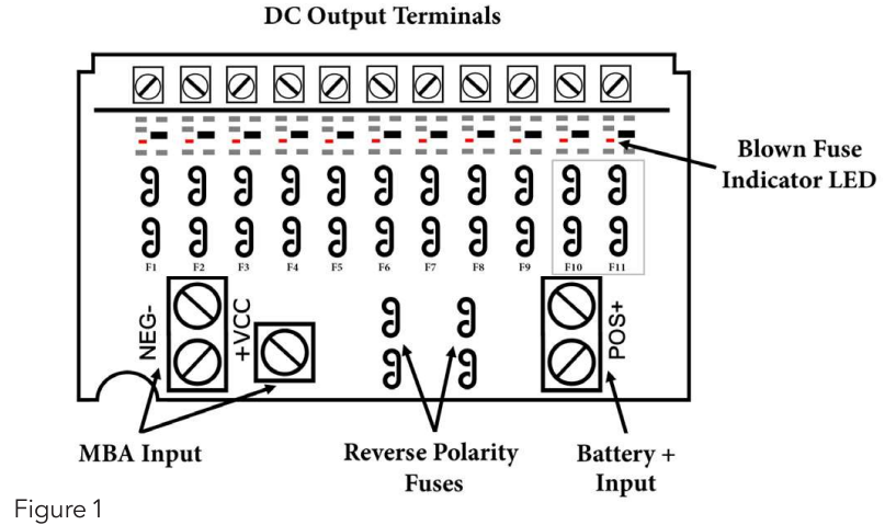
The WF-8900 Series Power Centers will charge the 12-volt House battery if installed. A battery DOES NOT have to be installed for WF-8900 Series Power Center converter operation. When a battery is installed, two reverse polarity fuses protect the converter circuitry. The fuses are located along the left-center edge of the DC fuse board below the VCC+ lug. Refer to Figure 1 below. This feature prevents permanent damage to the converter from a battery connected into the circuit backwards. In addition to protecting the converter section, the reverse polarity fuses are the main connection between the converter and the DC fuse board.
The fuse values and quantity vary depending on which WF-8900 Series Power Center you have. Refer to the table and drawing below.
- WF-8935 - 40A ( 1)
NOTE: Only one of the two Reverse Polarity terminals is used. - WF-8945 - 30A (2)
- WF-8955 - 40A (2)
- WF-8965 - 20A (4)
- WF-8975 - 20A (4)
Blown Fuse Indicators on DC Fuse Board
The DC Fuse Board has individual blown fuse indicators as standard equipment. Each of the 11 DC fuse circuits contain a Red LED to indicate a blown fuse. If one of the circuits draws more current than the rating of the fuse, the fuse will blow. When this occurs, the Red LED for that circuit will illuminate.
NOTE: The fuse board employs surface mount LEDs which are barely visible to the naked eye. Replace the blown fuse with a known good fuse of the same rating. NOTE: If the replacement fuse blows again, check that circuit for a short or overload condition.
Automatic Cooling Fan
The cooling fan in the WF-8900 Series Power Center is incremental and is controlled by the current drawn out of the converter to the applied load. The on-board microprocessor increases fan speed as the total load increases and decreases fan speed as the load
decreases. Unlike traditional temperature-controlled fans, the load-controlled fan provides better component cooling by avoiding temperature spikes which can lead to premature component failure.
Over-Temperature Protection
If the internal temperature of the converter exceeds a critical point, it will shut down. This protects the unit from excessive heat that may damage sensitive components. The unit will restart once the temperature inside has dropped.
Electronic Current Limiting
In the event that the output current exceeds the maximum rating for the WF-8900 Series Power Center converter, the output current will remain constant but the output voltage will begin to drop. If this occurs, the unit will recover once loads are reduced.
Short-Circuit Protection
Should a short circuit occur in the RV, the WF-8900 Series Power Center converter will drop the voltage output to zero volts. If the short-circuit condition is removed and no other fault conditions are detected, the converter will resume normal operation. However, short-circuit conditions are dangerous, and an RV will require inspection by a qualified service technician.
CIRCUIT PROTECTION
Center Fuses and Breakers
DC Fuses (12 Volts)
The DC fuse board has spaces for eleven DC circuits. This includes two 30 Amp circuits (positions F 10 and F 11) to be used for slide-outs or other higher current loads. These circuits have a maximum rating of 30 Amps. The remaining nine circuits have a maximum 20 Amp rating. The circuit fuses and the Reverse Battery Protection fuses should be replaced with ATC or ATO automotive-type fuses such as:
- Littelfuse type 257
- Bussmann type ATC
AC Circuit Breakers (120/240 Volts)
The AC Breaker side of the WF-8900 Series Power Center is located on upper the left side. The WF-8900 Series Power Center accepts standard residential breakers. A total of ten breakers can be installed: one 30 Amp Main breaker and up to a maximum of nine AC Branch circuits when using duplex breakers. A list of factory-tested and approved breakers follows. The breakers may be purchased at most big-box department stores and home centers.
UL-Listed Main Circuit Breakers, Rated for 120V, Maximum 30A
The following breakers have been factory tested and approved for use as 30 Amp Main breakers in the WF-8900 Series Power Center:
| Manufacturer | Model/Cat. No./Type |
|---|---|
| Cutler Hammer | Type BR and C |
| Thomas Betts | Type TB or TBBD |
| !TE/Siemens | Type QP or QT |
| Square D | Type HOM or HOMT |
| Murray | Type M P-T or MH-T |
| General Electric | Type THQL |
If you have the -GE model, you will need to use THQP GE Breakers.
When replacing any of the installed circuit breakers, the replacement should be of the same manufacturer, type designation, and equal interrupting rating, not to exceed 30 A. The "Short-Circuit-Current" rating for the breaker should be 10,000 Amps.
Breaker Filler Plates: Model #FP-01 or FP-0lB (Black)
OPERATIONAL FEATURES
Converter Operation Modes
Three-Stage Smart Charging
In order to maximize battery life, it is best to charge batteries slowly, keep them topped off with a trickle-charge when the RV is not being used. The 3-Stage "smart" charger continuously measures the battery voltage output and regulates the amount of charge using three modes of operation; Absorption, Bulk and Float modes.
All WFCO power converters are automatic three-stage switching power supplies. The converter senses which mode it needs to be in by checking the RV system voltage.
The converter normally provides a constant target output voltage of 13.6 VDC (nominal) to current power all reaches the its branch maximum, circuits. the However, output it voltage is current will drop limited, as and necessary if the to output hold the (load) converter's maximum output current level ( the Amperage rating) without exceeding it.
If the output current reaches its maximum (normally caused by a discharged battery), this will cause the converter to go into Bulk Mode, which means the target output voltage will change to 14.4 VDC and a timer will start. Although the converter is outputting 14.4 VDC, you will not be able to read that on a voltmeter due to the voltage-current relationship. From the paragraph above, as load current increases, output voltage decreases.
The actual output voltage will not rise until the load current is reduced, which happens naturally as the battery charges or if 12 VDC appliances are turned off. Bulk Mode will be maintained until the current draw drops to approximately five Amps, or until the timer reaches four hours (whichever happens first). Then the target output voltage is changed back to 13.6 VDC for Absorption Mode. Lights that are powered from the output may change brightness slightly at that time.

Note: For a detailed explanation of the charging modes, please refer to our publication "Theory of Operation': document # AD-TD-0001-0.
INSTALLATION
Mounting the Enclosure
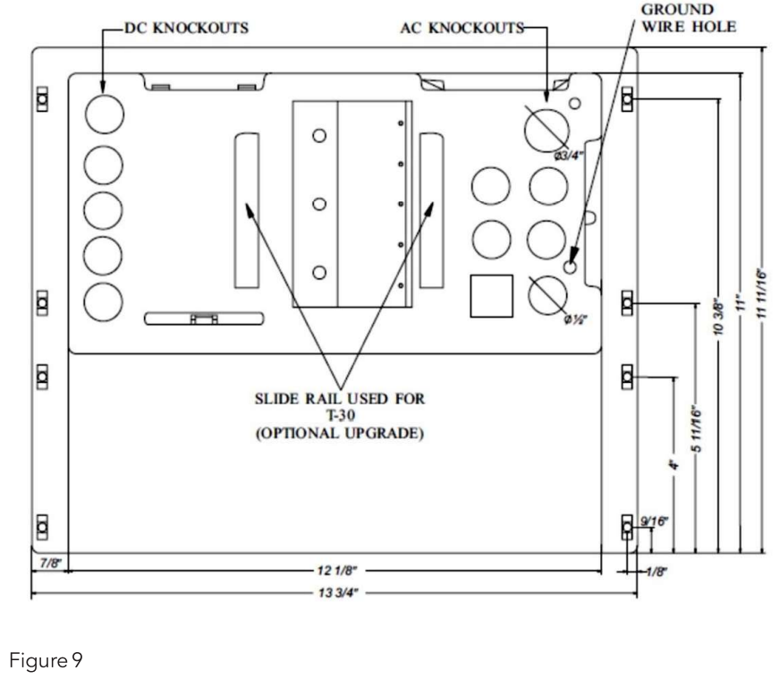
The WF-8900 Series enclosure should be mounted in an accessible area such as a wall or in the side of a cabinet. The front of the enclosure should not be obstructed to allow free air flow for the cooling fan. The enclosure will slide into a rough opening of 12 3/16" W x 10 7 /8" H. The enclosure depth is 7 1/4': After wiring is completed, the enclosure fastens to the wall or cabinet using 8 wood screws (not supplied).
WARNING
RISK OF ELECTRICAL SHOCK
Disconnect or isolate all power supplies before making electrical connections. More than one disconnection or isolation may be required to completely de-energize equipment. Contact with components carrying hazardous voltage can cause electric shock and may result in severe personal injury or death.
Wiring the AC Breakers
- Make sure no AC power is coming into the RV from either the Shore Power cord or an on-board generator. Determine the proper size breakers for the loads the WF-8900 Series Power Center will be powering.
- You can use either single or duplex breakers, or a combination of both. We recommend that all the breakers used be of the same brand.
When using duplex style circuit breakers, a total of 10 breakers can be mounted in the WF-8900 Series Power Center: 1 Main breaker and 9 Branch breakers.
Refer to the tables on pages 5 and 6 for a selection of approved breakers. The Main breaker should be 30 Amp and is to be installed in the top-most position.
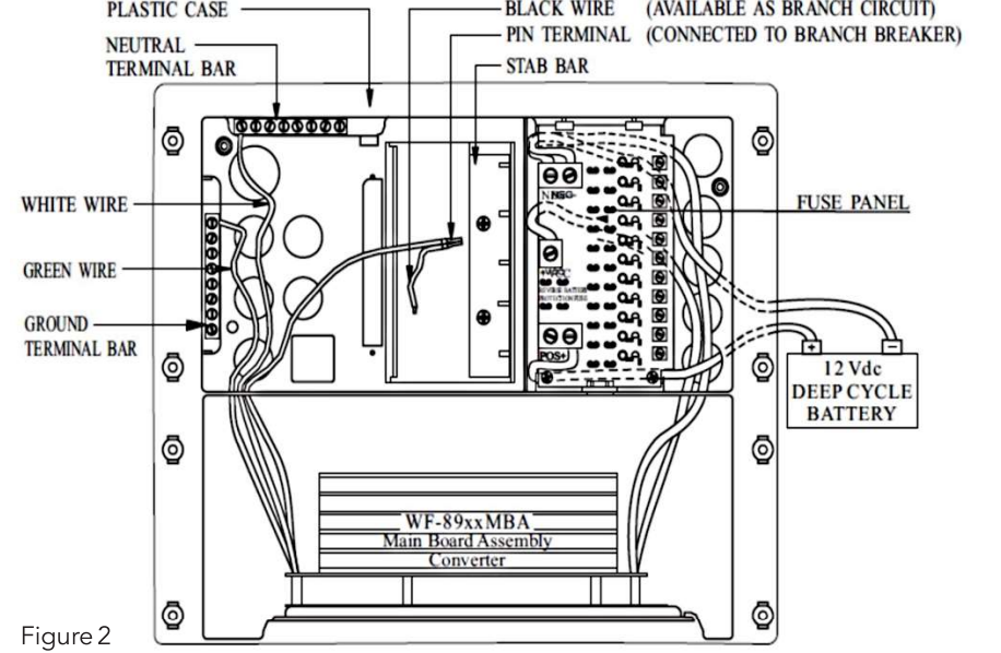
See the wiring diagram below.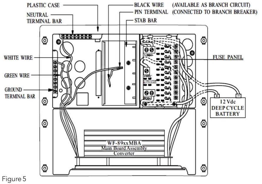
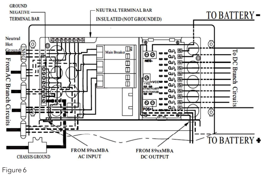
- A hold down clip is provided to keep the breaker securely in place.
- The 30 Amp power cord is routed through the large knockout in the wiring compartment and secured with a Romex clamp. The Black (Hot) wire is connected to the 30 Amp Main breaker as shown. The White (Neutral) wire is connected to the Neutral Terminal bar at the bottom of the wiring compartment. The Green (Ground) wire is connected to the Ground Terminal bar also located at the bottom of the compartment.
- Route the Romex leads for the Branch circuits through the Strain Reliefs in the back of the wiring compartment. In a similar fashion, connect the Black wire to the Branch breaker and the White and Green wires to the appropriate Terminal bar. Also, route an 8 AWG Green or bare Ground wire through the samll diameter hole located next to the Ground bar to the vehicle chassis.
- The Black power wire for the converter has a pigtail connection. The metal pin is inserted in the Branch breaker designated for converter power. The end with the wire nut can be used to power another circuit if necessary. If not used, leave the wire nut installed and push the wire to the side. Make sure all terminals are torqued to the specifications listed on the back of the door assembly.
Wiring the DC Fuse Board
Make sure the house battery is disconnected before beginning the DC wiring. Determine what DC loads are to be connected to the fuse board and what position they will occupy. Circuits FlO and Fll can be used for slide-outs or other higher current loads and can have a maximum 30 Amp ATO or ATC fuse installed. The remaining circuits are general purpose and can have up to 20 Amp ATO or ATC fuses installed. Make sure the fuses are seated properly.
All models have output screw terminal connections. Strip approximately 1 / 4" of insulation from the load's wire and insert into the screw terminal. Tighten the terminal to the torque specified on the back of the enclosure.
Connect the heavy wire (Red) coming from the battery to the POS+ lug located directly below the Reverse Polarity fuses. Make sure this lug is torque properly.
As a last step, install a separate bus bar in a location behind the converter. This bus bar can be purchased from a local home center or hardware store. For the WF-8935/8945/8955, run an 8 AWG wire from the NEG- lug on the top left of the DC fuse board to this bus bar.
For the WF-8965/8975, run a 6 AWG wire. Connect the battery negative wire to this bus bar along with all the negative DC load wires. Also, run a wire from the bus bar to chassis ground.

Setup Guide
To set up the wfco Power Center Fuse & Breaker WF-8975, follow these steps:
- Choose a suitable location for the power center, ensuring it is accessible and protected from the elements.
- Mount the unit using the provided hardware, following the manufacturer's instructions for secure installation.
- Connect the AC and DC power inputs according to the wiring diagram provided in the manual.
- Configure each circuit breaker and fuse according to your specific electrical needs.
- Test the system to ensure all circuits are functioning correctly.
WARNING
RISK OF ELECTRICAL SHOCK
Disconnect or isolate all power supplies before making electrical connections. More than one disconnection or isolation may be required to completely de-energize equipment. Contact with components carrying hazardous voltage can cause electric shock and may result in severe personal injury or death.
NOTICE
All wiring must conform to local, national, and regional regulations. Use copper conductors only for all wire connections. Do not exceed the electrical ratings for the WF-8900 Series Power Center as this may cause equipment failure and/or electrical shock which may result in severe personal injury or death.
CAUTION
EQUIPMENT SERVICING
This product should be installed by an experienced certified technician. CAUTION and care must be taken when servicing this equipment. To prevent severe shock or electrocution, consult your servicing dealer.
WARNING
SPARK HAZZARD
This unit employs components that can produce arcs or sparks. To prevent fire or explosion, do not install in compartments containing batteries or flammable materials (LP gas). This product is NOT ignition protected.
CAUTION
DO NOT OBSTRUCT VENTILATION OPENINGS
To prevent fire, DO NOT cover or obstruct enclosure ventilation openings. DO NOT mount the WF-8935, WF-8945 or WF-8955 units in a zero-clearance compartment as overheating may result. These units require a 2 cubic foot (min) vented area behind the unit for cool air exchange.
WARNING
BATTERY SYSTEM
Use converter only on appropriate battery systems. Other usage may cause personal injury and damage. Consult all battery manufacturer's recommendations for additional safety information before use.
Troubleshooting
Refer to the Troubleshooting Guide for the WF-8900 Series Power Center (Figure 4) below.
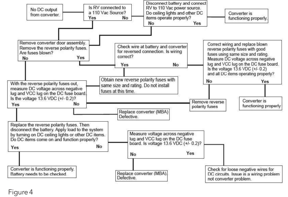
Converter Output Voltage
- Before checking the WF-8900 Series Power Center output voltage, disconnect the battery cables at the battery.
- Make sure the converter is plugged into an AC source (105-130 VAC). Check the converter output voltage at the battery with a voltmeter.
- Place the meter probes on the disconnected battery cables; place the Positive (red) meter probe on the + Positive red battery wire and place the Negative (black) meter probe on the - Negative black wire on the battery cable.
- Be sure you have good connections at the cables. If the voltage reads 13.6 VDC ( +/- 0.2) with no load, the converter is functioning properly
- If the converter output voltage at the battery reads 0.0 VDC, or if the battery is not charging, check for an open inline fuse in the battery wire circuit. One may have been installed by the RV manufacturer. Also check for loose wiring connections.
Reverse Polarity Fuses
If there is no DC output coming from the WF-8900 Series Power Center converter section,
- First check the reverse polarity fuses on the fuse board.
- Then, visually inspect the fuses for any breaks in the fuse element.
- If no breaks are found, use a continuity tester to check for continuity.
- If the reverse polarity fuses are blown, it means the RV battery was accidentally connected in reverse, either at the battery or at the converter.
- Investigate the connections and reconnect the cables properly.
- Replace the fuse with the same type and amperage rating as the original.
IMPORTANT: These fuses protect the converter from damage in the event that the RV battery is accidentally connected in reverse. A reversed battery connection, even if for only a second, will cause these fuses to blow.
If the above checks have been made but the converter output still reads 0.0 VDC, the converter is not functioning properly. Before placing the call, please have available the WF-8900 Series Power Center model number from the front panel label and the 14-digit serial number from the bar code tag located on the MBA mounting plate.
Troubleshooting Guide for the WF- 8900 Series Power Center
Should it be determined that the converter section of the WF-8900 Series Power Center needs to be replaced, removal of the Main Board Assembly is a simple process.
Replacing the Converter Section (MBA)
Make sure no AC power is coming into the RV from either the Shore Power cord or an on-board generator. Remove and set aside the Reverse Polarity Fuses to disconnect the converter section from the rest of the RV DC power.
Perform the following steps:
- Remove the door assembly by loosening the two screws located in the upper left and right corners. The screws are captive and will not fall out. Pull forward and outward on the door assembly to clear the case.
- In the upper left portion of the fuse board, loosen the NEG- lug (White wire) and the VCC+ lug (Red wire). Do not back the lug screws all the way out.
- Locate the tab at the bottom of the fuse board holding the board in place. Gently depress the tab allowing the fuse board to be pulled forward.
- With the fuse board pulled slightly away from its mounting, pull the Red and White wires out of the lugs.
- In the AC section of the enclosure, locate the Black wire coming up from the converter in the lower section. As an extra precaution, MAKE SURE THE CONVERTER BREAKER IS IN THE OFF POSITION. Remove the wire from the breaker.
NOTE: this wire has a metal pin terminal on the end inserted into the breaker. Remove and position out of the way any wire connected to the pigtail. - Locate and remove the converter's Green Ground wire attached to the AC Ground bar on the left side of the compartment. In a similar fashion, locate and remove the converter's White Neutral wire attached to the AC Neutral bar at the top of the compartment.
- In the converter compartment, remove the two screws at the front of the MBA holding it in place. Slide the MBA forward routing the wires through the slots in the case until the MBA clears the enclosure.
If the MBA is being returned under a warranty claim, follow the packaging instructions in your warranty claim packet.
When installing a replacement MBA, reverse the order of steps 1-7. Make sure all wiring connections are torqued to the proper values found in the toque chart located on the back of the door assembly.
Power Center Fuse & Breaker WF-8975 Pros & Cons
Pros
- Combines fuse and circuit breaker functions in one unit
- Provides comprehensive electrical protection with GFCI and OCP
- Durable and rust-resistant construction
- Easily mountable and accessible design
- User-friendly layout for easy monitoring and management
Cons
- Slightly higher cost compared to separate fuse boxes and circuit breakers
- Requires careful installation to ensure proper functioning
- May require additional wiring or adapters depending on the vehicle's electrical system
Customer Reviews
Customers have generally praised the wfco Power Center Fuse & Breaker WF-8975 for its reliability and ease of use. Many have noted that it simplifies electrical management in their RVs, providing peace of mind with its robust protection features. However, some users have mentioned that the initial setup can be complex and time-consuming.
Faqs
What is the maximum AC power rating of the wfco Power?
How many DC circuit breakers does the WF-8975 include?
What type of protection does the GFCI in the WF-8975 provide?
Is the wfco Power Center Fuse & Breaker WF-8975 easy to install?
Can I use the wfco Fuse & Breaker in both RVs and motorhomes?
What should I do if a circuit breaker keeps tripping?
How do I reset the GFCI on the wfco Power Center Fuse & Breaker WF-8975?
Is the Breaker durable and long-lasting?
Can I purchase additional fuses and circuit breakers for the WF-8975?
What is included in the packaging of the wfco Power Center Fuse & Breaker?
Leave a Comment
