Apluslift 2-Post Floor Plate Car Lift HW-10KBP Guide
Content
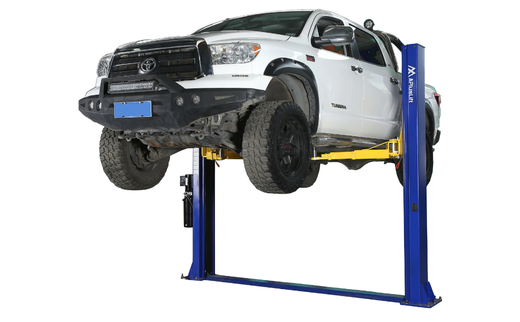
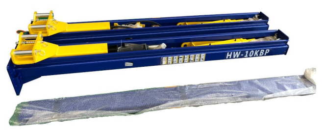
Introduction of apluslift 2-Post Floor Plate Car Lift HW-10KBP
The apluslift 2-Post Floor Plate Car Lift HW-10KBP is a heavy-duty car lift designed for professional use in auto repair shops and garages. With a lifting capacity of 10,000 lbs, this lift is suitable for a wide range of vehicles, including sedans, SUVs, and light trucks. The estimated price of the apluslift 2-Post Floor Plate Car Lift HW-10KBP is around $3,000 to $3,500, and it was launched in 2021.
Specification and Features
| Feature | Description |
|---|---|
| Heavy duty design | Yes |
| Column steel thickness | 13/64" |
| Carriage steel thickness | 15/64" |
| Carriage yoke thickness | 9/16" |
| Arm steel thickness | 15/64" |
| Base plate steel thickness | 5/8" |
| Driving mode | Dual hydraulic cylinders, chain drive |
| Voltage | 220V 60Hz |
| Lifting capacity | 10,000 LB |
| Combo arm assembly | Symmetrical and asymmetrical |
| Safety mechanism | Double point safety lock release, etc. |
| Control system | Lifting by "UP" button, manual lowering, etc. |
| Overall height | 113 5/8" |
| Overall width | 134 5/16" |
| Maximum lift height with adapters | 81" |
| Minimum height of arm top | 4" |
| Time to full rise | 50 sec |
| Motor | 3 HP |
| Shipping weight | 1,350 LB |
Parts List for APlusLift HW-10KBP 2-Post Car Lift
| Item | Description | Quantity |
|---|---|---|
| 1 | Floor plate (insert two ends of the floor plates to columns) | 1 |
| 2 | M10x35 socket head cap screws for floor plate (pre-installed) | 2 |
| 3 | Columns (pre-assembled with cylinders) | 2 |
| 4 | Lift arms | 4 |
| 5 | Arm pins (connect arms to carriage) | 4 |
| 6 | Racks (toe guard) | 2 |
| 7 | M10x16 Socket bolts (mount the racks to arms, pre-installed) | 4 |
| 8 | Tool box (put on the racks) | 2 |
| 9 | Power unit (220V single phase with manual release handle) | 1 |
| 10 | M8x25 bolts, washers & nuts (mount power unit onto the column) | 4 |
| ... | ... | ... |
Description
The apluslift 2-Post Floor Plate Car Lift HW-10KBP features a symmetric design with two posts that are 90 inches tall and 5 inches by 5 inches in diameter. The lift is equipped with a single-piece 1.25-inch diameter steel aircraft cable and a heavy-duty hydraulic cylinder that provides smooth and reliable operation. The lift also features a dual-point lock release system for added safety and convenience. The floor plates measure 26 inches by 60 inches and are designed to provide maximum stability and support.
Part List
| Item | Description | Quantity |
|---|---|---|
| 1 | Floor plate (insert two ends of the floor plates to columns) | 1 |
| 2 | M10x35 socket head cap screws for floor plate (pre-installed) | 2 |
| 3 | Columns (pre-assembled with cylinders) | 2 |
| 4 | Lift arms | 4 |
| 5 | Arm pins (connect arms to carriage) | 4 |
| 6 | Racks (toe guard) | 2 |
| 7 | M10x16 Socket bolts (mount the racks to arms, pre-installed) | 4 |
| 8 | Tool box (put on the racks) | 2 |
| 9 | Power unit (220V single phase with manual release handle) | 1 |
| 10 | M8x25 bolts, washers & nuts (mount power unit onto the column) | 4 |
| 11 | Hydraulic long hose 9 1/2 feet (connect fittings on two cylinders) | 1 |
| 12 | Hydraulic short hose 3 1/2 feet (connect cylinder fitting to power unit) | 1 |
| 13 | Extended fitting 4 1/4 inches (connect short hose to cylinder) | 1 |
| 14 | Short fitting to cylinders (pre-installed) M16x1.5 male to M14x1.5 male | 2 |
| 15 | Truck adapters | 4 |
| 16 | Screw-in pads | 4 |
| 17 | Wire rope equalizer cables with M18x2.5 thread-on nuts & washers | 2 |
| 18 | Anchor bolts (3/4"x6") | 10 |
| 19 | Door guards protection rubber | 2 |
| 20 | M6x16 socket bolts (mount door guards to carriages) | 4 |
Setup of apluslift 2-Post Floor Plate Car Lift HW-10KBP
To operate the 2-Post Floor Plate Car Lift HW-, follow these steps
- Before using the lift, make sure to read and understand the user manual.
- Inspect the lift for any damages or defects before each use.
- Position the lift on a level and stable surface.
- Drive the vehicle onto the lift plates, centering it on the lift.
- Raise the lift using the manual pump or electric motor until the lift locks into place.
- Perform the necessary maintenance or repairs on the vehicle.
- Lower the lift slowly and evenly until the vehicle is fully supported by its own wheels.
- Remove the vehicle from the lift and repeat the process as necessary.
Important Information
READ THIS BEFORE INSTALLING THE LIFT! Improper installation can cause injury or damage
- Read this installation and operation manual in its entirety before attempting to install the lift. Manufacturer or distributor assumes no responsibility for loss or damage of any kind, expressed or implied, resulting from improper installation or use of this lift. Always use professional installation companies.
- All persons using the equipment must be responsible, qualified, and carefully follow the operation and safety guidelines contained in this manual.
- A level floor is required for proper lift installation and operation.
- DO NOT install this lift on any asphalt surface. Recommend on concrete surface a minimum of 6” thick and 3,500 psi tensile strength with steel or fiber mesh reinforcement. If you always lift vehicles below 9,000LB, 4” thick concrete will be fine.
- DO NOT install this lift over concrete expansion joints or cracks. (Check with your building architect)
- DO NOT install this lift on an upper floor without written authorization from your building architect. Should only be installed on a ground floor without a basement.
- DO NOT attempt to lift only part of a vehicle. This lift is intended to raise the entire body of a vehicle only. This will bend the arms and void the warranty.
- NEVER lift any persons or vehicles containing persons. This lift is designed to lift empty vehicles only.
Preparation
- Concrete rotary hammer drill with 3/4" drill bit
- Rubber hammer
- Chalk line
- Sockets and open wrench set
- Ratchet driver
- Vise grips
- Tape measure
- Screwdrivers
- Torque wrench
- Two 10' to 12' step ladders
- 4' level
- 12" crescent wrench
- AW32 non-foaming hydraulic fluid (4 gallons)
Installation Requirements
- Use proper lifting techniques when lifting individual pieces. Use plenty of help when moving lift pieces. Please wear work gloves to protect your hands.
- The lift should be installed on a leveled floor with a slope of less than 3 degrees.
- Do not install this lift on asphalt, wood, or any other surface other than described.
- Do not install this lift outdoors unless special consideration has been made to protect the power unit from inclement weather conditions.
- Do not install lift in a basement or on any level other than ground level (such as the second floor) without written authorization from your building engineer or architect.
- Concrete surface shall have a minimum of 6" thick and 3,500 psi tensile strength with steel or fiber mesh reinforcement (If you always lift vehicles below 9,000LB, 4” thick concrete will be fine). Minimum size of a slab: 216"L x 100"W x 6"H 3500 psi.
- Alternatively, columns can be installed on two concrete footings. 2 ft x 2 ft with 30" deep (or 3 ft x 3 ft with 12" deep) and 3500 psi tensile strength with steel or fiber mesh reinforcement.
- Maintain a 6" minimum distance from a slab edge. Do not install this lift over expansion joints or cracks. Check with your qualified engineer or architect.
- Leave spaces on all 4 sides when placing the lift. Recommended at least 2’ distances on all 4 sides when a vehicle is loaded.
- Improper installation can cause damage or injury. Manufacturer will assume no liability for loss or damage of any kind, expressed or implied, resulting from improper installation or use of this product.
- The lift is for lifting vehicles only. It is not designed to lift a person or an equipment with a person.
- Read this installation manual in its entirely before attempting to install this lift.
- Use of this lift should follow the operation and safety guidelines set forth in this manual.
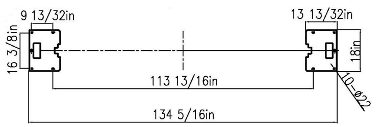
Anchoring Tips
Check the following diagram for the footprint of columns with anchor bolts positions.
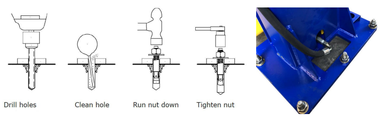
- Use a concrete rotary hammer drill with 3/4” drill bit. Do not use excessively worn or incorrectly sharpened drill bits.
- Keep the drill in a perpendicular position when drilling. Let the drill do the work. Do not apply excessive pressure.
- Lift the drill up occasionally and clean residue in the hole.
- Drill the holes 1" deeper than the length of the anchor bolts. Drill through the concrete is recommended (when you move the lift to a new location, you may hammer down the anchor bolts instead of cutting them off).
- For better holding, power blow dust from the hole.
- Place a flat washer and hex nut over threaded end of anchor, leaving approximately 1/2" of thread exposed. Carefully tap the anchor. Do not damage threads. Tap the anchor into the concrete until the nut and flat washer are against the base plate. Do not use an impact wrench to tighten. Tighten the nut two or three turns after the concrete is cured (28 day minimum cure). If the concrete is very hard, tighten only one or two turns.
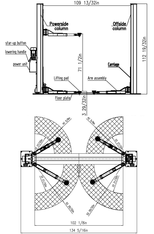
Asymmetrical Arm Diagram
Installation Instructions
Preparation
- Please carefully remove all the parts from the package.
- Remove any loose cables, hoses, part boxes, hydraulic power unit, etc. if they are inside the columns or banded to the columns.
- Remove the power unit box and four swing arms
- Remove the bolts holding the two columns together. Remove top and bottom columns out of the skid and discard the steel rack.
- Compare the parts with the part list (at the end of the manual) and contact us if there are any parts missing.
- Please read the installation requirements and anchoring tips in previous pages for concrete requirement, layout, and drill holes for anchor bolts. The area where the lift will be installed should be free of overhead obstructions such as heater, building support, or electrical lines.
- Once a location is determined, use a carpenter’s chalk line to layout a grid for the column locations
- After the post locations are marked, use a chalk to make an outline of the posts on the floor at each location using the post base plates as a template.
- Double check all dimensions and make sure that the layout is perfectly square.
- Determine the side that the power unit column will be located. The power unit column can be located on either side. Keep in mind this is the column where your main electrical power supply will be connected. It is recommended to locate the power side with the passenger side of the vehicle when loaded on the lift in order to save steps during operation.
- Double check measurements and make sure that the base plate of each column is square and aligned with the chalk line.
- Stand up the power unit column (the one with the power unit bracket welded on) and position it inside the chalked lines. The column should face straight toward the other column.
- Stand up the other column opposite to the main power unit column inside the chalk lines.
- Make sure the height difference of two columns is within 1 inch, otherwise the carriages will not be locked at the same (height) locking positions.
- Place the floor plate between two columns and align the mounting holes with the inside base plate holes. This will make sure proper spacing between columns.
- Please note the floor plate is not bolted to columns or ground.
- Using a tape to measure from back corner to back corner of the base plate to ensure columns are square to each other. Adjust columns as needed to obtain the best fit.
- Drill holes with 3/4 inch drill bit into concrete following Anchoring Tips on page 4.
- Assemble washers and nuts on the anchors and then tap into each hole with a rubber hammer until washers rest against the base plate. Do not tighten anchor bolts at this time.
- Use a level to check the level of each base plate. Place horseshoe shims under the base plate (near anchor bolts) as needed. When base plates are leveled, columns may tilt outward slightly. When a vehicle is loaded, the columns will flex inward to correct it.
- Tighten 10 anchor bolts and recheck for level. Hammer the anchor bolts all the way down. Tighten anchor bolts using a torque wrench to 125 ft. / lb. DO NOT use an impact wrench when tightening the anchor bolts!
- Now remove the steel floor plate cover.
- Manually lift the carriage on each column about waist high. Let carriages down and allow them to set on safety latch stops. Make sure they are at the same height. Double check the latches before working under the carriages.
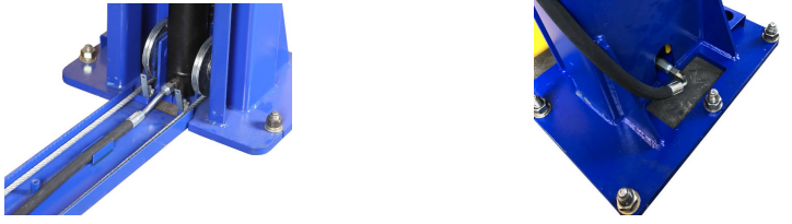
Installing Equalizing Cables
- Take the equalizer cables. Using vise grips and a socket, tighten the cable nut half way down the threads.
- Stand in front of each carriage and find two holes on the top of the carriage.
- Take the threaded end (the end without a nut) and run it through the right side of the carriage. See the figures below for cable routing. Do not tighten cables at this time. Just start them on the treads.


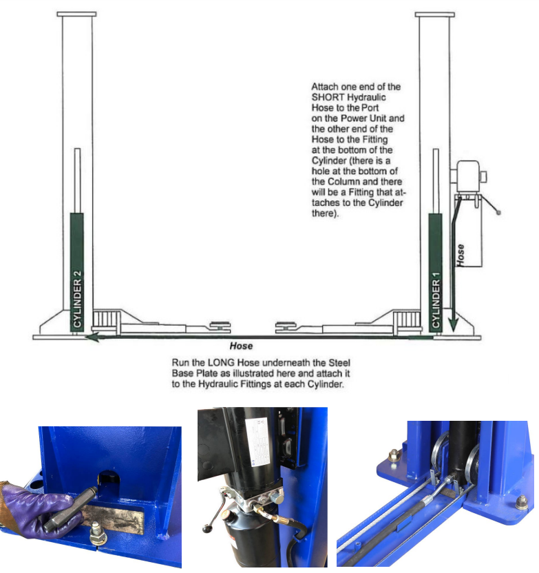
Installing Power Unit and Routing Hydraulic Hoses
- Mount the power unit onto the main side column with four hex bolts.
- Connect 4 inches fitting to the cylinder in main side column. Connect short hydraulic hose to the fitting.
- Connect short hydraulic hose to the power unit.
- Connect long hydraulic hose between the cylinders and let it lay inside the floor plate.
- See figures below for hose layout and routing to the power unit.
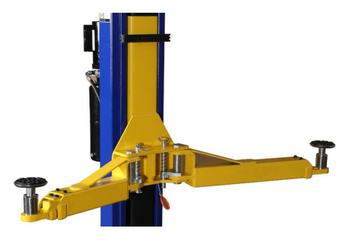
Installing Swing Arms
- Locate the 4 swing arms and swing arm pins. Take one of the arms and insert it over the hole in the carriage torsion tube. Line up the holes and insert the pin. Repeat for the three other arms.
- We recommend putting 3-stage arms on the front and 2-stage arms on the back when the car lift is used asymmetrically. Details
Electrical Connection to Power Unit
- Warning: The wiring must comply with local code. Please find a certified electrician to connect the power unit to a 220V power outlet. Please protect each circuit with a time delay fuse or circuit breaker.
- The car lift uses a 220V single phase power unit. The running amperage is 10A. Recommend a 30A breaker and a 10-gauge wire.
- For 220V single split phase with two hot wires
- wire brown to hot 1
- wire blue to hot 2
- wire yellow/green to ground
- For 220V power with one hot and one neutral wires
- wire brown to hot
- wire blue to neutral
- wire yellow/green to ground
- See the figure on the right for reference.

Hydraulic Fluid and Adjustment
Cable Adjustment
- Place a pair of small or medium vise grips around the shoulder of the long threaded adjusting bolt on the cable to make any adjustments.
- Use a deep socket to adjust the slack out of the cable. Adjust tension to cables equality.
- DO NOT over tighten. Note: If one of the cables is tighter than the other, the carriage will go up uneven. These should be tightened like a banjo string or fan belt.
Hydraulic Fluid
- Remove vent plug from the top of the reservoir. You are going to fill the tank with fluid. AW 32 or 46 hydraulic oil is recommended. We do not recommend the transmission fluid as it is too thin. The unit will hold approximately 2.64 gallons (10 liters) of fluid.
- If the arms go all the way to the top, hydraulic oil will flow to two cylinders. If the arms go all the way to the bottom, hydraulic oil will flow back to the pump.
Carriage Adjustment and Synchronization
- One of the most important things to remember is not to tighten down one side more than the other. The key is to tighten one side a half dozen turns then the opposite side a half dozen turns. After getting both cables equally tight (YOU SHOULD BE ABLE TO MOVE THE CABLES ABOUT AN INCH BACK AND FORTH WITH SLIGHT PRESSURE LIKE A FAN BELT OR A BANJO STRING) raise the lift all the way up by pressing the UP Button on the power unit. Do not bottom the lift out at the top by holding down on the switch.
- Raise the lift off the latch (lock) by pushing the power button, this will enable you to pull each release cable ring located at the bottom of both carriages. Pull down on the lowering valve handle (lever) on the power unit and lower the lift all the way to the floor. Raise the lift again and listen for the clicking of the safety locks in each column. Determine which side is slower and tighten the adjusting bolt on the opposite side carriage. Remember to only tighten a few turns at a time until the both locks click at the same time when raising the lift. Cycle the lift up and down. Repeat the adjustment until the carriages are within a 1/4” of each other or the clicks are almost at the same time with each side. When cables are adjusted properly they should be fairly tight.
Safety Latch Adjustment
- If the safety latch in either column does not operate, adjust with the procedure below.
- DO NOT set the lift on the safety latch for this adjustment. Allow the hydraulic system to hold the lift during the adjustment. DO NOT put a vehicle on the lift
- Remove the plastic cover. Raise the lift until you can see the latch through the access hole on the column.
- Locate the latch
- If the latch is not working during descent, loosen the adjustment bolt one full turn. Test the latch and follow this procedure until the latch operates.
- If the latch is not working during ascent, tighten the adjustment bolt one full turn. Test the latch and follow this procedure until the latch operates.
Final Setup
Mount The Floor Plate Cover
Mount the floor plate cover tight with socket head cap screws.
Check Assembly
- Check all bolts and nuts to make sure they are tight. Do not use an impact gun on concrete Anchors.
- Check all fittings or leaks. If necessary, make sure the arm lock restraints are engaging properly and smoothly. If not, tap the main lock forward or backward as needed with a rubber mallet to insure proper engagement on all 4 gears with the arm restraint locks.
- Cycle lift up and down to insure carriages are synchronized.
Screw-In Pads and Truck Adapters
- Before lifting a vehicle, please adjust the height of screw-in pads to fit.
- Use truck adapters if needed. Please remove the snap rings from the screw-in pads before using the pads with truck adapters.
- Never exceed 9" of pad height.
Test & Adjust Lift
- With the power properly hooked up and hydraulic oil in the pump reservoir, push the push button on the side of the Motor to raise the carriages off the locks. Release the push button and then pull the lock release cable under each carriage to release the locks. Run the lift all the way up and down two more times to bleed all the air from the system.
- While running the lift, listen to safeties clicking. Each side should click simultaneously or with-in a 1/2 second of each other. If they are not clicking together, then adjust the cables to compensate by tightening the side opposite the one that is clicking last at the cable bolt at the top of the carriage on the same side.
- Remember not to over tighten cables – they should be firm, much like a banjo string or a fan belt in a car.
Bleed Air from Cylinders
- Place a vehicle on the lift and raise until swivel pads are in contact with the frame of the vehicle. Raise the vehicle about 3 feet and then lower the vehicle until the tires touch the floor. Keep raising and lowering the vehicle a few times and increase the height each time until the vehicle completely reaches to the top. This procedure pumps all the air from the system.
- Lifting speed will be faster (be normal speed) after air is bled out.
Operation
Only authorized personnel can operate the lift. Please read operating and safety procedures carefully before operating the lift.
- Maintain and inspect lift in accordance with the owner’s manual. Never exceed the capacity.
- Do not operate a lift that is damaged or in need of repair.
- Allow only authorized persons in the lift area.
- Keep the lift area clear when raising or lowering the lift. NO RIDERS.
- Keep hands and feet away from pinch points at all times.
- Never override the lift's operating and safety controls
- If a vehicle is suspected of falling, clear the area immediately.
- Do not rock the vehicle while positioned on the lift.
- Always use safety jack stands when installing or removing parts from a vehicle.
Vehicle Loading
- Position vehicle at the center of gravity between the pads. Make sure the vehicle is neither front or rear heavy.
- Place pads at vehicle manufacturer’s recommended pick up points. Make sure the pads are in proper and safe positions to support the vehicle.
- Use caution before lifting pickup trucks, SUVs and other framed vehicles.
- Use truck adapters as needed. Never exceed 9" of pad height.
Raising Lift
- Push up switch to raise lift (make sure arm restraints engage or stop and slightly move arm to allow gear to mesh) until tires clear the floor.
- Stop and check for secure contact on adapters and vehicle weight distribution. If secure, raise to your desired height.
- ALWAYS lower the lift into the nearest lock position by pressing the lower lever to relieve the hydraulic pressure and then let the latch set in a lock position.
- Never work under a lift when the lift is not in a locked position.
Lowering Lift
- Clear all obstacles under the lift to ensure that only the operator is near the lift area.
- Stay clear of lift and raise the lift off the safety locks by 2”.
- Pull the safety latch which releases the cable ring one by one on each carriage and press the lower lever to lower the lift.
- Unload the lift by first completely lowering the lift and then swinging the arms to drive through position before moving the vehicle.
Maintenance
The following periodic maintenance schedule is the minimum requirements at the minimum intervals. Periodic maintenance is to be performed on a daily, weekly, and yearly basis.
WARNING!! OSHA AND ANSI REQUIRE USERS TO INSPECT LIFTING EQUIPMENT AT THE START OF EVERY SHIFT. THESE AND OTHER PERIODIC INSPECTIONS ARE THE USER'S RESPONSIBILITY.
FAILURE TO HEED THIS WARNING CAN RESULT IN PROPERTY DAMAGE, SERIOUS INJURY, OR DEATH. IF YOU HEAR A NOISE NOT ASSOCIATED WITH NORMAL LIFT OPERATION OR IF THERE ARE ANY INDICATIONS OF IMPENDING LIFT FAILURE, CEASE OPERATION IMMEDIATELY! INSPECT, CORRECT, AND/OR REPLACE PARTS AS NEEDED.
Daily Pre-Operation Check (8-Hours)
- Check the safety lock audibly and visually while in operation
- Check the safety latches for free movement and full engagement with the rack.
- Check the hydraulic connections, and hoses for leakage.
- Check the chain connection: cracks, bent, and loose links.
- Check the cable connection: cracks, bent, and looseness.
- Check for frayed cables in both raised and lowered positions.
- Check snap rings at all rollers and sheaves.
- Check the bolts, nuts, and screws and tighten if needed.
- Check the wiring & switches for damage.
- Keep the base plate free of dirt, grease or any other corrosive substances.
- Check the floor for stress cracks near anchor bolts.
- Check the swing arm restraints.
Weekly Maintenance (every 40-Hours)
- Check the anchor bolts torque to 125 ft/lbs for the 3/4 inch anchor bolts. Do not use an impact wrench to tighten the anchor bolts.
- Check the floor for stress cracks near anchor bolts.
- Check the hydraulic oil level.
- Check and tighten the bolts, nuts, and screws.
- Check the cylinder pulley assembly for free movement or excessive wear on the cylinder yoke or pulley pin.
- Check the cable pulley for free movement and excessive wear.
Yearly Maintenance
- Lubricate the chains
- Grease the rub blocks and column surface contacting the rub blocks
- Change the hydraulic fluid. It is an important maintenance procedure to keep the hydraulic fluid clean. No hard fast rules though. Operating temperature, type of service, contamination levels, filtration, and chemical composition of the fluid should be considered. If operating in a dusty environment a shorter interval may be required.
- Special Maintenance Tasks (performed by a trained maintenance expert only)
- Replace the hydraulic hoses.
- Replace the chains and rollers.
- Replace the cables and sheaves.
- Replace or rebuild the cylinders
- Replace or rebuild the pumps/motors.
- Checking of hydraulic cylinder rod and rod end (threads) for deformation or damage.
CAUTION! Relocating or changing components may cause problems. Each component in the system must be compatible. An undersized or restricted line may cause a drop in pressure. All valve, pump, and hose connections should be sealed and/or capped prior to use. Air hoses can be used to clean fittings and other components. However, the air supply must be filtered and dry to prevent contamination. Most important is cleanliness. Contamination is the most frequent cause of malfunction or failure of hydraulic equipment.
Troubleshooting
If you encounter any issues with the 2-Post Floor Plate Car Lift HW-10KBP, check for the following common problems and solutions
- The lift is not lifting: Check the hydraulic system for leaks and the electrical connections for proper power.
- The lift is not lowering: Make sure the lock release is engaged and the hydraulic system has sufficient oil.
- The lift is swaying or unstable: Check the floor plates for debris or unevenness and adjust the lift accordingly.
- The lift is making unusual noises: Check the lift for loose parts and tighten as necessary.
Warranty
Songa Enterprises Inc (DBA APlusLift) offers a limited two-year warranty to the original purchaser of lifts and wheel service equipment in the United States and Canada. APlusLift will replace, without charge, any part found defective in materials or workmanship under normal use, for a period of two years after purchase. APlusLift offers free shipping of parts to the lower 48 states of the US. The purchaser is responsible for shipping charges to other states, countries, or territories. This warranty does not apply to equipment that has been improperly installed or altered or that has not been operated or maintained according to specifications.
Pros & Cons of 2-Post Floor Plate Car Lift
Pros
- Heavy-duty lifting capacity of 10,000 lbs
- Symmetric design for versatile use
- Dual-point lock release system for added safety
- Single-piece steel aircraft cable for durability
- Floor plates for added stability
Cons
- Expensive compared to other car lift models
- Requires a level and stable surface for proper use
- May require professional installation
- Large footprint may not be suitable for small garages
Customer Reviews of apluslift 2-Post Floor Plate Car Lift HW-10KBP
Customers have praised the 2-Post Floor Plate Car Lift for its heavy-duty lifting capacity and durable construction. Some have noted that the lift requires a professional installation, and others have reported issues with the hydraulic system. However, overall, the lift has received positive reviews for its reliability and safety features.
Most Common Complaints
The most common complaints about the apluslift 2-Post Floor Plate Car Lift HW-10KBP include issues with the hydraulic system and the need for professional installation. Some customers have also reported difficulty in finding replacement parts for the lift.
Faqs
In what ways does the APlusLift HW-10KBP improve the safety of the garage?
What are the requirements for using the APlusLift 2-Post Car Lift HW-10KBP in a business setting?
Is it possible for me to install the APlusLift HW-10KBP Car Lift on my own?
What categories of automobiles are capable of being lifted by the APlusLift HW-10KBP?
When it comes to the installation of the APlusLift HW-10KBP Car Lift, how much space is required?
Is there any specific flooring that must be installed in order to accommodate the APlusLift HW-10KBP installation?
I have an APlusLift HW-10KBP Car Lift; what is the best way to maintain it?
Can you tell me the maximum speed at which the APlusLift HW-10KBP Car Lift can lift?
In what ways does the APlusLift HW-10KBP guarantee the stability of the vehicle while it is being lifted?
Does the APlusLift HW-10KBP come with a guarantee with the purchase?
Leave a Comment