
How to Use & Install: Diy Kit Bluetooth Amplifier Audio Speaker User Guide
Content
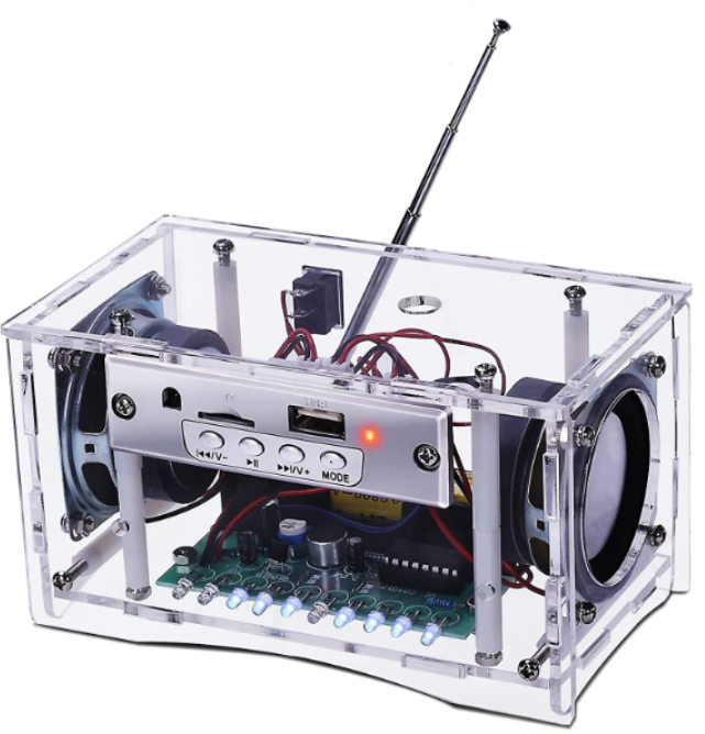
FM Bluetooth Amplifier Audio Speaker
Introduction
It is an FM Bluetooth Amplifier Audio Speaker DIY Kit with an Infrared Remote Control. It can play music from FM radio, Bluetooth, AUX, U-disk, and SD cards,, and the 3W 4ohm speakers produce clear and loud sound. The user can also control the play status or select the audio source by infrared an infrared remote controller. This DIY electronic product is an intriguing way for users to gain a better understanding of circuits and develop their soldering skills.
Specifications
- Product Name: FM Bluetooth Amplifier Audio Speaker DIY Kit
- Work Voltage: DC 4.2V
- Speaker: 3W 4ohm
- Channel: Dual-Channel Stereo
- Audio source : Bluetooth/FM/AUX/U-disk/SD Card
- FM station: Automatic radio search
- Receiver Frequency:87.0MHz~108.0MHz
- Frequency accuracy:0.1MHz
- Control Type: Bluetooth/Remote Controller/On Board Button 12>.Output type: Speaker
- Audio format: MP3
- Power interface: DC-005 Power Socket
- Work Temperature:-20℃~85℃
- Work Humidity:5%~85%RH
- Size(Installed):104*76*75mm
Feature
- Multi-Audio Source Selectable: This device offers a variety of audio input options, including Bluetooth, FM, AUX, U-disk, and SD Card, enabling the playback of MP3 or lossless music files with a screen display indicating the current audio source. Users can control the music playback functions such as play/pause/next/prev/vol+/vol- using either the remote controller or on-board buttons.
- Bluetooth Player : With its built-in Bluetooth audio receiver and power amplifier, this device can directly drive 4-ohm 3W speakers, producing clear and high-quality sound.
- Dual Channel Stereo Speaker: The device can drive two 2.0 3W*2 speakers, producing clear and powerful stereo sound.
- Rechargeable: It is powered by a 4.2V lithium battery, which can be used as an outdoor mobile speaker. The built-in charging module is also more convenient for battery charging.
- DIY Hand Soldering: This is a DIY kit that comes with various components, and users need to install each component by hand. This process not only enhances soldering skills but also fosters an interest in electronic technology. It's an excellent option for electronics hobbyists, beginners, as well as school and home education.
Use Methods
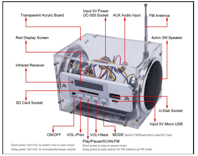
- ON/OFF Power
- Turn ON the work voltage if the Toggle Switch turns to ON/right status.
- Turn OFF the work voltage if the Toggle Switch turns to OFF/left status. Note: it just turns off the screen and speaker, but it is still working and continuously slightly depleting battery power.
- MP3 Mode
- Insert a U-disk or SD card, and the receiver automatically recognizes and starts playing internal MP3 music filfromfromfor the U-disk or SD card.
- Button ‘V-’ : Click to switch Previous music and keep pressing to decrease the volume.
- Button ‘P/P’: Press to stop playing and press again to start playing.
- Button ‘V+’: Click to switch Next music and keep pressing to increase the volume.
- Button ‘MODE’: Select audio sources as follows: Bluetooth/FM/AUX/U-disk/SD Card.
- Note: U-disk/AUX/SD card has a higher priority than Bluetooth and FM. So it will play music from the U-disk/AUX/SD card automatically after connecting the U-disk/AUX/SD card. But the user can also switch audio source with a button.
- The screen will display the music playing time for the current playing music at the U-disk and SD card modes. Restart displaying time if playing the next music.
- Display ‘AUX’ and ‘AUH’ for AUX mode;
- Display ‘USB’ in the left upper corner and the playing time.
- Display ‘SD’ in the lower left corner and the playing time.
- It can be controlled by buttons or an Infrared Remote Controller.
- FM Mode
- Select FM Mode by button the ‘Mode’ as display the current FM frequency.
- Button ‘V-’ : Click to switch to the previously saved FM radio stations and keep pressing to decrease volume.
- Button ‘P/P’: Click to play/pause and keep pressing to search for radio stations and save them.
- Button ‘V+’: Click to switch next saved FM radio station and keep pressing to increase volume.
- AUX Mode
- Select AUX Mode by button ‘Mode’. It is also called LINE mode, which needs an input R/L/GND audio signal.
- Its adjustment method is the same as MP3 Mode.
- Bluetooth Mode
- Select Bluetooth Mode by button the ‘Mode’ as display ‘BLUE’.
- Search for and connect the Bluetooth device ‘ZTV-CT02EA’ on your phone.
- Button ‘V-’ : Click to switch Previous music and keep pressing to decrease the volume.
- Button ‘P/P’: Press to stop playing and press again to start playing.
- Button ‘V+’: Click to switch Next music and keep pressing to increase volume.
- Answer Phone Calls: Click the Button ‘P/P’ to answer phone calls in Bluetooth Mode if there is a call.
- Reject Calls: Keep pressing the Button ‘P/P’ to reject phone calls in Bluetooth Mode if there is a call. 5.8>.Hang up the phone: Click the Button ‘P/P’ to hang up the phone at Bluetooth Mode during a call.
- Not all buttons are not available when playing the built-in voice prompt tone.
- It can be controlled by buttons or an Infrared Remote Controller.
Component Listing
NO. | Component Name | PCB Marker | QTY |
1 | Speaker Holder |
| 2 |
2 | Speaker Cover |
| 2 |
3 | Speaker |
| 2 |
4 | XH2.54-2P Wire | 15cm | 3 |
5 | XH2.54-3P Wire | 10cm | 1 |
6 | Random ColorWire | 10cm | 3 |
7 | DC-005 Power Socket |
| 1 |
8 | AUX Socket |
| 2 |
9 | BL-5C Battery Box |
| 1 |
10 | BL-5C Battery Rechargeable | 4.2V | 1 |
11 | FM Bluetooth Receiver |
| 1 |
12 | FM Antenna |
| 1 |
13 | Silicone SeatCushion |
| 4 |
14 | Infrared Remote Controller |
| 1 |
15 | AUX Audio Wire |
| 1 |
16 | 4.2V Battery Charger |
| 1 |
17 | USB-DC005 Power Wire |
| 1 |
18 | Transparent Acrylic Board |
| 6 |
19 | M2*10mm Screw |
| 22 |
20 | M2 Nut |
| 22 |
Application
- Training in welding skills
- Student school
- DIY production
- Project Design
- Electronic competition
- Gift giving
- Crafts collection
- Home decoration
- Souvenir collection
- Graduation design
- Holiday gift
Installation Steps
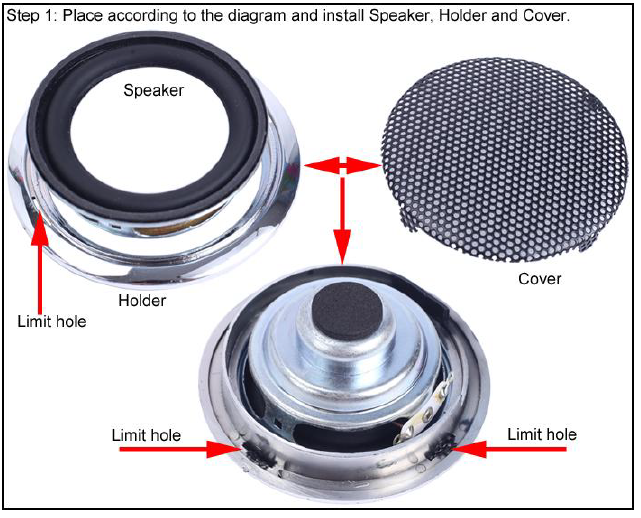
- Step 1: Place according to the diagram and install the Speaker, Holder, and Cover.
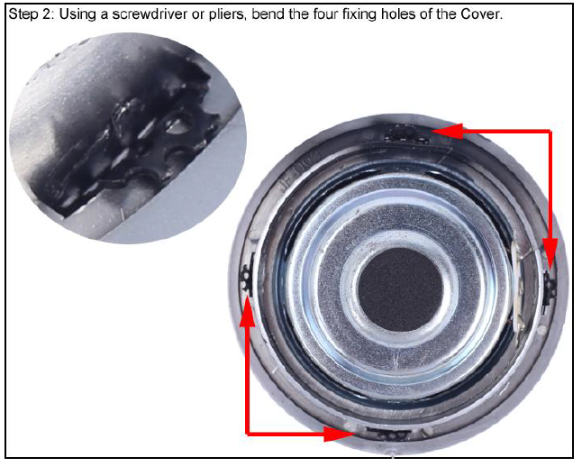
- Step 2: Using a screwdriver or pliers, bend the four fixing holes of the Cover.
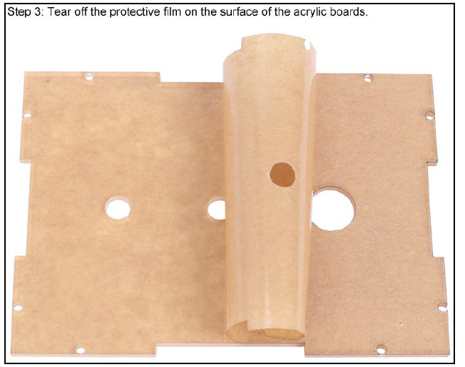
- Step 3: Tear off the protective film on the surface of the acrylic boards.
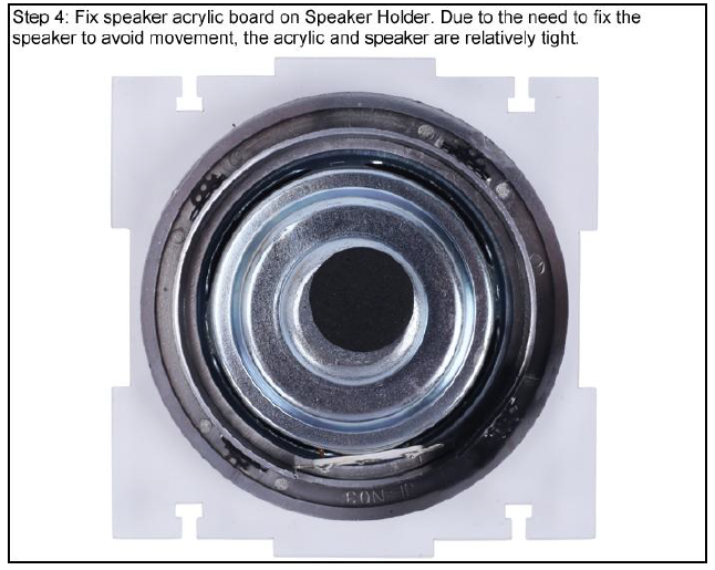
- Step 4: Fix the speaker acrylic board on the Speaker Holder. Due to the need to fix the speaker to avoid movement, the acrylic and the speaker are relatively tight.
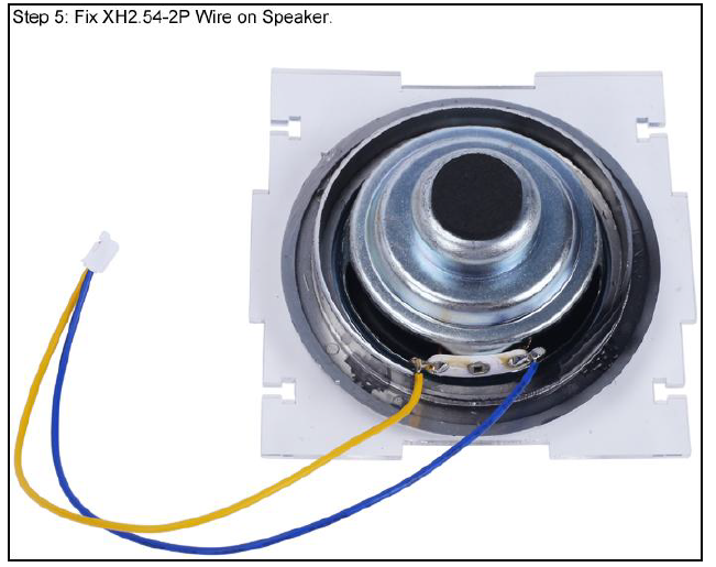
- Step 5: Fix XH2.54-2P Wire on Speaker.
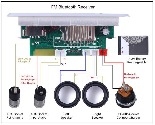
- Step 6: Fix 3pcs 10cm Wire on the FM Bluetooth Receiver. Tips: Red wire connects to ‘5V’ pad; Black wire connects to ‘GND’ pad; Yellow wire connects to ‘ANT’ pad.
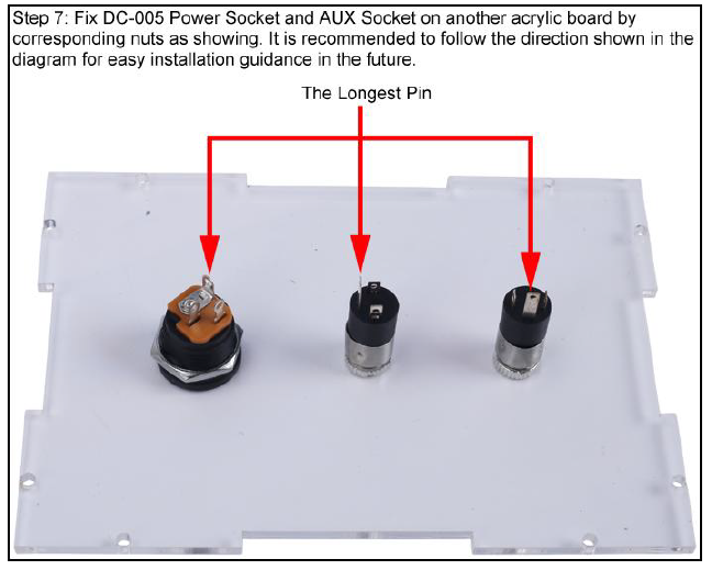
- Step 7: The ix DC-005 Power Socket and the AUX Socket on another acrylic board by corresponding nuts as shown. It is recommended to follow the direction shown in the diagram for easy installation guidance in the future.
- Step 8: Connect the H2.54-3P Wire in the middle AUX Socket as shown. Note: The Red wire connects to the longest pin. Yellow and black wires can be connected arbitrarily.
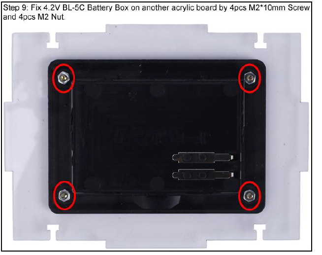
- Step 9: Fix the 4.2V BL-5C Battery Box on another acrylic board with pcs M2*10mm Screw and 4pcs M2 NuNut.
- Step 10: Fix XH2.54-3P Wire on 4.2V BL-5C Battery Box. Pay attention to the position of the red and black wires.
- Step 11: Fix the FM Bluetooth Receiver on another acrylic board bwithScrew and a Nut.
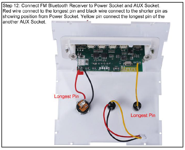
- Step 12: Connect the FM Bluetooth Receiver to the Power Socket and the AUX Socket. The red wire connects to the longest pin and the d black wire connects to the shorter pin, as shown position from the Power Socket. The yellow pin connects to the longest pin of the another AUX Socket.
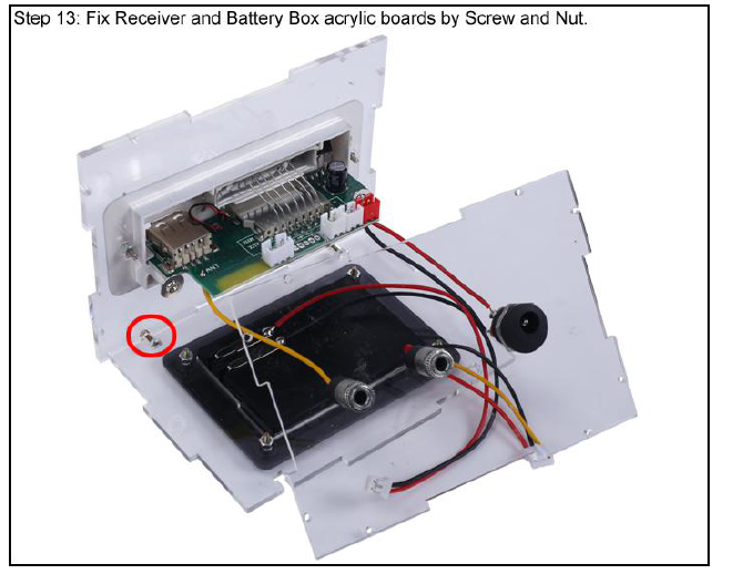
- Step 13: Fix the Receiver and Battery Box acrylic boards with the Screw and Nut.
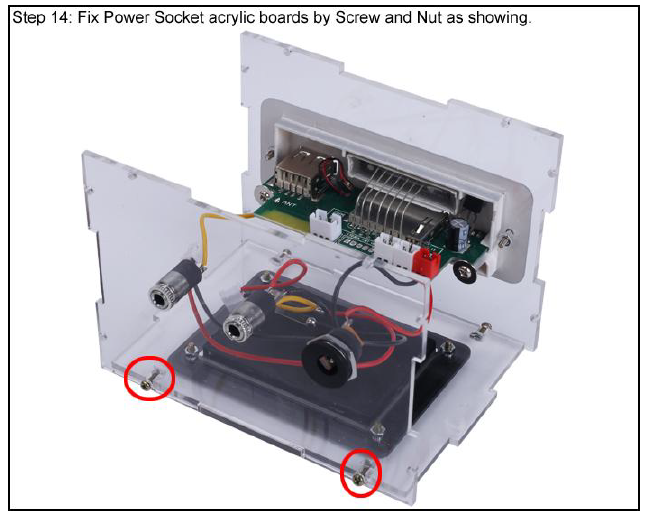
- Step 14: Fix the Power Socket acrylic boards with a Screw and Nut as shown.
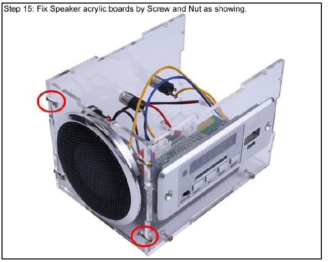
- Step 15: Fix the Speaker acrylic boards with a Screw and Nut as shown.
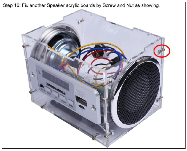
- Step 16: Fix another Speaker acrylic board with a Screw and a Nut as shown.
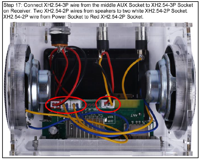
- Step 17: Connect the XH2.54-3P wire from the middle AUX Socket to the XH2.54-3P Socket on the Receiver.
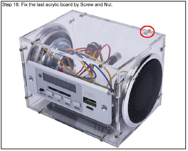
Two XH2.54-2P wires from speakers to two white XH2.54-2P sockets. XH2.54-2P wire from Power Socket to Red XH2.54-2P Socket. - Step 18: Fix the last acrylic board with a Screw and a Nut.
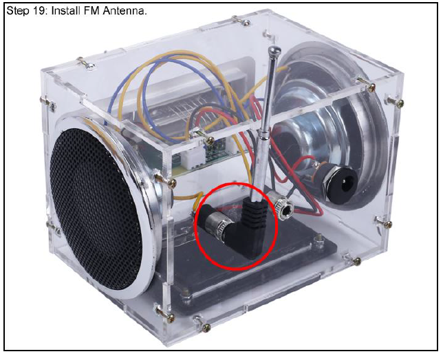
- Step 19: Install FM Antenna.
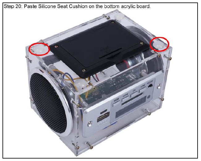
- Step 20: Paste the Silicone Seat Cushion on the bottom acrylic board.



Faqs
Can I connect my phone to Bluetooth Amplifier Audio Speaker via Bluetooth?
Yes, this DIY kit Bluetooth amplifier audio speaker supports Bluetooth connectivity for wireless audio streaming.
Is the amplifier module included in the kit?
Yes, the kit includes an amplifier module for enhanced sound quality.
What is the power output of Bluetooth Amplifier Audio Speaker ?
The power output of this speaker is 10W.
What is the frequency response range of Bluetooth Amplifier Audio Speaker ?
The frequency response range is 20Hz to 20kHz.
What is the Bluetooth version supported?
The Bluetooth version supported is 5.0.
What is the input voltage required?
The input voltage required is 5V DC.
What is the speaker impedance?
The speaker impedance is 4-8 ohms.
Is the enclosure of Bluetooth Amplifier Audio Speaker customizable?
Yes, the enclosure is customizable, allowing you to personalize the look of the speaker.
Are the assembly instructions included?
Yes, the kit comes with step-by-step instructions for easy assembly.
Is Bluetooth Amplifier Audio Speaker kit suitable for beginners?
Yes, Bluetooth Amplifier Audio Speaker kit is suitable for both beginners and experienced DIY enthusiasts.
Leave a Comment