Grizzly Combo Sander G1276 Instruction Manual | Setup Instructions
Content
Introducing the Grizzly Combo Sander G1276
The G1276 is a robust and versatile tool designed for both professional woodworkers and DIY enthusiasts. Featuring a combination of a belt and disc sander, it allows for efficient sanding of various materials with precision. The machine is built for durability and ease of use, making it ideal for a range of projects. With an approximate cost of $499, it provides excellent value for those seeking quality in their woodworking tools.
Detailed Specifications
The Grizzly Combo Sander G1276 comes with the following detailed specifications:
- 1/3 HP motor with 120V, 60Hz single-phase motor.
- Variable speed dial ranging from 1,400 to 2,400 RPM.
- 14,000 to 24,000 orbits per minute (OPM).
- 5-inch disc sander with a 2.5-amp motor.
- 6-inch random orbital sander with a 3-amp motor.
- Dust collection system with a 1.5-inch diameter port.
- Micro-adjustment feature for precise sanding.
- Weighs approximately 15 pounds.
MAIN UNIT PARTS DIAGRAM
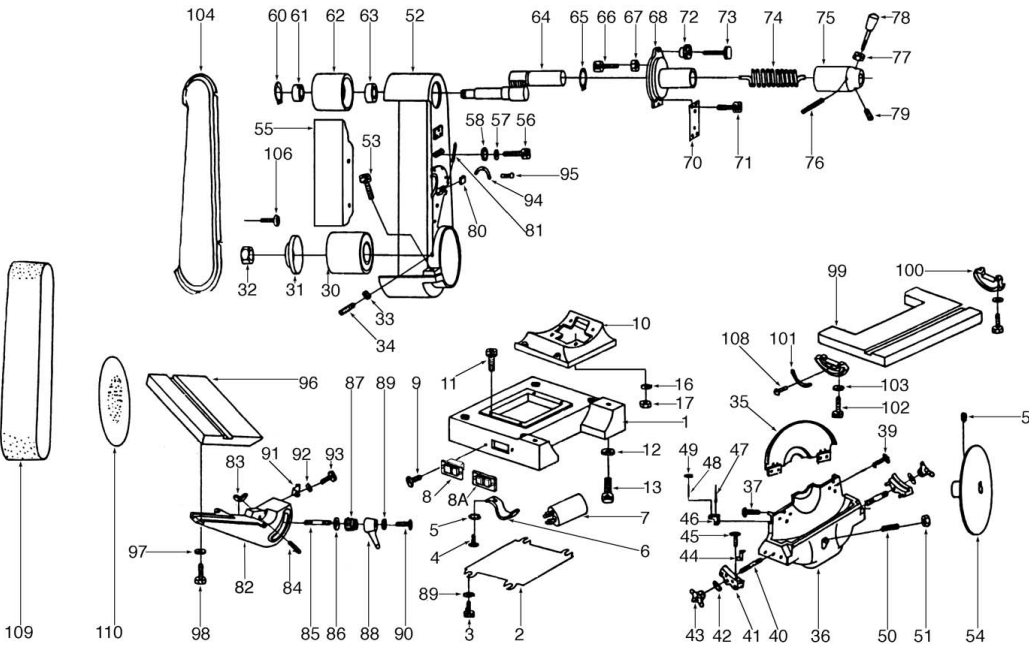
PARTS LIST
001 | P1183001 | STAND |
002 | P1183002 | BASE PLATE |
003 | PB17M | HEX BOLT M8-1.25 X 16mm |
004 | P1183004 | COVER SCREW |
005 | PW03 | FLAT WASHER #10 |
006 | P1183006 | COVER LOCK |
007 | PC400B | CAPACITOR-BIG OD |
008 | P1019090A | SWITCH |
008A | P1019090B | PLASTIC SWITCH COVER |
009 | P1183009 | SWITCH SCREW |
010 | P1183010 | MOTOR BASE |
011 | PSB11M | CAP SCREW M8-1.25x 16mm |
012 | PLW05 | LOCK WASHER 7⁄16" |
013 | PSB13 | CAP SCREW 7⁄16"-14 x 11⁄4" |
014 | P1183014 | STATOR HOUSING |
015 | PB07 | HEX BOLT 5/16"-18 x 3/4" |
016 | PLW01 | LOCK WASHER 5⁄16" |
017 | PN02 | HEX NUT 5⁄16"-18 |
018 | P1183018 | STATOR |
019 | P1183019 | SHAFT |
020 | PK13M | KEY 5 x 5 x 70 mm |
021 | PK12M | KEY 5 x 5 x 30 mm |
022 | P6206 | BALL BEARING 6206 |
023 | P1183023 | RIGHT CASTING COVER |
024 | PS19 | PHLP HD SCR 1⁄4"-20 x 1" |
025 | PLW02 | LOCK WASHER 1⁄4" |
026 | P6206 | BALL BEARING 6206 |
027 | P1183027 | LEFT CASTING COVER |
028 | PCP004 | CONTACT PLT, LG, INT PT |
029 | P1183029 | CENTRIFUGAL SWITCH |
030 | P1183030 | LOWER WHEEL |
031 | P1183031 | FLANGE |
032 | P1183032 | 1"-8 LH HEX NUT |
033 | PN01M | HEX NUT M6-1.0mm |
034 | PSS12M | SET SCREW M6-1.0x 25mm |
035 | P1183035 | DISC GUARD |
036 | P1183036 | BASE |
037 | PS06 | PHLP HD SCR 10-24 x 3⁄8" |
039 | PS06 | PHLP HD SCR 10-24 x 3⁄8" |
040 | P1183040 | STUD |
041 | P1183041 | SLIDING RAIL |
042 | PW04 | FLAT WASHER 7⁄16" |
043 | P1183043 | STAR KNOB |
044 | P1183044 | POINTER |
045 | P1183045 | SPECIAL SCREW |
046 | P1183046 | BLOCK |
047 | PRP32M | ROLL PIN 6 x 40mm |
048 | PSS12M | SETSCREW M6-1.0 x 25mm |
049 | PN01M | HEX NUT M6-1.0 |
050 | PSS18 | SETSCREW 5⁄16"-18 x 3⁄4" |
051 | PN02 | HEX NUT 5⁄16"-18 |
052 | P1183052 | BELT HOUSING CASTING |
053 | PSB12M | CAP SCREW M8-1.25x 40mm |
054 | P1183054 | ALUMINUM DISC |
055 | P1183055 | PLATEN |
056 | PSB13M | CAP SCREW M8-1.25x 30mm |
057 | PW07 | FLAT WASHER 5⁄16" |
058 | PW04 | FLAT WASHER 7⁄16" |
059 | PSS01M | SET SCREW M6-1.0x 10mm |
060 | PR05M | EXT RETAINING RING 15mm |
061 | P6202` | BALL BEARING 6202 |
062 | P1183062 | UPPER WHEEL |
063 | P6203 | BALL BEARING 6203 |
064 | P1183064 | SHAFT |
065 | PR10M | EXT RETAINING RING 22mm |
066 | PSB01M | CAP SCREW M6-1.0x 16 |
067 | PN01M | HEX NUT M6-1.0 |
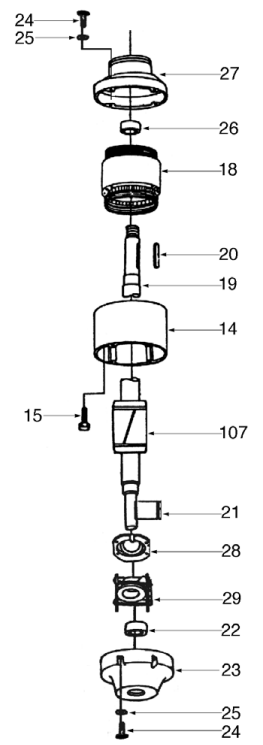
MOTOR UNIT PARTS DIAGRAM
068 | P1183068 | COVER |
070 | P1183070 | PLATE |
071 | PSB14M | CAP SCREW M8-1.25x 20 |
072 | P1183072 | KNURLED CHECK NUT |
073 | P1183073 | KNURLED BOLT |
074 | P1183074 | SPRING |
075 | P1183075 | LEVER HOLDER |
076 | PRP33M | ROLL PIN 6 x 50mm |
077 | PN08 | HEX NUT 3⁄8"-16 |
078 | P1183078 | IDLER PULLEY LEVER |
079 | PSS01M | SETSCREW M6-1.0 x 10mm |
080 | P1183080 | BLOCK |
081 | PRP33M | ROLL PIN 6 x 50 |
082 | P1183082 | TRUNNION |
083 | P1183083 | SLIDE |
084 | PRP19M | ROLL PIN 4 x 14mm |
085 | P1183085 | STUD |
086 | PW04 | FLAT WASHER 7⁄16" |
087 | P1183087 | TOOTHED NUT |
088 | P1024039 | LOCK HANDLE |
089 | PLW02 | LOCK WASHER 1⁄4" |
090 | PB02 | HEX BOLT 1⁄4"-20 x 5⁄8" |
091 | P1183044 | POINTER |
092 | PW03 | FLAT WASHER #10 |
093 | PS18 | PHLP HD SCR 10-24 1⁄4" |
094 | P1183094 | DEGREE SCALE |
095 | P1183108 | RIVET |
096 | P1183096 | BELT SANDER TABLE |
097 | PW07 | FLAT WASHER 5⁄16" |
098 | PB07 | HEX BOLT 5⁄16"-18 x 3⁄4" |
099 | P1183099 | DISC SANDER TABLE |
100 | P1183100 | DEGREE SLIDE |
101 | P1183101 | DEGREE SCALE |
102 | PB07 | HEX BOLT 5⁄16"-18 x 3⁄4" |
103 | PW07 | FLAT WASHER 5⁄16" |
104 | P1183104 | BELT GUARD |
106 | P1183106 | SPECIAL SCREW |
107 | P1183019 | SHAFT |
108 | P1183108 | RIVET |
109 | G1215 | SANDING BELT 6" x 48" 100GT |
110 | G1221 | SANDING DISC 12" 100 GT |
112 | P1183112 | MOTOR FAN |
113 | P1183113 | COMPLETE MOTOR 3450 RPM |
113 | P1276113 | COMPLETE MOTOR 1720 RPM |
CIRCUIT REQUIREMENTS
110/220V Operation
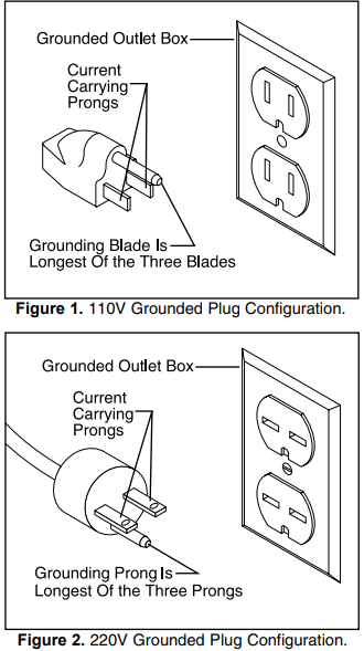
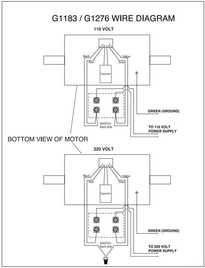
The Model G1183/1276 is prewired for 110V, single-phase operation. Figure 1 depicts the typical grounded receptacle which should be used. This machine can be rewired to operate at 220V, however, a different plug will need to be installed. Figure 2 shows a typical 220V plug. A wiring diagram is provided at the back of the manual to show the two wiring configurations.
Grounding
In the event of an electrical short, grounding reduces the risk of electric shock by providing a path of least resistance to disperse electric current. This tool is equipped with a power cord having an equipment-grounding conductor. See Figure 1. The outlet must be properly installed and grounded in accordance with all local codes and ordinances.
WARNING
This equipment must be grounded. Verify that any existing electrical outlet and circuit you intend to plug into is actually grounded. If it is not, it will be necessary to run a separate 12 A.W.G. copper grounding wire from the outlet to a known ground. Under no circumstances should the grounding pin from any three-pronged plug be removed. Serious injury may occur.
Fusing Grizzly Combo Sander G1276
The 1 HP motor will draw 12 amps at 110V and 6 amps at 220V. A 15-amp fuse or circuit breaker should be used when fusing this combination sander. Circuits rated any higher are not adequate to protect the motor from power surges. If you operate this sander on any circuit that is already close to capacity, it might trip the breaker or blow the fuse. However, if an unusual load does not exist, and the circuit protection is still activated, you should have the circuit inspected by a qualified electrician.
Extension Cords
If you find it necessary to use an extension cord with the Model G1183/1276, make sure the cord is rated Hard Service (grade S) or better. Refer to the chart in the standard safety instructions to determine the minimum gauge for the extension cord. The extension cord must also contain a ground wire and plug pin. Always repair or replace extension cords when they become worn or damaged.
Wiring Diagram
Your G1183/1276 machine comes pre-wired for 110-volt operation. A wiring diagram is provided at the back of this manual should it be necessary to repair or revise the wiring. Always utilize a qualified electrician when doing any electrical work on this equipment.
CAUTION
We have covered some basic electrical requirements for the safe operation of your Sander. These requirements are not necessarily comprehensive. You must be sure that your particular electrical configuration complies with local and state codes. Ensure compliance by checking with your local municipality or a licensed electrician.
GENERAL INFORMATION
Commentary
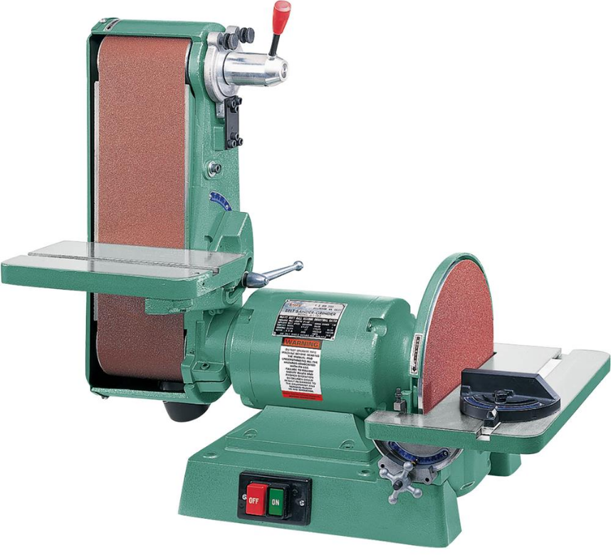
- Grizzly Industrial, Inc. is proud to offer the Model G1183 6" x 48" – 12" Disc Combination Sander and its slower-speed version, the Model G1276. This sander is part of Grizzly’s growing family of fine woodworking machinery. When used according to the guidelines set forth in this manual, you can expect years of trouble-free, enjoyable operation, and proof of Grizzly’s commitment to customer satisfaction.
- The Model G1183 and Model G1276 feature heavy-duty cast-iron bodies and tilting tables, and powerful 1 HP single-phase motors. The Model G1183 provides 3,450 R.P.M. disc rotation and a 5,000 F.P.M. belt speed. The Model G1276 produces a 1,725 R.P.M. disc rotation and a 2,500 F.P.M. belt speed. Both models have 3" dust ports attached. These sanders come prewired and ready to operate at 110V.
- Both models offer a wide 6" belt surface for fast stock removal and a 12" disc for convenient shaping. Fully adjustable tables allow sanding at a variety of angles.
- We are also pleased to provide this manual with the G1183 and G1276. This instruction manual was written to guide you through assembly, review safety considerations, and cover general operating procedures. It represents our latest effort to produce the best documentation possible. If you have any criticisms that you feel we should pay attention to in our next printing, please write to us at the address shown to the right.
- To operate this or any power tool safely and efficiently, it is essential to become as familiar with its characteristics as possible. The time you invest before you begin to use your Model G1183/1276 will be time well spent. DO NOT operate this machine until you are completely familiar with the contents of this manual. Make sure you read and understand all of the safety procedures. If you do not understand something, DO NOT operate the machine.
Unpacking
The Combination Sander is shipped from the factory in a carefully packed carton. If you find the machine to be damaged after you’ve signed for delivery and the truck and driver are already gone, you will need to file a freight claim with the carrier. Save the containers and all packing materials for inspection by the carrier or their agent. Without the packing materials, filing a freight claim can be difficult. If you need advice regarding this situation, please call us.
WARNING
The G1183/1276 is a fairly heavy machine (155 lbs.). DO NOT over-exert yourself while unpacking or moving your machine – get assistance. In the event that your Combination Sander must be moved up or down a flight of stairs, be sure that the stairs are capable of supporting the combined weight of people and the machine. Serious personal injury may occur.
When you are completely satisfied with the condition of your shipment, you should inventory its parts.
NOTICE
Please keep all packaging materials until you are satisfied that the machine is in good condition. Should you need to file a freight claim, the carrier’s agent will require inspection of those materials. Settling a claim can be difficult if packaging is not available.
Piece Inventory
With all the parts removed from the container, you should have components as listed below and shown in Figure 3:
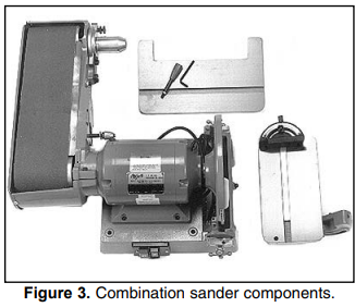
- Motor Body and Belt Assembly
- Disc Table
- Belt Table
- Allen Wrench
- Miter Gauge
- Handle
If anything is missing, call or write to the appropriate service department listed in the General Information section. If anything is damaged, please follow the procedures described to the left.
NOTICE
Ensure that the Model G1183/G1276 is located on a flat, level surface. This will maximize the stability of the machine and ensure that adjustments are accurate. For conditions where permanent mounting is possible, we recommend bolting the Combination Sander to your bench top or work table. This type of mounting will minimize vibration and provide a more stable work environment.
Clean Up
The unpainted surfaces are coated with a waxy oil to protect it from corrosion during shipment. Remove this protective coating with a solvent cleaner or citrus-based degreaser. Avoid chlorine-based solvents as they may damage painted surfaces should they come in contact. Always follow the usage instructions on the product you choose for clean up.
CAUTION
Many of the solvents commonly used to clean machinery can be highly flammable and toxic when inhaled or ingested. Always work in well-ventilated areas far from potential ignition sources when dealing with solvents. Use care when disposing of waste rags and towels to be sure they do not create fire or environmental hazards. Keep children and animals safely away when cleaning and assembling this machine.
WARNING
Do not use gasoline or other petroleum-based solvents to remove this protective coating. These products generally have low flash points which makes them extremely flammable. A risk of explosion and burning exists if these products are used. Serious personal injury may occur.
CAUTION
All die-cut metal parts have a sharp edge (called “flashing”) on them after they are formed. This is generally removed at the factory. Sometimes a bit of flashing might escape inspection, and the sharp edge may cause cuts or lacerations when handled. Please examine the edges of all die-cut metal parts and file or sand the edge to remove the flashing before handling.
Site Considerations
Bench Load
The G1183/1276 Combination Sander represents a moderately large weight load in a small footprint. Most commercial or home shop benches should be sufficient to carry the weight of the machine. If you question the strength of your workbench, you can opt to reinforce it, or consider placing the sander on a freestanding bench such as the Shop Fox® Deluxe Tool Table.
Working Clearances
Working clearances can be thought of as the distances between machines and obstacles that allow safe operation of every machine without limitation. Consider existing and anticipated machine needs, the size of material to be processed through each machine, and space for auxiliary stands and/or work tables. Also, consider the relative position of each machine to one another for efficient material handling. Be sure to allow yourself sufficient room to safely run your machines in any foreseeable operation.
Lighting and Outlets
Lighting should be bright enough to eliminate shadow and prevent eye strain. Electrical circuits should be dedicated or large enough to handle combined motor amp loads. Outlets should be located near each machine so power or extension cords are not obstructing high-traffic areas. Be sure to observe local electrical codes for proper installation of new lighting, outlets, or circuits.
CAUTION
Make your shop “child safe.” Ensure that your workplace is inaccessible to youngsters by closing and locking all entrances when you are away. Never allow visitors in your shop when assembling, adjusting, or operating equipment.
Description
The Grizzly Combo Sander G1276 is a 2-in-1 sanding tool that includes a 5-inch disc sander and a 6-inch random orbital sander. The disc sander is ideal for sanding flat surfaces, while the random orbital sander is suitable for contoured surfaces. The variable speed dial allows for precise control over sanding speed, while the micro-adjustment feature ensures accurate sanding. The dust collection system helps keep your workspace clean and free of debris. With its powerful motor and durable construction, the Grizzly Combo Sander G1276 is an excellent addition to any woodworking or metalworking shop.
ASSEMBLY
Assembly Basics
Most of your Combination Sander has been assembled at the factory. There are several sim-ple steps to follow to complete the assembly. A few common tools will be required for assembly: Screwdrivers - medium and large straight blade or Phillips, Allen wrenches - 2mm, 3mm, 6mm and open end wrenches - 8mm and 10mm.
Belt Table
The belt table adjusts to allow you to sand your work at angles from -30° up to 45°. To make assembly easier, we recommend you mount the Combination Sander on a table or bench before assembling. Four bolt holes are included on the sander’s base for mounting.
To attach the belt table:
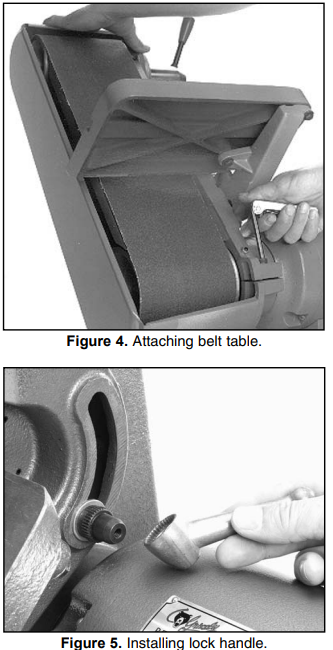
- Swing the belt assembly to its vertical posi-tion by loosening the 6mm Allen® capscrew shown in Figure 4. Tighten capscrew to hold the belt assembly in this position.
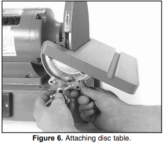
- Remove the lock handle assembly and the threaded stud from the belt housing using a large flat bladed screwdriver.
- Line up the belt table trunnion with the slot in the belt assembly bracket. Reinstall the threaded stud, then install the flat washer, toothed nut, lock handle, lock washer and bolt, as shown in Figure 5. Make sure the handle is installed so the table can be loos-ened and tightened without interfering with other components. The belt table’s tight fit is deliberate. Placing the table in position is easier if you swing the belt table so the 45°positive stop bolt is located over the gap in the motor casting cover.
Disc Table
The disc table adjusts to allow you to sand your work at angles from -20° up to 45°. To install the disc table:
- Loosen the two star knobs at either end of the disc table base until they reach the ends of their threaded rods.
- Move the sliding rails and the washers to allow enough room for the table to be installed.
- Flip the 90° stop block out of position.
- Install table securely between the two slid-ing rails as shown in Figure 6.
- Tighten star knobs to secure the table in position.
Grizzly Combo Sander G1276 Belt Lever
The belt lever is used for releasing the tension on the idler pulley for belt installation.
To attach the belt lever:
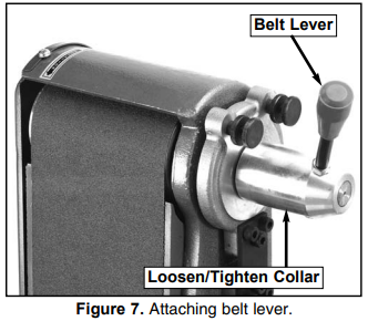
- Thread the belt lever onto the loosen/tighten collar and secure with the checknut. See Figure 7.
WARNING: DO NOT attempt to operate this machine before completing the assembly and adjust-ment instructions. Be sure that the switch is off and the cord is disconnected from the power source at all times until assembly and adjustment are complete and you have reviewed all safety guidelines. Serious injury could occur.
NOTICE
After all parts have been assembled, dou-ble-check the entire machine to make sure all fasteners are tight.
ADJUSTMENTS
Proper adjustment of the Combination Sander is essential to ensure its optimum performance. The adjustments covered in this section are easily accomplished.
Tables
Tables should be square in both planes to exe-cute precise work. Procedures for accomplishing this are described below.
- Adjust the miter gauge to 90°. You can use it as a reference point from which to make other adjustments.
Place the miter gauge in the table slot and, with a high-quality machinist’s or combina-tion square against the face of the miter gauge, check the tables for squareness against the sanding surfaces. See Figures 8 and 9.
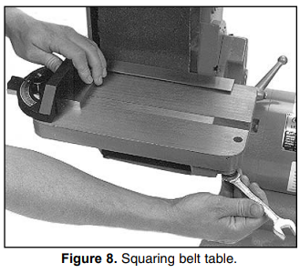
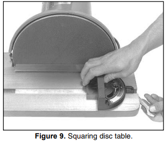
- If either table is out of square, loosen the bolts that attach the table to the trunnion and adjust the table until it is square to the disc or belt. Tighten the table and re-inspect results.
Positive Stops
Positive stops are used to move the tables to dif-ferent positions quickly, without measurement. The belt table has two positive stops (one at 45°and one at 90°) and the disc table has one (at 90°).
To Adjust the Belt Table Positive Stops:
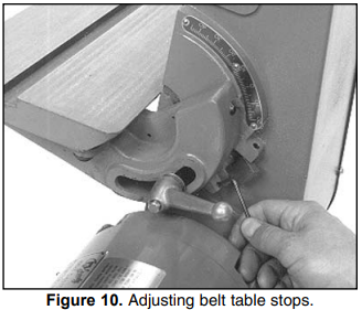
- Loosen the lock handle.
- Flip block into the 90° position.
- Use a square to verify the accuracy to the stop.
- If the stop is engaged and the table isn’t quite perpendicular to the belt, adjust the stop by turning the setscrew in or out as needed. See Figure 10.
- Flip the block back to its former position, then back to 90° to double-check accuracy.
- Repeat this procedure with the 45° stop.
You’ll need a known 45° angle, such as a speed square or the head of a combination square to check accuracy.
To Adjust the Disc Table Positive Stops:
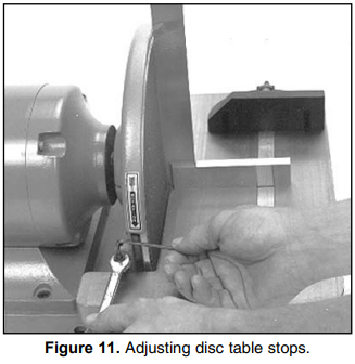
- Loosen both star knobs.
- Flip block over table.
- Loosen check nut.
- Place accurate square on table and against disc as shown in Figure 11.
- Make fine adjustments by turning the setscrew in or out. Secure the checknut.
Belt Platen
The belt platen should be adjusted out far enough so it is flush with, or slightly higher than the upper roller. The rollers are slightly crowned, that is they are higher in the center than at the edges. This crowning helps the belt to stay centralized on the rollers. The adjustment of the platen to the roller should be done at the high point, or center, of the roller.
- Loosen the cap screw on the side of the belt housing with a 6mm Allen® wrench. This frees the in and out movement of the belt platen
- Use a straightedge positioned in the center of the platen which extends over the upper roller. Adjust the belt platen in and out until the straightedge is just barely lifted off of the idler roller.
- Tighten cap screw.
WARNING: DO NOT attempt to operate this machine before completing the assembly and adjust-ment instructions. Be sure that the switch is off and the cord is disconnected from the power source at all times until assembly and adjustment are complete and you have reviewed all safety guidelines. Serious injury could occur.
Disc Guard
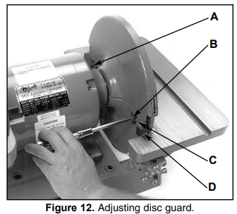
- Loosen the two screws (A and B) shown in Figure 12. These screws hold the guard in place.
- Adjust the two vertically-aligned screws (C and D in Figure 12) so the guard is upright and not touching the disc. The top screw moves the guard toward the disc and the bottom screw moves it away from the disc.
- Rotate the disc by hand to see if the disc scrapes against the guard; repeat Steps 1 and 2, if needed.
- Tighten screws C and D to secure guard.
WARNING
Operating this equipment has the potential to propel debris into the air which can cause eye injury. Always wear safety glass-es or goggles when operating equipment. Everyday glasses or reading glasses only have impact resistant lenses, they are not safety glasses. Be certain the safety glass-es you wear meet the appropriate stan-dards of the American National Standards Institute (ANSI).
Belt Arm Movement
The 6" x 48" Belt Arm can be locked at any angle between horizontal and vertical for a variety of sanding applications.
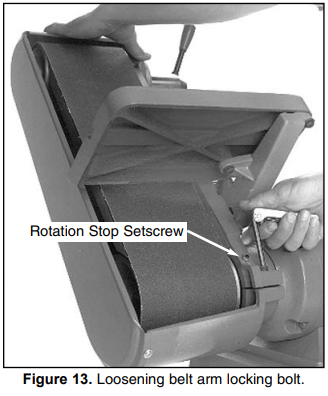
- Loosen the locking bolt as shown in Figure 13.
- Grab the top of the belt arm housing and move the belt arm to the desired position.
- Tighten the locking bolt.
The setscrew/checknut combination shown in Figure 13 acts as a stop for the rotation of the belt arm. If it ever becomes necessary to remove the belt arm from the motor, be sure to remove this setscrew to allow the arm housing to be slipped of the motor mounting.
Belt Installation
The 6'' x 48'' sanding belt is easily installed. First remove the belt guard by loosening the four com-bination-head screws. Pull down on the spring loaded belt tensioning lever which lowers the upper roller and allows the belt to be slid off of the two rollers. See Figure 14.
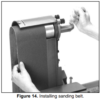
The new belt will have a rotation arrow on the backing. Make certain the belt is placed onto the rollers in the proper orientation. There is a rota-tion label on the housing indicating the direction. Pull the lever down and slide the new belt onto the rollers and center it.
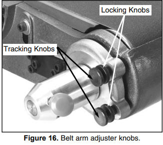
Belt Tracking
Tracking adjustment is conducted as follows:
Insure that the upper roller is parallel to the platen (there is no adjustment for the lower roller). This adjustment is easier to accom-plish with the belt removed. Remember that the roller is crowned, and a rough align-ment of the roller to the platen was already described in the section entitled Belt Platen. To determine parallelism for proper tracking, measure at a point approximately .5'' from the ends of the roller. Use a straight edge on top of the platen and extend it over the roller. See Figure 15.
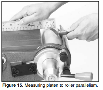
- You should see a gap between the straight edge and roller. Measure this with a feeler gauge.
- Repeat step 1 and 2 with the straight edge positioned at the opposite edge of the platen.
- The difference in the measurements is the amount of "twist" in the belt. Reduce the twist by adjusting one of the two tracking knobs. See Figure 16. If the "out-board" end (or the end furthest from the tracking adjustment side) of the roller measures greater than the "in-board" side, tighten the right hand tracking knob
- With the straightedge along the edge which is low, loosen the knurled locking nut and turn the tracking knob while watching the gap change between the straight edge and the roller. Make small changes and check for a change in gap on the opposite side.
- When the gap has been equalized between the two sides, make sure the center of the roller, or the crown, is still approximately flush or just slightly above the platen sur-face. Lock the adjustment knobs with the locking knobs.
- Reinstall the belt. Move the belt by hand (DO NOT turn on the power). If the belt tracks to one side or the other, adjust the idler roller slightly by backing off the locking knobs and turning the knurled adjustment screws in or out. See Figure 16. Make very small adjustments and move the belt by hand for a few revolutions to test the result. Keep readjusting until you are satisfied the belt is tracking properly when moved by hand.
Lock the adjustment in place by tightening the knurled lock knobs on both adjusters.
- Test the tracking by cycling the machine on and off very quickly. See if the belt stays centered during this test cycle. If the belt doesn’t remain centered on the rollers, it must be adjusted further.
CAUTION
Moving sanding discs and belts are danger-ously abrasive. Use extreme caution when working near sanding surfaces. Failure to exercise care while sanding could result in severe injury.
OPERATIONS
The aluminum disc accepts 12" diameter cloth or paper-backed PSA sanding discs. The belt sander requires a 6" x 48" sanding belt. For disc or belt sanding, we recommend a 100-grit (medi-um) material for general sanding chores, a 60-grit (coarse) material for rough work, and a 150-grit (fine) surface for finish work. See the current Grizzly catalog for prices and ordering informa-tion.
Please review all safety rules for sanders and all power tools before attempting operation. The hints listed below are also worth your considera-tion:
- When using the table for beveled sanding operations, try to keep an open table angle (90˚ or more). This eliminates the risk of getting the workpiece jammed between the disc (or vertical belt) and the table.
- The surface feet per minute of the spinning disc increases as you move from the center to the rim.
- When belt sanding, sand with the grain of the wood.
- Do not over-sand soft woods such as bass wood or pine.
- Choose the correct sanding grit for the job.
- Do not use the sander as a replacement for a bandsaw or a planer. It is designed for fin-ish work, not rough dimensioning.
- Keep your workpiece moving across the face of the disc or belt to prevent grooves or ruts in the surface you’re sanding.
Table Tilt of Grizzly Combo Sander G1276
The belt table can be adjusted from -30˚ to 45˚ and the disc table can go from -20˚ to 45˚ relative to the plane of the sanding surface. Both tables have positive stop blocks which will quickly posi-tion the table at the 90˚ and 45˚ angles. To adjust the tilt it is sometimes necessary to swing the stop block out of the way, move the table, swing the block back in, then contact the stop block. If angles other than the preset are desired, swing the stop out of the way and use the angle scale or a bevel gauge to set to the position needed. Lock the handle (on the belt table) or the star knob (on the disc table) firmly in position.
Whenever possible, sand with an open angle where there is plenty of clearance between the belt and the table. This will avoid getting the work-piece trapped between the sanding surface and the table.
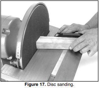
Disc Sanding
- Loosen table lock knob and tilt work table to desired angle. Tighten lock knob.
- Use miter gauge to guide work into position
Ease workpiece into the half of the disc that spins down toward the table. See Figure 17.
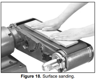
Surface Sanding
To remove a large amount of material quickly from a large surface area, use the belt arm in its horizontal position.
- Turn the sander on and let it reach its full working speed.
Place the workpiece flat on the belt. Be sure to hold the work securely with both hands. Place one hand at the end of the workpiece to feed it against the rotation of the belt. Place the other hand lightly on top of the workpiece to ensure adequate stock removal. See Figure 18.
WARNING: Operating this equipment has the potential to propel debris into the air which can cause eye injury. Always wear safety glass-es or goggles when operating equipment. Everyday glasses or reading glasses only have impact resistant lenses, they are not safety glasses. Be certain the safety glass-es you wear meet the appropriate stan-dards of the American National Standards Institute (ANSI).
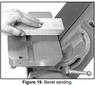
Bevel Sanding
When bevel sanding, be sure to re-position the work table so it is at a maximum of 1/16" away from the disc or belt.
- Hold workpiece against miter gauge to keep piece square to the disc or belt.
- Move workpiece against sanding surface width to ensure even abrasion. Use even, but firm, pressure.
When using the belt arm for bevel sanding, you will have greater control over your work if you tilt the belt arm and maintain the table at level. See Figure 19.
WARNING: DO NOT attempt to operate this machine before completing the assembly and adjust-ment instructions. Be sure that the switch is off and the cord is disconnected from the power source at all times until assembly and adjustment are complete and you have reviewed all safety guidelines. Serious injury could occur.
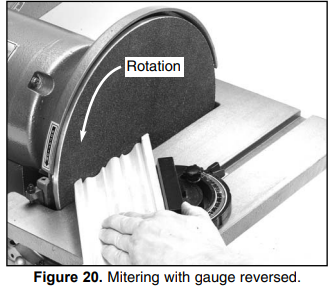
Miter Sanding
The most efficient way to get a perfect miter is to cut the workpiece slightly long and sand it to the desired dimension. Miter sanding can be done on either the belt or the disc.
- Loosen the knob on the miter gauge and adjust the angle to the desired point. Tighten the knob.
- Slide the miter gauge into its slot and use it to hold your workpiece in position. The miter gauge can be used in either direction in the slot to achieve the proper relation of the workpiece to the disc.
With light, but firm pressure, push the work-piece slowly into the downspin side of the rotating disc. See Figure 20.
Setup Guide
- Setting up the Grizzly Combo Sander G1276 is a straightforward process. Here are the steps to follow:
- Plug in the sander and turn on the power switch.
- Adjust the speed dial to the desired RPM.
- Attach the appropriate sanding disc or pad to the sander.
- Press the sander firmly onto the surface to be sanded and move it in a circular motion.
- To change the sanding disc or pad, turn off the sander, unplug it, and use the included wrench to loosen the disc holder.
MAINTENANCE
General
The Combination Sander is ruggedly constructed to provide years of dependable service. To ensure that you enjoy maximum performance and longevity, we suggest the following routine maintenance:
- Check all fasteners for tightness before each use. Tighten when necessary.
- Keep the Combination Sander clean for maximum efficiency and heat dissipation. Wipe away accumulated sanding dust and grime after each use.
- Inspect sanding disc and belt for excessive wear and damage. Replace if necessary.
- Inspect switches and cord periodically for wear or damage. Replace if necessary.
- Bearings are sealed and permanently lubri-cated, so no lubrication is needed. Check for wear periodically and replace when worn. Increased motor noise and vibration are both indicators of bearing w
- Inspect roller drive bearings for wear. Replace if needed.
Tables
The tables and other non-painted surfaces on the Model G1183 and G1276 should be protected against rust and pitting. Wiping the sander clean after every use ensures that moisture from wood dust isn’t allowed to trap moisture against bare metal surfaces.
Some woodworkers recommend using automo-tive paste wax on exposed steel and cast iron surfaces. The wax provides a layer of protection, as well as reducing friction between lumber and the table, making cuts faster and smoother. Avoid waxes that contain silicone or other synthetic ingredients. These materials can find their way into lumber that’s being worked, and can make staining and finishing difficult. If you use paste wax, make sure that it’s 100% Carnauba wax.
WARNING
DO NOT make adjustments or attempt any maintenance procedures while this machine is running. Ensure that the switch is off, power is disconnected and all mov-ing parts have stopped before making adjustments. Failure to do so could result in serious operator injury.
CLOSURE
The following pages contain general machine data, part diagrams/lists, troubleshooting guide and Warranty/Return information for your Model G1183/1276 Combination Sander.
If you need parts or help in assembling your machine, or if you need operational information, we encourage you to call our Service Department. Our trained service technicians will be glad to help you. If you have comments dealing specifically with this manual, please write to our Bellingham, Washington location using the address in Section 3: General Information. The specifications, draw-ings, and photographs illustrated in this manual represent the Model G1183/1276 as supplied when the manual was prepared. However, due to Grizzly’s policy of continuous improvement, changes may be made at any time with no oblig-ation on the part of Grizzly. Whenever possible, though, we send manual updates to all owners of a particular tool or machine. Should you receive one, add the new information to this manual and keep it for reference.
We have included some important safety mea-sures that are essential to this machine’s opera-tion. While most safety measures are generally universal, Grizzly reminds you that each work-shop is different and safety rules should be con-sidered as they apply to your specific situation.
We recommend you keep a copy of our current catalog for complete information regarding Grizzly's warranty and return policy. If you need additional technical information relating to this machine, or if you need general assistance or replacement parts, please contact the Service Department listed in Section 3: General Information.
Additional information sources are necessary to realize the full potential of this machine. Trade journals, woodworking magazines, and your local library are good places to start.
WARNING
The Model G1183/1276 was specifically designed for wood sanding. DO NOT MODIFY AND/OR USE THIS MACHINE FOR ANY OTHER PURPOSE. Modifications or improper use of this tool will void the war-ranty. If you are confused about any aspect of this machine, DO NOT use it until you have answered all your questions. Serious person-al injury may occur.
Like all power tools, there is danger associ-ated with this machine. Accidents are fre-quently caused by lack of familiarity or fail-ure to pay attention. Use this tool with respect and caution to lessen the possibili-ty of operator injury. If normal safety pre-cautions are overlooked or ignored, seri-ous personal injury may occur.
Wire Diagram
Grizzly Combo Sander G1276 SAFETY
WARNING
For Your Own Safety, Read the Instruction Manual Before Operating This Equipment.
The purpose of safety symbols is to attract your attention to possible hazardous conditions.
This manual uses a series of symbols and signal words which are intended to convey the level of importance of the safety messages. The progression of symbols is described below. Remember that safety messages by themselves do not eliminate danger and are not a substitute for proper accident prevention measures.
DANGER
Indicates an imminently hazardous situation which, if not avoided, WILL result in death or serious injury.
WARNING
Indicates a potentially hazardous situation which, if not avoided, COULD result in death or serious injury.
CAUTION
Indicates a potentially hazardous situation which, if not avoided, MAY result in minor or moderate injury. It may also be used to alert against unsafe practices.
NOTICE
This symbol is used to alert the user to useful information about the proper operation of the equipment.
WARNING
Safety Instructions for Power Tools
- KEEP GUARDS IN PLACE and in working order.
- REMOVE ADJUSTING KEYS AND WRENCHES. Form the habit of checking to see that keys and adjusting wrenches are removed from the tool before turning it on.
- KEEP WORK AREA CLEAN. Cluttered areas and benches invite accidents.
- DON'T USE IN DANGEROUS ENVIRONMENTS. Don't use power tools in damp or wet locations or where any flammable or noxious fumes may exist. Keep the work area well-lit.
- KEEP CHILDREN AND VISITORS AWAY. All children and visitors should be kept at a safe distance from the work area.
- MAKE WORKSHOP CHILD PROOF with padlocks, master switches, or by removing starter keys.
- DON'T FORCE TOOL. It will do the job better and safer at the rate for which it was designed.
- USE THE RIGHT TOOL. Don't force a tool or attachment to do a job for which it was not designed.
- USE PROPER EXTENSION CORD. Ensure your extension cord is in good condition. The conductor size should be in accordance with the chart below. The amperage rating should be listed on the motor or tool nameplate. An undersized cord will cause a drop in line voltage, resulting in a loss of power and overheating. Your extension cord must also contain a ground wire and plug pin. Always repair or replace extension cords if they become damaged.
Minimum Gauge for Extension Cords
- WEAR PROPER APPAREL. Do not wear loose clothing, gloves, neckties, rings, bracelets, or other jewelry that could get caught in moving parts. Non-slip footwear is recommended. Wear protective hair covering to contain long hair.
- ALWAYS USE SAFETY GLASSES. Also, use a face or dust mask if the cutting operation is dusty. Everyday eyeglasses only have impact-resistant lenses; they are NOT safety glasses.
- SECURE WORK. Use clamps or a vise to hold work when practical. It's safer than using your hand and frees both hands to operate the tool.
- DON'T OVERREACH. Keep proper footing and balance at all times.
- MAINTAIN TOOLS WITH CARE. Keep tools sharp and clean for the best and safest performance. Follow instructions for lubricating and changing accessories.
- DISCONNECT TOOLS before servicing and changing accessories, such as blades, bits, cutters, and the like.
- REDUCE THE RISK OF UNINTENTIONAL STARTING. Make sure the switch is in the off position before plugging in.
- USE RECOMMENDED ACCESSORIES. Consult the owner's manual for recommended accessories. The use of improper accessories may cause a risk of injury.
- CHECK DAMAGED PARTS. Before further use of the tool, a guard or other part that is damaged should be carefully checked to determine if it will operate properly and perform its intended function. Check for alignment of moving parts, binding of moving parts, breakage of parts, mounting, and any other conditions that may affect its operation. A guard or other part that is damaged should be properly repaired or replaced.
- NEVER LEAVE A TOOL RUNNING UNATTENDED. TURN POWER OFF. Don't leave the tool until it comes to a complete stop.
Troubleshooting
Here are some common problems and solutions for the Grizzly Combo Sander G1276:
- The sander is not turning on. Check to make sure it is properly plugged in and that the power switch is in the "on" position.
- The sander is not sanding evenly. Make sure the sanding disc or pad is properly attached and that the sander is moving in a consistent motion.
- The sander is producing excessive heat. Turn off the sander and let it cool down before continuing use. Check for any obstructions that may be causing the sander to overheat.
- The dust collection system is not working. Make sure the dust collection port is properly connected and that the dust collection bag is empty.
WARRANTY
Grizzly Industrial, Inc. warrants every product it sells for a period of 1 year to the original purchaser from the date of purchase. This warranty does not apply to defects due directly or indirectly to misuse, abuse, negligence, accidents, repairs or alterations or lack of maintenance
Customer Reviews
Customers have praised the Grizzly Combo Sander G1276 for its power, versatility, and durability. Some of the most common comments include:
- "This sander is a workhorse. It has handled everything I have thrown at it with ease."
- "The dual sanders are a great feature. I can switch between flat and contoured surfaces with ease."
- "The dust collection system is a game-changer. My workshop stays much cleaner with this sander."
However, some customers have reported issues with the sander's weight and noise level. Some have also noted that the sander can be difficult to control on delicate surfaces.
Faqs
What is the maximum RPM of the Grizzly?
What is the weight of the Grizzly Combo?
What is the diameter of the dust collection port on the Grizzly?
What is the warranty on the Grizzly Combo Sander?
What is the voltage of the Grizzly Combo Sander G1276?
What is the amperage of the disc sander on the Grizzly G1276?
What is the amperage of the random orbital sander on the Sander?
Can the Grizzly Combo Sander be used for sanding metal?
What is the arbor size of the disc sander on the Grizzly?
Leave a Comment