Installation: Madjax Apex Body Kit E-Z-GO RXV User Guide
Content
Madjax Apex Introduction
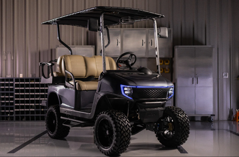
The Madjax Apex Body Kit for E-Z-GO RXV is a premium aftermarket upgrade designed to enhance both the aesthetics and functionality of your golf cart. The kit is priced at approximately $1,999.95. This comprehensive kit includes a stylish front cowl, rear body, and integrated lighting, providing a rugged yet modern look. Engineered for easy installation, the Apex Body Kit is compatible with both gas and electric models, making it a versatile choice for any golf cart enthusiast.
Specifications
The Madjax Apex Body Kit comes with several key features that make it an attractive upgrade for your E-Z-GO RXV:
- Durable Construction: Made from high-quality ABS plastic, ensuring durability and resistance to weather conditions.
- Ergonomic Design: Sleek and aerodynamic design that enhances the overall look of your golf cart.
- Easy Installation: Designed with user-friendly installation in mind, requiring minimal tools and technical expertise.
- Customizable: Available in various colors and can be customized to match your personal style.
- Compatibility: Specifically designed for the E-Z-GO RXV model, ensuring a perfect fit.
Description
The Madjax Apex Body Kit is more than just a cosmetic upgrade; it's a comprehensive solution that transforms the appearance and functionality of your E-Z-GO RXV. The kit includes a front cowl that provides improved protection from the elements, rear body panels that enhance the cart's rear profile, and other accessories like trim pieces and hardware.
The kit's ABS plastic construction ensures it is lightweight yet robust, capable of withstanding the rigors of regular use. The ergonomic design not only looks great but also improves airflow and reduces wind resistance, making your ride smoother and more comfortable.
ITEMS INCLUDED
Box 1
- Front Upper Grill
- Front Lower Grill
- Bag Well
- Access Cover
- Rear Bumper
- Horn
- LUX Light Module
- 48V to 12V DC Converter
Box 2
- Left and Right Front Fenders
- Left and Right Rear Fenders
- Headlight Set
- Taillight Set
- Center DRL
- Wire Harnesses (see page 2)
- Turn Signal Stalk and Covers
- Brake Switch
- Hardware Kit
- USB Outlet
- Hood Panel
- Kick Panel
TOOLS NEEDED
- Ratchet
- Drill
- Adjustable Wrench
- 10mm Socket
- 13mm Socket
- 15mm Socket
- 10mm Wrench
- 15mm Wrench
- 9/16" Insulated Wrench
- #2 Phillips Screwdriver
- 6mm Allen Wrench
- 1-1/8" Spade Drill Bit
- T20 Torx
- T25 Torx
- T27 Torx
- T45 Torx
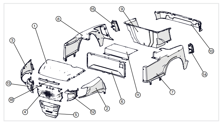
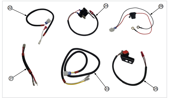
ITEM | PART NUMBER | ITEM NAME |
1 | 05-255-**** | CENTER HOOD, COWL,APEX,**** |
| 2 | 05-256-**** | FENDER,DRIVER SIDE, COWL,APEX,**** |
| 3 | 05-257-**** | FENDER,PASS SIDE, COWL, APEX,**** |
| 4 | 05-258-**** | UPPER GRILL, COWL,APEX,**** |
| 5 | 05-259-**** | LOWER GRILL, COWL, APEX,**** |
| 6 | 05-260-**** | FRONT PANEL, REAR BODY, APEX,**** |
| 7 | 05-261-**** | DRIVER SIDE PANEL,REAR BODY, APEX,**** |
| 8 | 05-262-**** | PASS SIDE PANEL, REAR BODY, APEX,**** |
| 9 | 05-263-BK02 | BAGWELL, REAR BODY,APEX, MATTE BLACK |
| 10 | 05-264-BK02 | BUMPER, REAR BODY,APEX, MATTE BLACK |
| 11 | 05-265-BK02 | ACCESS PANEL,REAR BODY,APEX,MATTE BLACK |
| 12 | 02-134-1 | HEADLIGHT, DRIVER SIDE,APEX, LUX |
| 13 | 02-134-2 | HEADLIGHT, PASS SIDE,APEX, LUX |
| 14 | 02-134-3 | TAIL LIGHT, DRIVERSIDE, APEX, LUX |
| 15 | 02-134-4 | TAIL LIGHT, PASSSIDE, APEX, LUX |
| 16 | 02-134-5 | WIREING HARNESS, APEX,LUX |
| 17 | 02-134-6 | RELAY, APEX, LUX |
| 18 | 02-134-7 | DRL, CETNER, APEX,LUX |
| 19 | 02-134 | APEX LUX LIGHT KIT |
| 20 | 05-269 | HARDWARE KIT, APEX |
| 21 | - - - | REVERSE BUZZER JUMPERHARNESS |
| 22 | - - - | GAS REVERSE LIGHTHARNESS |
| 23 | - - - | ELECTRIC REVERSE LIGHT HARNESS |
| 24 | - - - | GAS BRAKE SWITCH |
| 25 | - - - | ELECTRIC BRAKE SWITCH |
| 26 | - - - | MAIN POWER JUMPER HARNESS |
MadJax recommends professional installation. If you choose to not have this product installed by a professional, we highly recommend that you exercise cause, care, and patience when installing this product. The MadJax Limited Warranty only covers defects in materials and workmanship and does not cover damage due to improper installation. If you are having difficulty installing this product, contact your Authorized MadJax Dealer.
Be sure to read all instructions before starting installation.
!!ALL HARDWARE INTO PLASTIC BODY PANELS SHOULD BE HAND-TIGHTENED!!
Assembly Installation
VEHICLE PREPARATION
- For electric cars, battery removal is not required, but it is recommended that you disconnect all wires and cables from both the main positive and main negative battery terminals.
For gas cars, disconnect all cables from both the positive and negative battery terminals. Remove the motor cover, canopy, seat bottom, rocker panels, floor mounted horn button if applicable, floor mat, and rear seat kit if installed. Carefully note all hardware locations and retain all hardware.
The front strut can remain on the vehicle, but remove the rear struts.
NOTE: On most model years, there is access to remove the lower mounting bolts for the rear struts below the rear body. This will allow the rear strut assembly to be removed as one piece. Other model years do not have access to do this easily. If this is the case, remove the sweater basket, seat back, and upper rear struts individually and the lower rear struts can remain installed on the vehicle.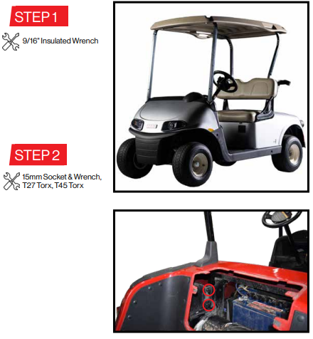
REAR BODY REMOVAL
ELECTRIC MODELS
Remove the charge port from the rear body, retaining the hardware.
Remove the clip nuts from the charge port hole in the RXV body. These will be installed onto the APEX body.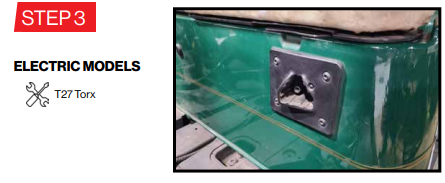
GAS MODELS
Remove and retain the FNR handle.
If applicable, disconnect the choke cable from the carburetor.
Remove the choke cable from the kick panel in one of three ways depending on the year of the vehicle.
Option 1: Remove the nut holding the back of the choke cable bracket onto the body and remove the choke cable from vehicle.
Option 2: Drill out the four rivets that hold the choke cable bracket to the body and remove the choke cable from the vehicle.
Option 3: Remove the four screws holding the choke cable bracket to the body and remove the choke cable from the vehicle. Remove the clip nuts from the RXV body.
If your vehicle has an EFI engine and does not have a choke cable, remove the close out plate that is over the choke cable hole on the RXV body. This will need to be installed into the Apex body.
In all model years, retain both the handle and choke cable along with all associated hardware.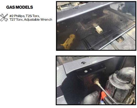
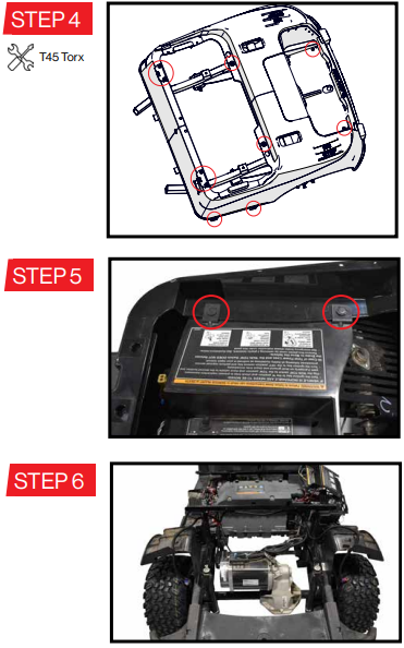
- Remove all screws holding the rear body to the vehicle:
- Four (4) screws on the sides (2 per side)
- Two (2) screws in the rear bag well
- Four (4) screws at the seat hinges
- Two (2) bolts at the rear of the front seat recess
Retain all hardware and both seat hinges.
- Unplug the taillights if equipped, and secure the stock harness to the vehicle and out of the way.
For electric vehicles, also remove the two rivets on the passenger's side of the battery compartment that hold the run/tow panel to the body. With a partner, carefully lift the rear body free from the vehicle.
FRONT COWL REMOVAL
- Remove two (2) nuts from the bottom of the cup holders.
Pull up and out on the top of the cup holders to free it from the instrument panel.
Unplug any USB or other electrical accessories installed into the cup holder.
Retain the cup holder and hardware. - Remove and retain the four (4) screws securing the front cowl to the instrument panel.
Unplug stock headlights if equipped and remove the front cowl.
Secure stock light harness out of the way using cable ties.
NOTE: If replacing an aftermarket light kit, remove the old light kit wiring harness.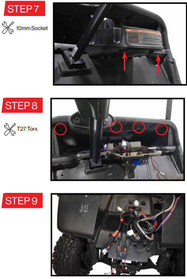
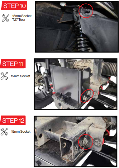
- Remove the two (2) upper nuts which secure the front bumper to the upper shock mounts. Do not remove the nut behind the bumper which is securing the shock to the frame.
Also remove one (1) screw securing the bottom of the bumper to the vehicle.
Remove the bumper from the vehicle. - Remove the lower bumper bracket by loosening the rear two (2) bolts and removing the front two (2) bolts.
Once the bumper bracket is off the vehicle, re-tighten the rear two (2) bolts. These will not be needed for the new body.
ELECTRICAL INSTALLATION
- Remove the pedal box cover by removing the rivets holding it to the floor.
Run the new wiring harness in the vehicle.
Then set the harness into the groove in the subfloor next to the stock vehicle harness and into the battery/engine compartment.
The harness will go around the battery/engine compartment on the driver's side.
The end with the large 12 pin connector and headlight connectors will be inserted through the access hole in the bottom of the cup holder area and set into the front dash.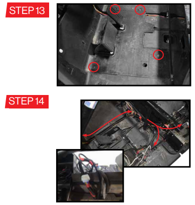
ELECTRIC vehicles: Steps 15-21
GAS vehicles: Steps 22-26Install the brake switch to the brake pedal frame by removing the two (2) highlighted rear bolts from the driver's side of the brake pedal frame.
Place the brake switch bracket in place as shown with the switch to the rear of the brake pedal .
Reinstall the two (2) bolts and cycle the brake pedal to ensure good engagement of the switch when the pedal is depressed. If needed, loosen the bolts and adjust the position of the switch. Then retighten the bolts.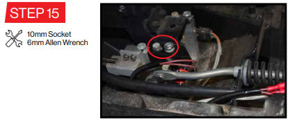
- On the wiring harness, locate the yellow and red wires with bullet connectors. Run these wires through the channel in the floorboard toward the brake switch.
Connect the two bullet connectors to the corresponding connectors from the brake switch.
Pull any slack toward the battery compartment.
Replace the pedal box cover and its associated rivets. - On the passenger's side of the vehicle, locate the reverse buzzer mounted to the bottom side of the run/tow panel.
Attach one t-lock connector to each of the wires coming from the reverse buzzer.
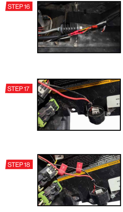
- Plug the reverse buzzer jumper harness into each of the t-locks. Plug the red wire of the harness into the t-lock on the red wire from the buzzer, and plug the black wire into the t-lock on the black wire.
- The electric reverse light harness with the yellow and white wires will plug into into the 2-pin connector on the light kit wiring harness that has a pink and a red wire.
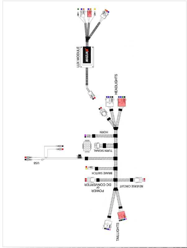
See harness images on Page 2 and main harness schematic on Page 27 for reference. Plug the blade connectors from both the reverse light harness and the reverse buzzer jumper harness into the relay as shown.
The red and black wires will plug into the two terminals that are in line with each other. The yellow and white wires will plug into the remaining two terminals
Tuck the relay in with the vehicle harness and secure as needed.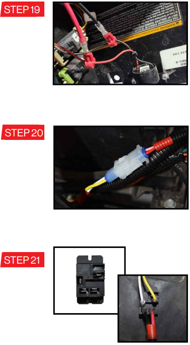
- Ensure the wheels are chocked and, if equipped, release the parking brake before installing the brake switch.
Removing the two (2) highlighted bolts from the driver's side of the brake pedal frame.
Place the brake switch bracket in place as shown and reinstall the two (2) bolts. Cycle the brake pedal to ensure good engagement of the switch when the pedal is depressed. If needed, loosen the bolts and adjust the position of the switch. Then retighten the bolts.
Re-engage the parking brake when complete. - On the wiring harness, locate the yellow and red wires with bullet connectors. Run these wires through the channel in the floorboard toward the brake switch.
Connect the two bullet connectors to the corresponding connectors of the brake switch.
Pull any slack toward the battery compartment.
Replace the pedal box cover and its associated rivets. Locate the reverse micro switch below the shifter lever.
Unplug one of the wires from its pole on the microswitch.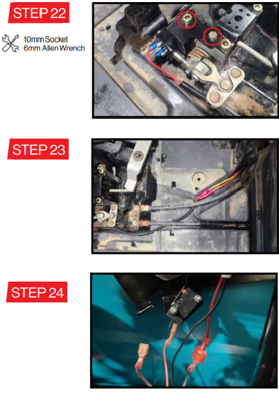
- Plug the female blade connector from the gas reverse light harness onto the pole of the micro switch.
Plug the wire removed in Step 24 onto the male blade connector of the gas reverse light harness. - Plug the gas reverse light harness into the Apex light kit harness.
Secure with cable ties as needed.
See harness images on Page 2 and main harness schematic on Page 27 for reference. Loosely install the turn signal stalk to the steering column.
This will be adjusted and secured later.
APEX BODY ASSEMBLY
!!ALL HARDWARE INTO PLASTIC BODY PANELS SHOULD BE HAND TIGHTENED!!
NOTE: Recommend assembling the body upside down on a work table. During assembly, use a work surface with a soft covering to avoid scratches to the body panels.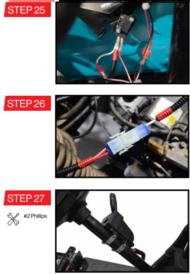
APEX BODY ASSEMBLY
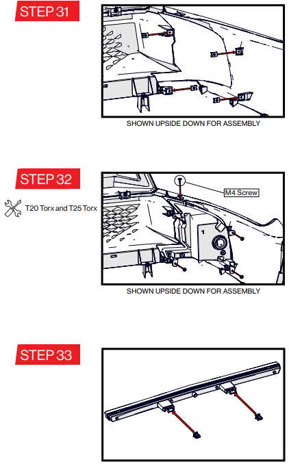
- Begin assembling the front cowl by installing the front fenders to the center hood panel using four (4) M4x12mm button head screws per fender.
As the hardware is being fully tightened, lightly press the panels together to minimize panel gaps. - Install three (3) threaded clips to the bosses on the center hood panel. The threaded part of the clip should be toward the top of the cowl assembly.
Assemble the upper grill to the center cowl using three (3) M5x15mm flat head screws. Install the lower grill to the upper grill using three (3) M4 screws.
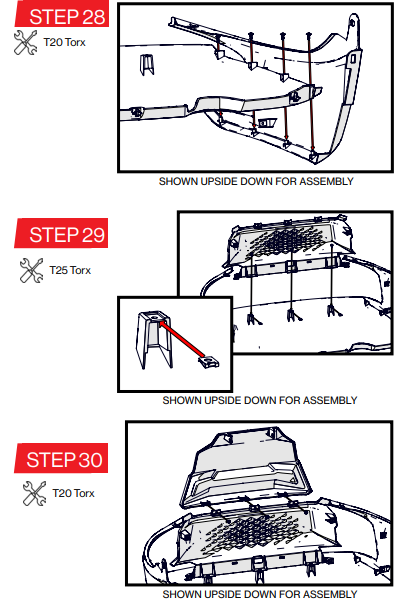
- Install four (4) threaded clips per side to the bosses shown for the headlights. The threaded part of the clip should be toward the front of the cowl assembly.
- Install each headlight using four (4) M5 screws into the threaded clips, and one (1) M4 screw into boss on the bottom of the headlight.
As the hardware is being fully tightened, press the panels together to minimize panel gaps.
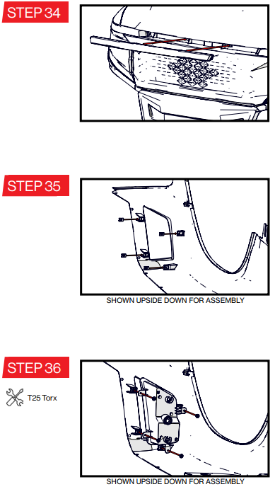
Carefully set the assembled front cowl to the side. Install two retaining clips to the rear tabs of the daytime running light.
- Feed the wires main connector from the DRL through the center hole of the upper grill. Feed the red wires around the gaps in the sides of the upper grill.
Press the DRL into place in the cowl. Be sure the retaining clips snap into place in the holes of the upper grill.
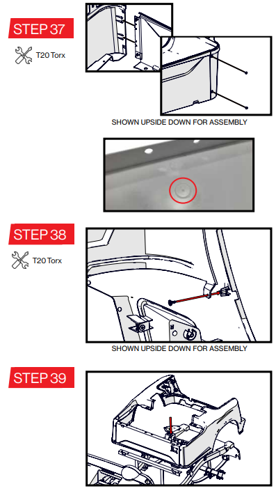
NOTE: The longer edge of the DRL will be on top. - Begin assembling the rear body by installing four (4) threaded clips per taillight onto each rear fender as shown. The threaded part of the clip should be toward the rear of the fender.
Install the taillights to the rear fender using four (4) M5 screws each.
- Install the rear fenders to the front kick panel using two (2) M4 screws per side, making sure the edge of the kick panel is engaged with the tabs on the back of the rear fender.
NOTE: Install the threaded clips previously removed from the stock kick panel onto the Apex kick panel around where the charge port or choke cable will go. If the vehicle did not have rivets or screws securing the choke cable, it will not need clips installed.
NOTE: If installing on a gas vehicle, use the guide ring on the interior side of the kick panel and
drill the selector hole (approximately 1") into the panel using a stepped or spade drill bit before assembling. - Install the rear bumper cover to the rear fenders using one (1) M4 screw per side.
With a partner, carefully flip the rear body over and set it onto the vehicle.
Ensure the tabs on the bottom side of the fenders are on the outside of the vehicle frame. The tabs on the bottom of the kick panel must be engaged with the corresponding slots in the floor board for the body to be fully seated in place.
- Install six (6) threaded clips per fender as shown. The threaded side of the clip should be to the underside of the body.
- Set bagwell in place.
Secure with twelve (12) M5 screws as shown.
As the hardware is being fully tightened, press the panels together to minimize panel gaps. Be sure the hole in the bagwell lines up with the screw bosses of the bumper. Secure the bagwell to the bumper using two (2) M4 screws.
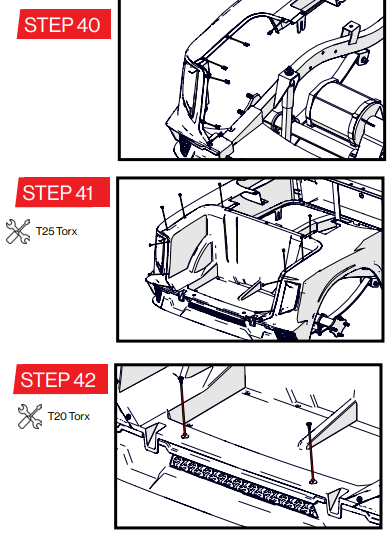
- Install seven (7) threaded clips along the top of the bagwell and side fenders.
The threaded side of the clip should be to the underside of the body.
NOTE: If installing a seat kit, now is a good time to install the seat kit brackets to the vehicle frame. - Set the access cover in place and secure with seven (7) M5 screws as shown.
Secure the front of the rear body by reinstalling the seat hinges using the stock hinge and hardware.
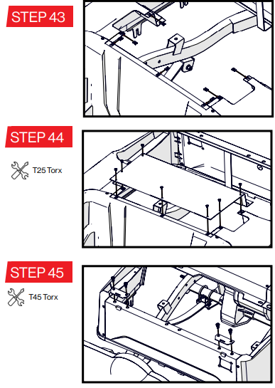
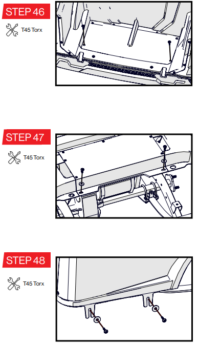
- Secure the bagwell to the rear of the vehicle frame using the hardware previously removed from the stock RXV bagwell.
NOTE: If installing a rear seat kit, add the seat kit bagwell brackets in this step. - Bolt the front of the access cover to the vehicle frame using the bolts and washers previously removed.
Bolt the sides of the body to the vehicle using the stock screws and washers (2 per side).
- GAS, reinstall the choke cable if applicable.
Option 1: Install the choke cable bracket into the kick panel. Hook the cable up to the carberator. Retighten the nut retaining the chock cable bracket to the kick panel.
Options 2&3: Install the choke cable bracket into the kick panel. Hook the cable up to the carberator. Install the choke cable bracket to the kick panel using the four (4) stock screws.
If the vehicle has an EFI engine, install the choke close out plate into choke cable hole in the kick panel.
Reinstall the shifter handle using the stock screw.
ELECTRIC, reinstall the charge port to the rear body. - Plug the taillights into the light kit harness.
The red connectors should plug together on the passenger's side, and the white connectors should plug together on the driver's side. At the front of the vehicle, find a suitable location for the horn and install it using one (1) M8x20mm bolt and one (1) M8 lock nut.
Plug the black and purple wires with blade connectors from the light kit harness onto the terminals of the horn.
NOTE: If the vehicle has a stock horn or from previous light kit, it can be removed from the vehicle.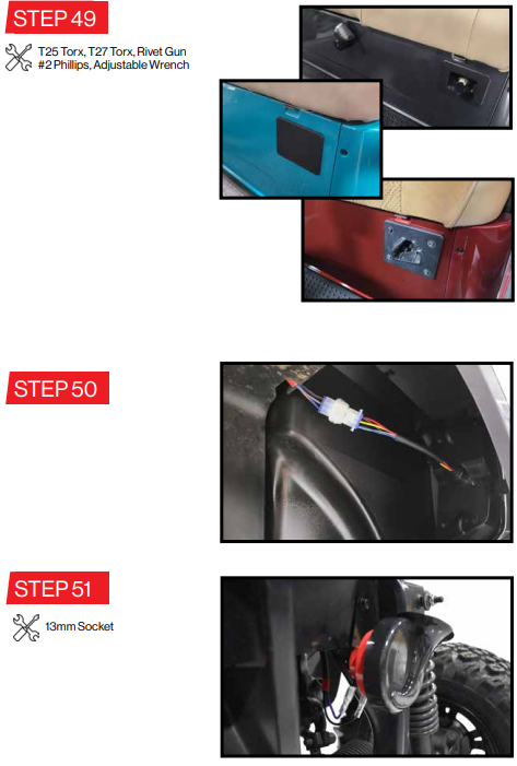
- Plug the LUX module into the light harness and set it on the wiring panel under the dash.
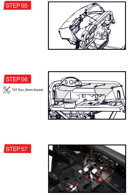
- Have a partner hold the front cowl in place while loosely installing the stock lower bolts where the stock bumper was installed.
With the cowl leaned forward, plug the headlights and day time running light into the light kit harness as shown.
Each headlight has a four pin and a two pin connector that each plug into the matching color connector
on the vehicle side. Red connectors are for the passenger's side. White connectors are for the driver's side. The four pin connectors are from the light kit harness, and the two pin connectors are from the LUX Module.
The DRL has a three pin connector that plugs into the corresponding three pin connector from the LUX Module
The red wires from the DRL will plug into the red wires coming from each headlight. The single wires from the headlights (yellow on the passenger side and green on the driver side) will be plugged into the corresponding colored bullet connectors coming from the LUX module.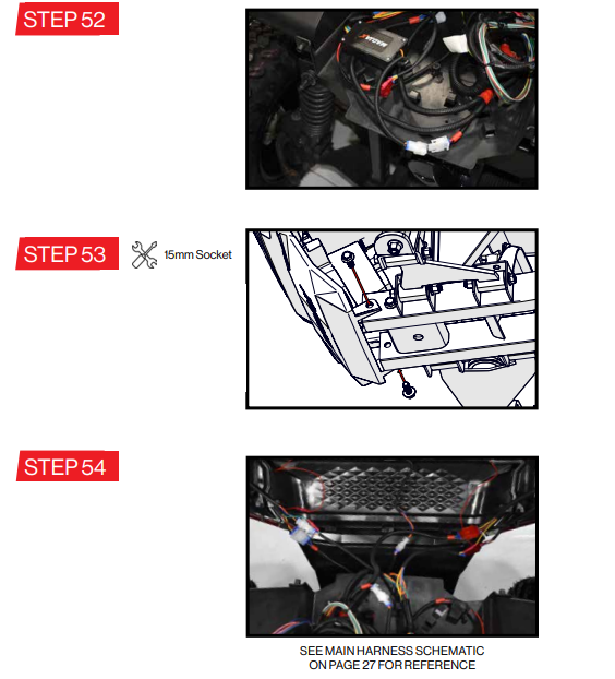
- Pivot the cowl upward into place under the dash trim panel.
Ensure the cowl is fully seated under the trim panel on both sides and along the top edge. - Apply gentle rearward pressure on the top of the cowl to help align the screw bosses on the cowl with the corresponding holes in the instrument panel.
Secure the cowl using the stock hardware.
Now tighten the lower bumper bolts. Pull any harness slack into the area behind the dash and secure as needed.
- Run the 12-pin and 3-pin connectors from the turn signal module in the dash down through the harness access hole in the bottom of the cup holder.
Bring the turn signal harness over to the module connectors and plug it in.
Also, plug the main connector from the light kit harness into the turn signal module. - Locate a place on the cup holder to install the USB port. Ensure there is enough space behind the selected area for the USB port to fit.
Drill a 1-1/8" hole into the panel or use the ring nut from the USB port as a template to cut the hole using a rotarty tool.
Install the USB port by tightening the plastic nut on the back of the panel.
Locate the fused red wire and the black wire in the light kit harnes and plug the blade connectors onto the back of the USB Port (red to positive and black to negative).
NOTE: The two extra red and black blade connections are for future electric accessories. Pull the turn signal stalk up the steering column and tighten the straps holding it to the column.
Install the plastic cover over the straps as well as the cover over the harness along the steering column.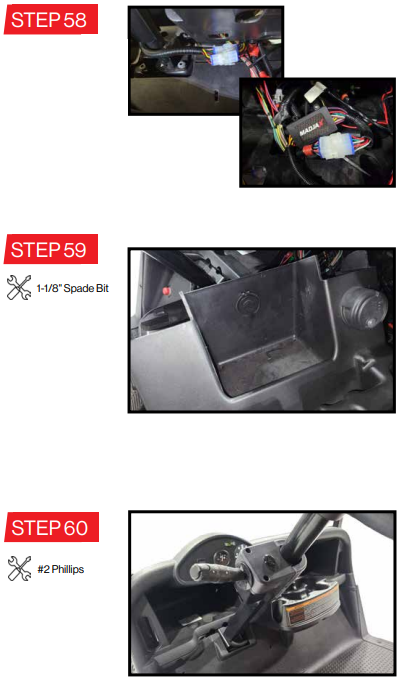
Next re-install the cup holder to the dash. Secure in place using the stock nuts.
ELECTRIC vehicles: Steps 62-63
GAS vehicles: Steps 64-65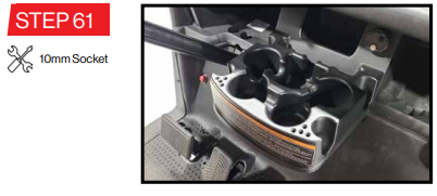
- For Lithium vehicles (shown), connect the ring terminal of the red wire in the main power jumper harness to the red (positive) power stud on the vehicle. Connect the ring terminal of the black wire in the mainpower jumper harness to the black (negative) power stud on the vehicle.
For lead acid vehicles (not shown), connect the ring terminal of the red wire in the main power jumper harness to the main positive battery terminal of the battery pack. Connect the ring terminal of the black wire in the power jumper harness to main negative battery terminal of the battery pack. The DC/DC Converter MUST be used for all electric vehicles.
Find a suitable location for the converter and secure using zip ties or screws (not included).
Plug the connector from the light kit harness into the yellow and black connector from the converter.
Plug the main power jumper harness into the red and black connector from the converter.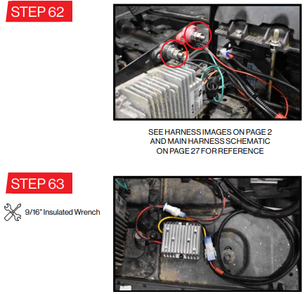
- Electric Vehicles skip to STEP 65.
Gas Vehicles:
Plug the main power jumper harness into the red and black connector on the main light kit harness. - Connect the ring terminal of the red wire in the main power jumper harness to the positive battery terminal. Connect the ring terminal of the black wire in the main power jumper harness to negative battery terminal.
Reconnect all other electrical connections to the battery that were previously removed in Step 1.
Tuck and secure all wires and harnesses as needed. Making sure no wires are hanging below the vehcile nor touching any moving or potential hot parts including the tires, exhaust, or other drive components.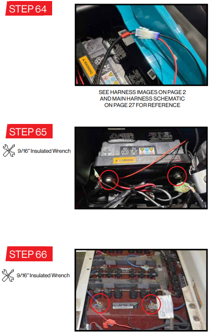
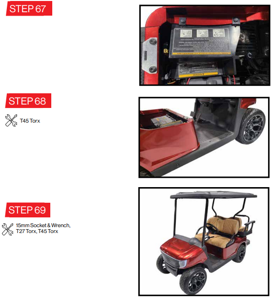
- Reinstall the Run/Tow panel to the rear body using the stock rivets.
- Place the floormat back in place, ensuring the harnesses are all in their appropriate grooves.
Reinstall the both rocker panels using the stock hardware. Reinstall any remaining parts previously removed in Steps 1 and 2.
Wiring Diagram
Setup Guide
To set up the Madjax Apex Body Kit, follow these steps:
- Prepare Your Cart: Ensure your E-Z-GO RXV is clean and free from any debris or old body panels.
- Unpack and Organize: Unpack all components of the kit and organize them according to the instruction manual.
- Install Front Cowl: Attach the front cowl using the provided hardware. Make sure it is securely fastened.
- Install Rear Body Panels: Align and attach the rear body panels, ensuring they are properly secured with the included fasteners.
- Add Trim and Accessories: Install any additional trim pieces and accessories according to the instructions.
Troubleshooting
If you encounter any issues during or after installation, here are some common problems and their solutions:
- Alignment Issues: Ensure all panels are properly aligned before securing them. If misaligned, adjust the panels and reattach.
- Loose Fasteners: Check all fasteners regularly to ensure they are tightened securely. Loose fasteners can lead to panel damage or detachment.
- Scratches or Cracks: Handle the panels with care during installation. If you notice any scratches or cracks, contact Madjax customer support for replacement parts.
Pros & Cons
Pros
- Durable Construction: High-quality materials ensure long-lasting performance.
- Elegant Design: Enhances the aesthetic appeal of your E-Z-GO RXV.
- Easy Installation: User-friendly design makes installation a breeze.
- Customization Options: Available in various colors and customizable to match your style.
Cons
- Cost: The kit is relatively expensive compared to other upgrade options.
- Time-Consuming Installation: While easy, installation may still require some time and effort.
- Compatibility Limitations: Specifically designed for E-Z-GO RXV models only.
Customer Reviews
Customers have generally praised the Madjax Apex Body Kit for its quality and ease of installation. Here are a few common reviews:
- "The Madjax Apex Body Kit has completely transformed my E-Z-GO RXV. The installation was straightforward, and the quality of the materials is top-notch." - John D.
- "I was a bit skeptical about spending so much on a body kit, but it's worth every penny. The design is sleek, and it's made my golf cart stand out on the course." - Sarah K.
However, some customers have noted that the price could be a barrier and that it takes some time to install all the components.
Faqs
What is the Madjax Apex Body Kit designed for?
What materials are used in the Madjax Apex Body Kit?
Is the Madjax Apex Body Kit E-Z-GO RXV easy to install?
Can I customize the Madjax Apex Body Kit?
What if I encounter alignment issues during installation?
How do I troubleshoot loose fasteners?
What if I notice scratches or cracks on the panels?
What do customers generally say about the Madjax Apex Body Kit E-Z-GO RXV?
Leave a Comment
