Makita Hole Puncher XPP01 Instruction Manual | Operations
Content
Introduction
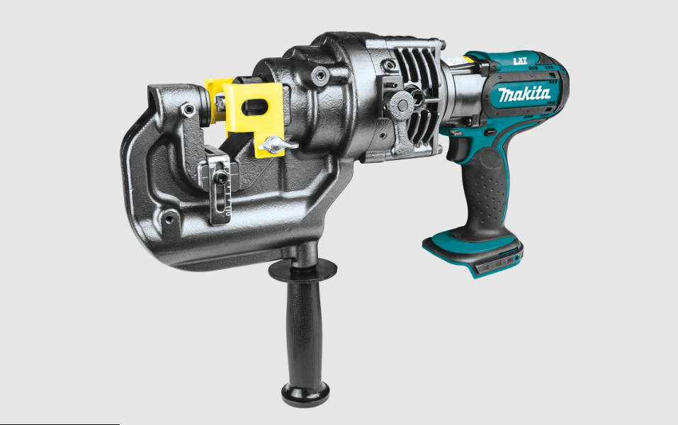
The Makita Hole Puncher XPP01 is a cutting-edge tool designed for efficient hole punching in metal, capable of creating up to 180 holes with a diameter of 25/32 inches in just seconds. Powered by an 18V LXT lithium-ion battery, it combines portability with high performance, making it ideal for various applications such as HVAC and plumbing. The cost of the XPP01 is approximately $399, reflecting its advanced features and capabilities.
Specifications
Model: | XPP01 | |
Max. throat depth | 40 mm (1-37/64″) | |
Shape of holes | Round / Oblong | |
Max. hole size and thickness | For mild steel of 65,000 psi tensile strength | Diameter : 20 mm (25/32″) Thickness : 8 mm (5/16″) |
For stainless steel of 89,000 psi tensile strength | Diameter : 20 mm (25/32″) Thickness : 6 mm (15/64″) | |
Rated voltage | D.C. 18 V | |
Dimensions (L x W x H) (with handle) | 417 mm x 127 mm x 315 mm (16-27/64″ x 5″ x 12-13/32″) | |
Net weight | 10.7 - 10.8 kg (23.6 - 23.8 lbs) | |
- Due to our continuing program of research and development, the specifications herein are subject to change without notice.
- Specifications may differ from country to country.
- Weight, with battery cartridge, according to EPTA-Procedure 01/2014
Applicable battery cartridge and charger
Battery cartridge | BL1830B / BL1840B / BL1850B / BL1860B |
Charger | DC18RC / DC18RD / DC18RE / DC18SD / DC18SE / DC18SF |
Some of the battery cartridges and chargers listed above may not be available depending on your region of residence.
WARNING: Only use the battery cartridges and chargers listed above. Use of any other battery cartridges and chargers may cause injury and/or fire.
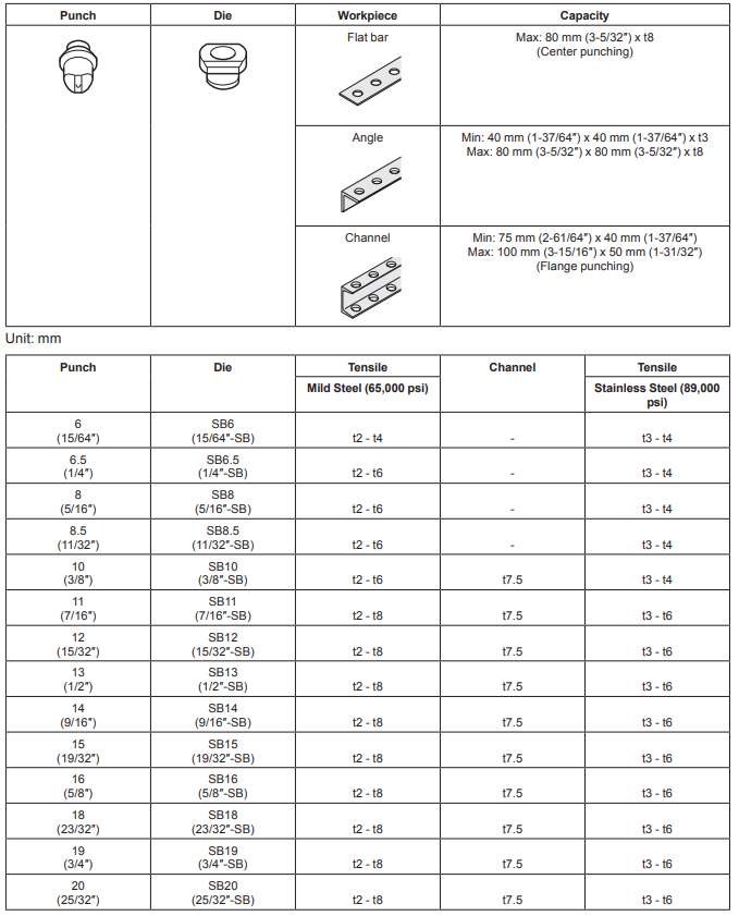
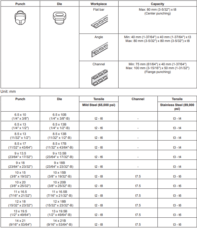
Combination of punch and die
Round punching
Oblong punching
Symbols
The followings show the symbols used for the equip-ment. Be sure that you understand their meaning before use.
 Read instruction manual.
 Flying debris and loud noise hazards. Wear ear and eye protection.
 Hazardous voltage. Disconnect all power before working on this equipment. Failure to observe this instruction may result in death or personal injury.
 Moving blade. Keep hands clear while machine is operating. Turn power off before servicing.
PARTS DESCRIPTION
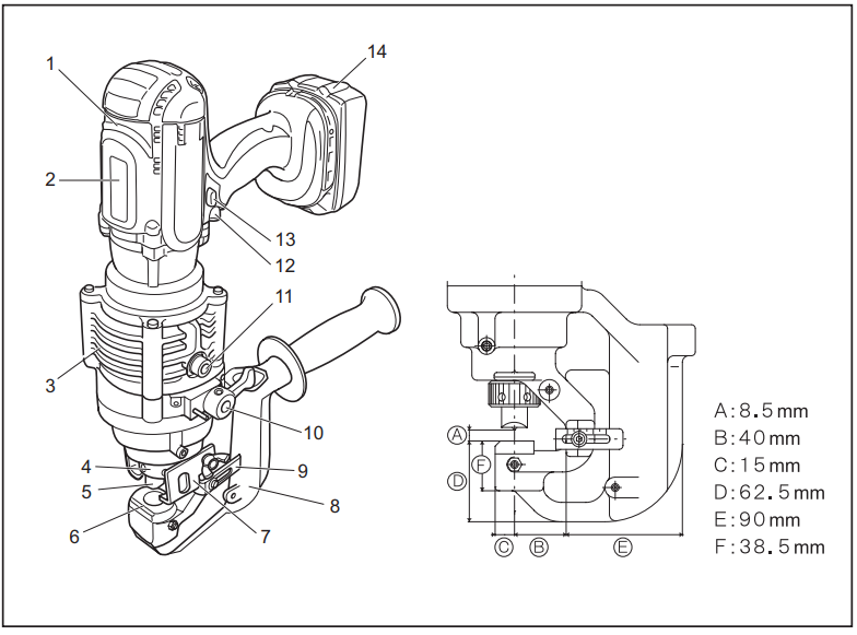
1 | Motor | 2 | Safety label | 3 | Pump case | 4 | Punch retaining nut |
5 | Punch | 6 | Die | 7 | Stripper | 8 | C frame |
9 | Slide stopper | 10 | Return lever | 11 | Oil port | 12 | Switch trigger |
13 | Trigger lock button | 14 | Battery cartridge | - | - | - | - |
FUNCTIONAL DESCRIPTION
CAUTION: Always be sure that the tool is switched off and the battery cartridge is removed before adjusting or checking function on the tool.
Installing or removing battery cartridge
CAUTION: Always switch off the tool before installing or removing of the battery cartridge.
CAUTION: Hold the tool and the battery car-tridge firmly when installing or removing battery cartridge. Failure to hold the tool and the battery cartridge firmly may cause them to slip off your hands and result in damage to the tool and battery cartridge and a personal injury.
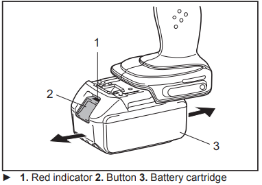
To remove the battery cartridge, slide it from the tool while sliding the button on the front of the cartridge.
To install the battery cartridge, align the tongue on the battery cartridge with the groove in the housing and slip it into place. Insert it all the way until it locks in place with a little click. If you can see the red indicator on the upper side of the button, it is not locked completely.
CAUTION: Always install the battery cartridge fully until the red indicator cannot be seen. If not, it may accidentally fall out of the tool, causing injury to you or someone around you.
CAUTION: Do not install the battery cartridge forcibly. If the cartridge does not slide in easily, it is not being inserted correctly.
Battery protection system
The tool is equipped with a battery protection system. This system automatically cuts off power to the motor to extend tool and battery life. The tool will automatically stop during operation if the tool or battery is placed under the following condition.
Over-discharge protection
When the battery capacity is not enough, the tool stops automatically. In this case, remove the battery from the tool and charge the battery.
Indicating the remaining battery capacity
Only for battery cartridges with the indicator
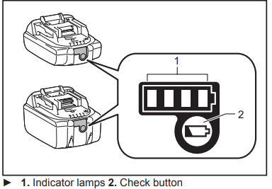
Press the check button on the battery cartridge to indi-cate the remaining battery capacity. The indicator lamps light up for a few seconds.
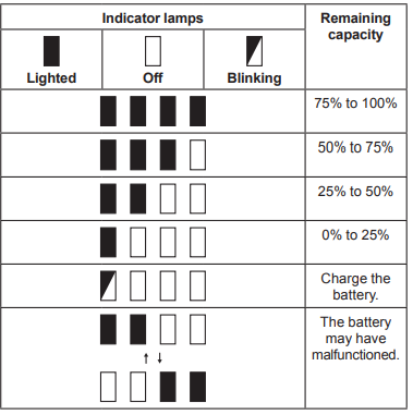
NOTE: Depending on the conditions of use and the ambient temperature, the indication may differ slightly from the actual capacity.
Switch action
CAUTION: Before installing the battery car-tridge into the tool, always check to see that the switch trigger actuates properly and returns to the "OFF" position when released.
CAUTION: Always lock the switch trigger when not in use.
When punching a workpiece, continue to pull the switch trigger until the punch goes down to the die and returns to the start position.
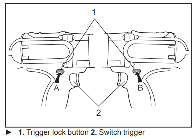
To lock the switch trigger, push in the trigger lock button from B side. To unlock, push in the trigger lock button from A side
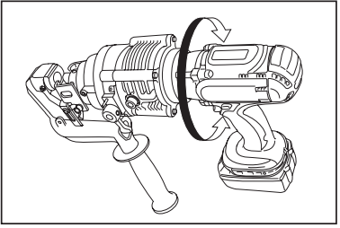
Rotatable grip
The grip can be rotated though 360 degrees, in either direction, during operation. This feature is particularly useful when working in awkward or narrow areas as it allows the operator to position the tool in the best posi-tion for easy operation.
ASSEMBLY
CAUTION: Always be sure that the tool is switched off and the battery cartridge is removed before carrying out any work on the tool.
Replacing the punch and die
Replacing round punch
Be sure that the punch piston is fully retracted and remove the strippers to make access to the parts easier.
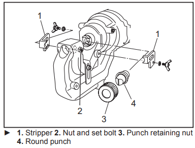
- The punch must be removed first and then the die. Unscrew the punch retaining nut to remove the punch and remove the set bolt and the nut to remove the die.
NOTICE: When replacing the punch and the die, make sure that the correct size, thickness and hole shape is selected. Shaped punches and dies must be properly aligned with each other. - Place the die in the C frame in the proper orienta-tion. Secure firmly with the set bolt and tighten the nut.
- Place the punch in the punch retaining nut. Insert the punch with the nut into the punch piston and hand tighten the nut.
NOTICE: When installing a punch with a stepped edge (anti rotation), make sure the orientation is correct and that the stepped edge is correctly positioned in the punch piston. Make sure the punch is correctly positioned in the punch rod and tighten the punch retaining nut firmly with the nut retaining bar supplied.
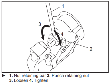
- Restore the strippers.
WARNING: If the punch and die are not the same size or the punch and the die are not positioned properly, the punch may strike the die causing both parts to break. In such a case, pieces flying off from the broken parts may cause personal injury.
CAUTION: Check the butterfly bolts which hold the stripper regularly to ensure that they are tight. Loose bolts may cause the stripper to come off and damage the tool.
Replacing oblong punch
Be sure that the punch piston is fully retracted and remove the strippers to make access to the parts easier.
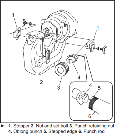
- The punch must be removed first and then the die. Unscrew the punch retaining nut to remove the punch and remove the set bolt and the nut to remove the die.
NOTICE: When replacing the punch and the die, make sure that the correct size, thickness and hole shape is selected. Shaped punches and dies must be properly aligned with each other. - Secure the oblong die firmly with the set bolt and tighten the nut.
- Place the oblong punch into the punch retaining nut. Position the stepped edge of the oblong punch properly in the punch piston and hand tighten the punch retaining nut.
NOTICE: If the stepped edge of the oblong punch is not properly inserted into the punch piston, the punch retaining nut cannot be fas-tened. Make sure the oblong punch is positioned correctly in the punch rod. Push the oblong punch against the punch rod and tighten the punch retaining nut firmly with the nut firmly with the nut retaining bar supplied.
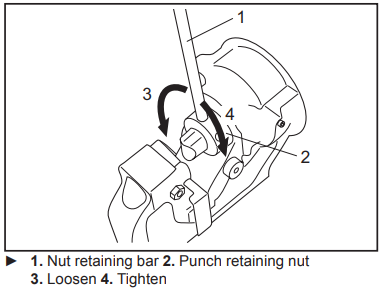
- Restore the strippers.
WARNING: If the punch and die are not the same size or the punch and the die are not positioned properly, the punch may strike the die causing both parts to break. In such a case, pieces flying off from the broken parts may cause personal injury.
CAUTION: Check the butterfly bolts which hold the stripper regularly to ensure that they are tight. Loose bolts may cause the stripper to come off and damage the tool.
CAUTION: Make sure the stepped edge of the oblong punch is positioned correctly in the punch rod and the punch retaining nut is properly fastened.
OPERATION
Correct use of the tool
Die selection
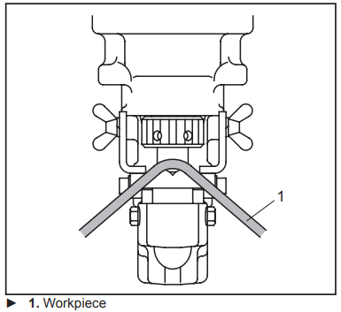
It is important that the die to be used is correct for the thickness of the workpiece to be punched. Punching the workpiece of 4 mm (5/32″) to 8 mm (5/16″) thickness using a die for thinner workpiece can cause the punch to jam in the workpiece. This is due to the smaller clear-ance between the die and punch. In such a case, the workpiece will be pulled up by the retracting punch as shown in the figure. Special care should be taken when punching flat bar of mild steel, aluminum and copper.
Correct use of the stripper
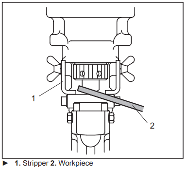
Do not position the workpiece with one end or both ends unsupported by the stripper. If the workpiece is not properly supported, it will move when the punch returns. It may cause the punch to jam and damaging the tool.
Punching a hole
CAUTION: Before punching, always make sure that the proper punch and die are installed correctly.
Check the position for punching.
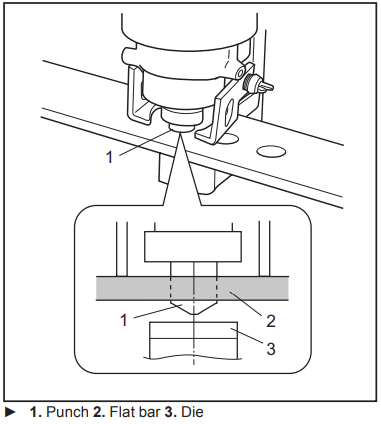
- Loosen the cap screw on the slide stopper and adjust the slide stopper to the desired position. After that, retighten the cap screw.
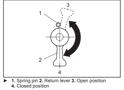
NOTE: The slide stopper is set to hold the hole puncher at a constant distance from the edge of the work piece. Check that the return lever is fully closed in the clockwise direction.
- Check that the punch piston is fully retracted.
- Place the puncher in the required position on the workpiece using the slide stopper as a guide. Align the point of the punch with the center mark of the hole to be punched.
- Continue to pull the switch trigger until the punch reaches the end of its stroke and returns to the starting position.
The punch rod will extend and push the punch through the workpiece.
NOTE: To aid accurate and easy positioning of the punch, pull the switch trigger intermittently to jog the punch down to the workpiece. If the position is not satisfactory, open the return lever to retract the punch for another attempt. If the punch doesn’t return to its starting position with return lever open, pull the switch trigger to return the punch.
NOTE: If the punch doesn’t return after punching finishes, release the switch trigger to stop the motor and pull the switch trigger again. If the punch doesn’t return even after performing above procedures, perform the procedures for stopping the oper-ation before the completion of punching mentioned below.
Stopping the operation before the punching is finished
If you want to stop the operation before the punching is finished, perform the procedures below:
- Turn the return lever counterclockwise until it hits the spring pin and then immediately back to its starting position.
Doing this releases the internal pressure of the tool. If the punch retracts from the workpiece under its own power, allow the punch to fully return. After that, turn the return lever back to its starting position. In this case, the following step is not necessary. - Continue to pull the switch trigger until the punch returns to its starting position.
Using slide stopper for maximum depth
Optional accessory
CAUTION: Before attaching or removing the slide stopper, ensure that the battery cartridge is removed to prevent accidental operation and personal injury.
Punching up to 40 mm (1-37/64″) depth from the edge of the workpiece can be done using the optional slide stopper.
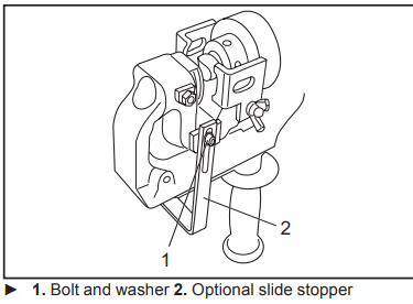
- Loosen the set bolt and nut to remove the die.
- Remove the bolt and washer fixing the slide stopper.
- Remove the slide stopper by pulling it to the upper side of the C frame.
- Insert the optional slide stopper for maximum depth from the bottom side of the C frame.
- Fix the optional slide stopper with the bolt and washer removed in step 2.
- Install the die with the set bolt and nut removed in step 1.
Setup Guide
Setting up and operating the Makita Hole Puncher XPP01 is straightforward:
- Insert the 18V LXT Lithium-Ion battery into the tool.
- Select your desired drill bit or punch attachment.
- Adjust the depth stop according to your project requirements.
- Hold the tool firmly with both hands and engage it by pulling the trigger.
- Use variable speed control as needed to achieve optimal results.
MAINTENANCE
CAUTION: Always be sure that the tool is switched off and the battery cartridge is removed before attempting to perform inspection or maintenance.
NOTICE: Never use gasoline, benzine, thinner, alcohol or the like. Discoloration, deformation or cracks may result.
To maintain product SAFETY and RELIABILITY, repairs, any other maintenance or adjustment should be performed by Makita Authorized or Factory Service Centers, always using Makita replacement parts.
Regular maintenance
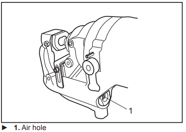
Keep the air hole at the end of the C frame clear of dirt and obstructions. The air hole has to be open in order to control the hydraulic pressure.
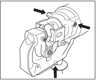
Do not undo or remove the three screws as shown in the figure. Doing so will cause oil to leak from the tool.
Addling oil in Makita Hole Puncher XPP01
This tool is electro-hydraulic. When shipped from the factory, it was filled with the oil. Do not attempt to add oil as long as the tool performs well. When the oil-pressure is not enough for proper operation, add oil in the follow-ing procedures.
NOTICE: Make sure that the work area and all equipment is clean so that no dirt, dust or other foreign materials can get into the hydraulic oil or pump area.
NOTICE: Only use pure hydraulic oil recom-mended by Makita. To prevent damage to the seals and other internal machine parts, do not use other oil listed below.
Recommended oil:
- Makita hydraulic oil
- Super Hyrando #46 (JXTG Nippon Oil & Energy Corp.)
- Shell Tellus Plus #46 (U.S. Shell)
- Hydraulic oil with equivalent spec anti-wear, ISO Viscosity Grade 46.
- Install the battery cartridge to the tool.
- Lay the tool on its left side so that the oil port is facing up.
- Operate the tool to move the punch position almost to the bottom of its stroke.
NOTE: If necessary, run the tool for several strokes. Doing so allows you to determine the bottom of stroke and also position the punch piston correctly. In the correct position, the maximum amount of oil has been drawn from the pump and the appropriate amount of oil for refill can be obtained. Remove the battery cartridge from the tool.
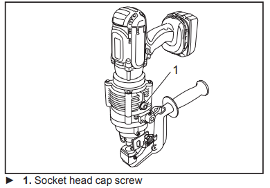
- Carefully remove the socket head cap screw to open the oil port.
- Fill the reservoir with hydraulic oil using the small squeeze bottle which is supplied with the tool.
- Rock the tool back and forth slightly several times to free any trapped air bubbles. After that, add addi-tional oil as necessary.
- Replace the socket head cap screw and wipe up any excess oil.
- Install the battery cartridge and run the tool for several strokes with the return lever is in open position. After that, run the tool again with the return lever is in closed position.
Doing this purges trapped air out of the system. Repeat this procedure to make sure that the punch piston is almost at the bottom of its stroke.
- Install the battery cartridge and run the tool for several strokes with the return lever is in open position. After that, run the tool again with the return lever is in closed position.
- Add additional oil as necessary by repeating step 3 to 9.
If the oil is depleted excessively, you need to repeat this procedure several times.
Replacing carbon brushes
Replace the carbon brushes when they wear down to the limit mark.
NOTICE: Keep the carbon brushes clean and free to slip in the holders.
NOTICE: Both carbon brushes must be replaced at the same time.
NOTICE: Use only identical carbon brushes.
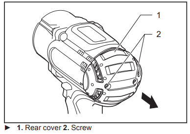
Remove two screws on the rear cover using a screwdriver and then remove the rear cover.
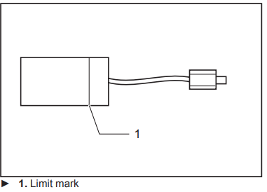
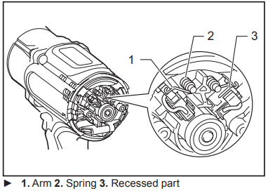
Raise the arm part of the spring and then place it in the recessed part of the housing with a slotted bit screwdriver or the like.
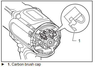
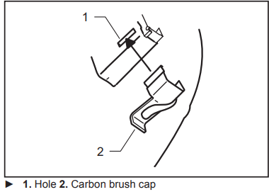
Remove the carbon brush caps of the carbon brushes using pliers and then take out the worn carbon brushes. Insert the new carbon brushes and attach the carbon brush caps.
Make sure that the carbon brush caps have fit into the holes in brush holders securely.
Reinstall the rear cover and tighten two screws securely.
Troubleshooting
Before asking for repairs, conduct your own inspection first. If you find a problem that is not explained in the manual, do not attempt to dismantle the tool. Instead, ask Makita Authorized Service Centers, always using Makita replace-ment parts for repairs.
State of abnormality | Probable cause (malfunction) | Remedy |
Punch piston will not come out. | Oil is insufficient | Refill oil. |
Punch piston has not returned com- pletely due to rebar chips, iron powder and dirt in the sliding portion of punch piston and C frame. | Push back punch piston. Clean punch piston. | |
Punch piston has not returned com- pletely due to the distortion or swelling of punch piston. | Ask your local authorized service center for repair. | |
Punch piston has not returned com- pletely due to weak return spring. | Ask your local authorized service center for repair. | |
Although punch piston comes out, cutting power is too weak to hole punching. | Oil is insufficient. | Refill oil. |
Contact between cylinder and release valve is improper. There may be scratches at chimney of cylinder or iron powder or dirt are sticking there. | Ask your local authorized service center for repair. | |
Breakage of release valve. | Ask your local authorized service center for repair. | |
Improper clearance between cylinder and piston. | Ask your local authorized service center for repair. | |
Improper contact between cylinder and check valve. | Ask your local authorized service center for repair. | |
Breakage of urethane packing of cylinder. | Ask your local authorized service center for repair. | |
Oil leaks. | Scratches on or breakage of oil leveler sack. | Ask your local authorized service center for repair. |
Scratches at sliding portion of C frame and punch piston and at back-up ring. | Ask your local authorized service center for repair. | |
Breakage of O-ring at joint of C frame and cylinder. | Ask your local authorized service center for repair. | |
Breakage of liner at joint of cylinder and pump case. | Ask your local authorized service center for repair. | |
Insufficient tightening of bolts at respec- tive parts. | Tighten bolts. | |
Motor does not move. Poor motor rotation. | Insufficient charge of battery cartridge. | Charge battery cartridge. |
Battery life cycle worn off. | Replace battery cartridge. | |
Breakage of motor by overheating. | Ask your local authorized service center for repair. | |
Deformation or breakage of bearings and gear connected to the motor. | Ask your local authorized service center for repair. |
CAUTION: The internal components of the pump have very close clearances and are sensitive to damage from dust, dirt, contamination of the hydraulic fluid or improper handling. The disassembly of the pump housing requires special tools and training, and should only be attempted by repair personnel who have been properly trained and have the proper equipment. The improper servicing of electrical compo-nents can lead to conditions that could cause serious injury. The pump and piston components and all electrical components should be serviced only by authorized repair shop, dealer or distributor.
NOTICE: Any attempt by unauthorized personnel to service the internal components of the pump area will void the warranty.
OPTIONAL ACCESSORIES
CAUTION: These accessories or attachments are recommended for use with your Makita tool specified in this manual. The use of any other accessories or attachments might present a risk of injury to persons. Only use accessory or attachment for its stated purpose.
If you need any assistance for more details regard-ing these accessories, ask your local Makita Service Center.
- Work stand
- Slide stopper (Max. throat depth)
- Makita genuine battery and charger
NOTE: Some items in the list may be included in the tool package as standard accessories. They may differ from country to country.
Makita Hole Puncher XPP01 Pros & Cons
Pros
- Powerful Performance: Consistently delivers strong punching power.
- Ergonomic Design: Reduces fatigue during extended use.
- Adjustable Settings: Allows for precise control over hole depth and speed.
- Durable Construction: Built to last with high-quality materials.
- LED Light Illumination: Enhances visibility in low-light conditions.
Cons
- Battery Life Concerns: Some users report shorter battery life under heavy use.
- Noisy Operation: Can be loud during operation, requiring ear protection.
- Additional Costs for Accessories: May require additional investment in drill bits or punches.
Customer Reviews
Customers have praised the Makita Hole Puncher XPP01 for its reliability and ease of use. Many have noted its ability to punch through tough materials effortlessly, making it an invaluable addition to their toolkits. However, some users have reported minor issues with battery life and noise levels during operation.
Faqs
What is the recommended usage for the Makita Hole Puncher?
How do I maintain the Makita Hole Puncher to ensure longevity?
What safety precautions should I take when using the Makita?
How do I adjust the depth stop on the Makita Hole Puncher?
Is there an LED light on this model? If so, how does it help?
Can I purchase additional accessories like drill bits separately?
What kind of materials can I punch through using this tool?
How do I troubleshoot if my tool isn't turning on?
Is there any warranty available for this product?
Leave a Comment
