Msi Motherboard H110M Pro VD-Plus Complete Guide
Content
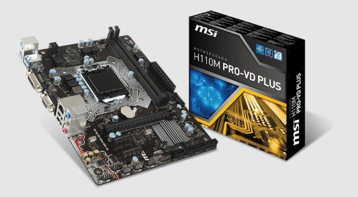
Introduction of MSI Motheboard H110M Pro VD-Plus
The MSI H110M Pro VD-Plus is a budget-friendly motherboard that supports Intel 6th and 7th Gen processors. This motherboard is perfect for building a small form factor gaming PC or a home theater PC. With a price point below $60, it's an excellent choice for those on a tight budget. The motherboard was launched in May 2017 and has been a popular choice among budget-conscious consumers ever since.
Specifications
CPU
Supports 6th Gen Intel Core i3/i5/i7 processors, and Intel Pentium and Celeron processors for Socket LGA1151
Chipset
Intel H110 Chipset
Memory
2x DDR4 memory slots, support up to 32GB
Supports DDR4 2133 MHz
Dual channel memory architecture
Supports non-ECC, un-buffered memory
Supports Intel Extreme Memory Profile (XMP)
Expansion Slots
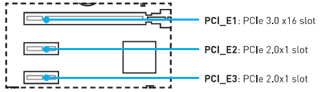
1x PCIe 3.0 x16 slot
2x PCIe 2.0 x1 slots
Onboard Graphics
H110M PRO-VH PLUS
1x VGA port, supports a maximum resolution of 2048x1536@50Hz, 2048x1280@60Hz, 1920x1200@60Hz
1x HDMI™ port, supports a maximum resolution of 4096x2160@24Hz, 2560x1600@60Hz
H110M PRO-VD PLUS
1x VGA port, supports a maximum resolution of 2048x1536@50Hz, 2048x1280@60Hz, 1920x1200@60Hz
1x DVI-D port, supports a maximum resolution of 1920x1200@60Hz
Storage
Intel H110 Chipset
4x SATA 6Gb/s ports
USB
Intel H110 Chipset
4x USB 3.1 Gen1 (SuperSpeed USB) ports (2 ports on the back panel, 2 ports available through the internal USB connector)
6x USB 2.0 (High-speed USB) ports (2 ports on the back panel, 4 ports available through the internal USB connectors)
Audio
Realtek ALC887 Codec
7.1-Channel High Definition Audio*
The HD audio module in the front panel of the chassis is needed to support a 7.1-channel audio output.
LAN
1x Realtek® RTL8111H Gigabit LAN controller
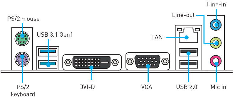
Back Panel Connectors
1x PS/2 mouse port
1x PS/2 keyboard port
2x USB 3.1 Gen1 ports
1x HDMI port (H110M PRO-VH PLUS)
1x DVI-D port (H110M PRO-VD PLUS)
1x VGA port
1x LAN (RJ45) port
2x USB 2.0 ports
3x audio jacks
Internal Connectors
1x 24-pin ATX main power connector
1x 4-pin ATX 12V power connector
4x SATA 6Gb/s connectors
2x USB 2.0 connectors (supports additional 4 USB 2.0 ports)
1x USB 3.1 Gen1 connector (supports additional 2 USB 3.1 Gen1 ports)
1x 4-pin CPU fan connector
1x 4-pin system fan connector
1x Front panel audio connector
2x Front panel connectors
1x TPM module connector
1x Serial port connector
1x Chassis Intrusion connector
1x Clear CMOS jumper
I/O Controller
NUVOTON NCT55363D Controller Chip
Hardware Monitor
CPU/System temperature detection
CPU/System fan speed detection
CPU/System fan speed control
Form Factor
Micro-ATX Form Factor
8.9 in. x 6.6 in. (22.6 cm x 17.3 cm)
BIOS Features
1x 64 Mb flash
UEFI AMI BIOS
ACPI 5.0, PnP 1.0a, SM BIOS 2.8
Multi-language
Software
Drivers
COMMAND CENTER
LIVE UPDATE 6
FAST BOOT
SUPER CHARGER
M-CLOUD
RAMDISK
Intel Small Business Basics
NETWORK GENIE
Intel Extreme Tuning Utility
Norton™ Security
Google Chrome, Google Toolbar, Google Drive
CPU-Z
MYSTIC LIGHT
MSI Exclusive Features
CLICK BIOS
COMMAND CENTER
RAMDISK
SUPER CHARGER
FAST BOOT
LIVE UPDATE 6
M-CLOUD
MYSTIC LIGHT
Overview of Components
Rear I/O Panel
H110M PRO-VH PLUS
H110M PRO-VD PLUS
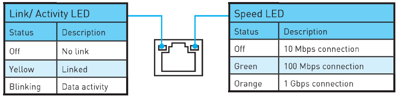
LAN Port LED Status Table
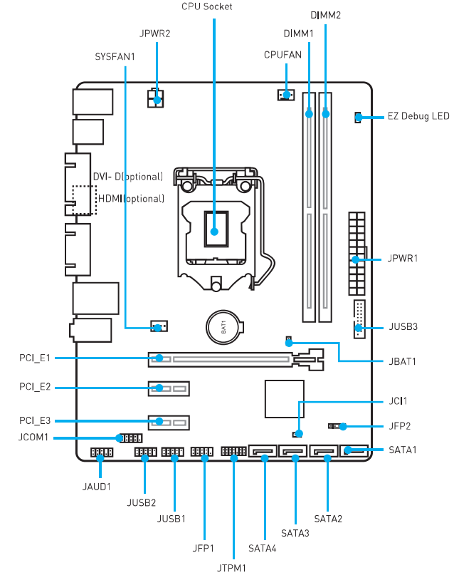
CPU Socket
Please install the CPU into the CPU socket as shown below.
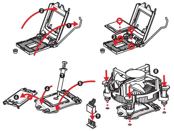
Always unplug the power cord from the power outlet before installing or removing the CPU.
Please retain the CPU protective cap after installing the processor. MSI will deal with Return Merchandise Authorization (RMA) requests if only the motherboard comes with the protective cap on the CPU socket.
When installing a CPU, always remember to install a CPU heatsink. A CPU heatsink is necessary to prevent overheating and maintain system stability.
Confirm that the CPU heatsink has formed a tight seal with the CPU before booting your system.
Overheating can seriously damage the CPU and motherboard. Always make sure the cooling fans work properly to protect the CPU from overheating. Be sure to apply an even layer of thermal paste (or thermal tape) between the CPU and the heatsink to enhance heat dissipation.
Whenever the CPU is not installed, always protect the CPU socket pins by covering the socket with the plastic cap.
If you purchased a separate CPU and heatsink/cooler, please refer to the documentation in the heatsink/cooler package for more details about installation.
DIMM Slots
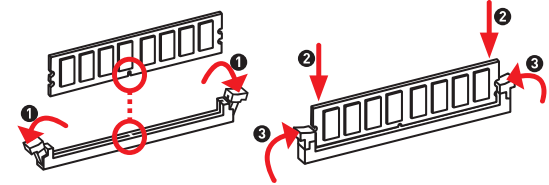
Please install the memory module into the DIMM slot as shown below.
Important
Due to chipset resource usage, the available capacity of memory will be a little less than the amount installed.
Please note that the maximum capacity of addressable memory is 4GB or less for 32-bit Windows OS due to memory address limitation. Therefore, we recommend that you install 64-bit Windows OS if you want to install more than 4GB memory on the motherboard.
PCI_E1-3: PCIe Expansion Slots
When adding or removing expansion cards, always turn off the power supply and unplug the power supply power cable from the power outlet. Read the expansion card's documentation to check for any necessary additional hardware or software changes.
SATA1-4: SATA 6Gb/s Connectors
These connectors are SATA 6Gb/s interface ports. Each connector can connect to one SATA device.
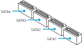
Please do not fold the SATA cable at a 90-degree angle. Data loss may result during transmission otherwise.
SATA cable has identical plugs on either side of the cable. However, it is recommended that the flat connector be connected to the motherboard for space-saving purposes.
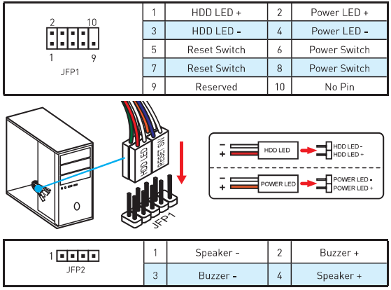
JFP1, JFP2: Front Panel Connectors
These connectors connect to the switches and LEDs on the front panel.
JPWR1-2: Power Connectors
These connectors allow you to connect an ATX power supply.
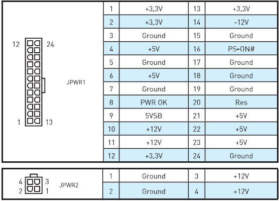
Important: Make sure that all the power cables are securely connected to a proper ATX power supply to ensure stable operation of the motherboard.
JUSB1-2: USB 2.0 Connectors
These connectors allow you to connect USB 2.0 ports on the front panel.
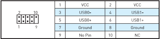
Note that the VCC and Ground pins must be connected correctly to avoid possible damage.
In order to recharge your iPad, iPhone, and iPod through USB ports, please install MSI® SUPER CHARGER utility.
JUSB3: USB 3.1 Gen1 Connector
This connector allows you to connect USB 3.1 Gen1 ports on the front panel.
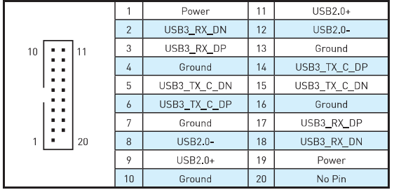
Important: Note that the Power and Ground pins must be connected correctly to avoid possible damage.
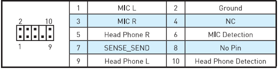
JAUD1: Front Audio Connector
This connector allows you to connect audio jacks on the front panel.
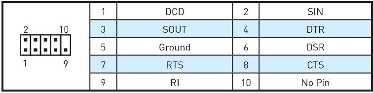
JCOM1: Serial Port Connector
This connector allows you to connect the optional serial port with a bracket.
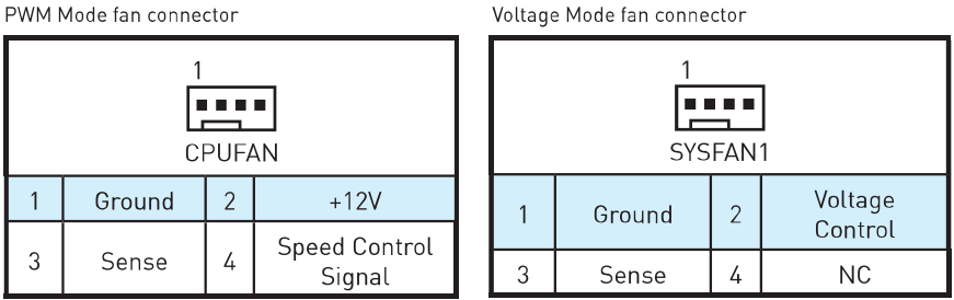
CPUFAN, SYSFAN1: Fan Connectors
Fan connectors can be classified as PWM (Pulse Width Modulation) Mode and Voltage Mode. PWM Mode fan connectors provide constant 12V output and adjust fan speed with a speed control signal. Voltage Mode fan connectors control fan speed by changing voltage. Therefore, when you plug a 3-pin (Non-PWM) fan into a PWM Mode fan connector, the fan speed will always be maintained at 100%, and that could be noisy.
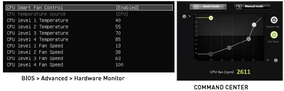
Controlling the fan speed
There are two ways to manage fan speed. One is to go to BIOS> Advanced> Hardware Monitor. The other is to use the COMMAND CENTER application.
BIOS Hardware Monitor sub-menu allows you to set the temperature levels and the corresponding fan speed levels.
COMMAND CENTER offers gradient points of the fan speed that allow you to adjust fan speed in relation to CPU temperature.
JTPM1: TPM Module Connector
This connector is for TPM (Trusted Platform Module). Please refer to the TPM security platform manual for more details and usages.
JCI1: Chassis Intrusion Connector
This connector allows you to connect the chassis intrusion switch cable.
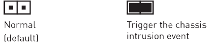
Using chassis intrusion detector
Connect the JCI1 connector to the chassis intrusion switch/sensor on the chassis.
Close the chassis cover.
Go to BIOS > Security > Chassis Intrusion Configuration.
Set Chassis Intrusion to Enabled.
Press F10 to save and exit and then press the Enter key to select Yes.
Once the chassis cover is opened again, a warning message will be displayed on the screen when the computer is turned on.
Resetting the chassis intrusion warning
Go to BIOS > Security > Chassis Intrusion Configuration.
Set Chassis Intrusion to Reset.
Press F10 to save and exit and then press the Enter key to select Yes.
JBAT1: Clear CMOS (Reset BIOS) Jumper
There is CMOS memory onboard that is externally powered from a battery located on the motherboard to save system configuration data. If you want to clear the system configuration, set the jumper to clear the CMOS memory.
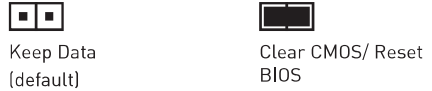
Resetting BIOS to default values
Power off the computer and unplug the power cord.
Use a jumper cap to short JBAT1 for about 5-10 seconds.
Remove the jumper cap from JBAT1.
Plug the power cord and power on the computer.
EZ Debug LED: Debug LED indicators
These LEDs indicate the status of the motherboard.
CPU - indicates CPU is not detected or failed.
DRAM - indicates DRAM is not detected or failed.
VGA - indicates GPU is not detected or failed.
Description
The MSI H110M Pro VD-Plus features the H110 chipset and supports Intel 6th and 7th Gen processors with an LGA 1151 socket. It has two DDR4 memory slots that support up to 32GB of memory with speeds of up to 2400MHz. The motherboard has one PCIe x16 slot for graphics cards and two PCIe x1 slots for expansion cards. For storage, it has four SATA III ports and one M.2 slot. The motherboard has HDMI, DVI, and VGA ports for video output and supports up to 4K resolution. It also has USB 2.0 and USB 3.0 ports for connectivity. The audio section is powered by the Realtek ALC887 codec and supports 7.1 channel surround sound. The MSI H110M Pro VD-Plus also features MSI's Military Class 4 components for improved durability and stability.
BIOS Setup
The default settings offer the optimal performance for system stability in normal conditions. You should always keep the default settings to avoid possible system damage or failure booting unless you are familiar with BIOS.
Important
BIOS items are continuously updated for better system performance. Therefore, the description may be slightly different from the latest BIOS and should be held for reference only. You could also refer to the HELP information panel for BIOS item descriptions.
The pictures in this chapter are for reference only and may vary from the product you purchased.
Entering BIOS Setup
Please refer to the following methods to enter BIOS setup.
Press the Delete key when the "Press DEL key to enter Setup Menu, F11 to enter Boot Menu" message appears on the screen during the boot process.
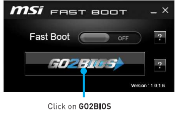
Use the MSI FAST BOOT application. Click on the GO2BIOS button and choose OK. The system will reboot and enter BIOS setup directly.
Function key
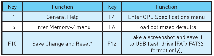
When you press F10, a confirmation window which provides the modification information appears. Select between Yes or No to confirm your choice.
MSI Motheboard H110M Pro VD-Plus Resetting BIOS
You might need to restore the default BIOS setting to solve certain problems. There are several ways to reset BIOS:
Go to BIOS and press F6 to load optimized defaults.
Short the Clear CMOS jumper on the motherboard.
Important: Please refer to the Clear CMOS Jumper section for resetting BIOS.
Updating BIOS
Updating BIOS with M-FLASH
Before updating: Please download the latest BIOS file that matches your motherboard model from the MSI website. Then save the BIOS file onto a USB flash drive.
Insert the USB flash drive that contains the update file into the computer.
Reboot the system, and then press the Del key to enter the BIOS Setup during POST.
Go to BIOS > M-FLASH > Select one file to update BIOS and ME, select a BIOS file to perform the BIOS update process.
After the flashing process is 100% complete, the system will reboot.
Updating the BIOS with Live Update 6
Before updating: Make sure the LAN driver is already installed and the internet connection is set properly.
Updating BIOS
Install and launch MSI LIVE UPDATE 6.
Select Manual scan.
Check the MB BIOS box and click on the Scan button.
Select the MB BIOS and click on
 the download icon to download and install the latest BIOS file.
Click Next and choose In Windows mode. Then click Next and Start to start updating BIOS.
After the flashing process is 100% complete, the system will restart automatically.
Software Description
Installing Windows 7/ 8.1/ 10
Power on the computer.
Insert the Windows7/ 8.1/ 10 disc into your optical drive.
Note: Due to chipset limitation, during the Windows® 7 installation process, USB optical drives or USB pen drives are not supported.Press the Restart button on the computer case.
For Windows 8.1/ 10, skip this step. For Windows® 7, access the BIOS menu Advanced > Windows OS Configuration > Windows 7 Installation and set the item to enabled, save changes, and restart.
Note: It is suggested to plug in your USB Keyboard/USB Mouse to the leftmost USB port when installing Windows® 7.Press the F11 key during the computer POST (Power-On Self Test) to get into Boot Menu.
Select your optical drive from the Boot Menu.
Press any key when the screen shows "Press any key to boot from CD or DVD..." message.
Follow the instructions on the screen to install Windows® 7/ 8.1/ 10.
Installing Drivers
Start up your computer in Windows 7/ 8.1/ 10.
Insert MSI® Driver Disc into your optical drive.
The installer will automatically appear and it will find and list all necessary drivers.
Click the Install button.
The software installation will then be in progress; after it has finished, it will prompt you to restart.
Click OK button to finish.
Restart your computer.
Installing Utilities
Before you install utilities, you must complete drivers installation.
Insert MSI® Driver Disc into your optical drive.
The installer will automatically appear.
Click the Utilities tab.
Select the utilities you want to install.
Click the Install button.
The utilities installation will then be in progress; after it has finished, it will prompt you to restart.
Click the OK button to finish.
Restart your computer.
MYSTIC LIGHT
MYSTIC LIGHT allows you to control LED lights on your motherboard and graphics cards.
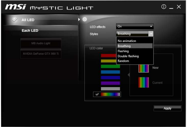
All LED - controls all LEDs on your motherboard and graphics cards.
Each LED - separately controls each segment of LEDs on your motherboard and graphics cards.
LED effects - switches LEDs on or off.
Styles - selects the LED style from the drop-down list.
LED color (optional) - allows you to change the LED color. This option depends on the motherboard you purchased.
Apply Button - applies Styles settings to LEDs.
Audio line control
Default Audio line setting in BIOS is Breathing.
After installing MYSTIC LIGHT and rebooting to OS, the default style of Audio line will switch to No animation. Once we change the Audio line style in MYSTIC LIGHT and click Apply, the software will immediately re-program the Audio line style in both BIOS and OS.
Note: Audio line styles will change to No animation if the user shuts down the MYSTIC LIGHT in OS.
Important
It is recommended to control the Audio line style by MYSTIC LIGHT.
Audio line will be in Breathing mode under DOS when you select the following styles: Flashing, Double Flashing, and Random.
MSI Motheboard H110M Pro VD-Plus Safety Information
The components included in this package are prone to damage from electrostatic discharge (ESD). Please adhere to the following instructions to ensure successful computer assembly.
Ensure that all components are securely connected. Loose connections may cause the computer to not recognize a component or fail to start.
Hold the motherboard by the edges to avoid touching sensitive components.
It is recommended to wear an electrostatic discharge (ESD) wrist strap when handling the motherboard to prevent electrostatic damage. If an ESD wrist strap is not available, discharge yourself of static electricity by touching another metal object before handling the motherboard.
Store the motherboard in an electrostatic shielding container or on an anti-static pad whenever the motherboard is not installed.
Before turning on the computer, ensure that there are no loose screws or metal components on the motherboard or anywhere within the computer case.
Do not boot the computer before installation is completed. This could cause permanent damage to the components as well as injury to the user.
If you need help during any installation step, please consult a certified computer technician.
Always turn off the power supply and unplug the power cord from the power outlet before installing or removing any computer component.
Keep this user guide for future reference.
Keep this motherboard away from humidity.
Make sure that your electrical outlet provides the same voltage as is indicated on the PSU, before connecting the PSU to the electrical outlet.
Place the power cord in such a way that people cannot step on it. Do not place anything over the power cord.
All cautions and warnings on the motherboard should be noted.
If any of the following situations arise, get the motherboard checked by service personnel:
Liquid has penetrated into the computer.
The motherboard has been exposed to moisture.
The motherboard does not work well or you cannot get it to work according to the user guide.
The motherboard has been dropped and damaged.
The motherboard has obvious signs of breakage.
Do not leave this motherboard in an environment above 60°C (140°F); it may damage the motherboard.
Troubleshooting
Common Problems and Solutions
- My graphics card is not detected: Make sure the graphics card is properly seated in the PCIe x16 slot and the power connectors are properly connected.
- My memory is not recognized: Make sure the memory modules are properly seated in the memory slots and are compatible with the motherboard.
- My system won't boot: Make sure the power supply is properly connected and the power switch is turned on.
- My system is unstable: Make sure the memory modules are properly seated and the memory speeds are set correctly in the BIOS.
MSI H110M Pro VD-Plus Pros & Cons
Pros
- Affordable price point
- Supports Intel 6th and 7th Gen processors
- Two DDR4 memory slots
- HDMI, DVI, and VGA ports for video output
- M.2 slot for fast storage
Cons
- Limited PCIe expansion slots
- Only supports up to 2400MHz memory speeds
- No built-in Wi-Fi or Bluetooth
Customer Reviews about MSI Motheboard H110M Pro VD-Plus
Customers have generally praised the MSI H110M Pro VD-Plus for its affordability and reliability. Many users have reported that the motherboard is easy to install and has performed well in their systems. However, some users have reported issues with the audio section and the lack of Wi-Fi or Bluetooth connectivity.
Faqs
What CPU socket does the MSI Motheboard H110M Pro VD-Plus support?
What type of memory is compatible with the MSI Motheboard H110M Pro VD-Plus?
What expansion slots are available on the MSI Motheboard H110M Pro VD-Plus?
How many SATA ports does the MSI Motheboard H110M Pro VD-Plus have?
What is the form factor of the MSI Motheboard H110M Pro VD-Plus?
What audio codec does the MSI Motheboard H110M Pro VD-Plus use?
How many USB ports are available on the MSI Motheboard H110M Pro VD-Plus?
Does the MSI Motheboard H110M Pro VD-Plus support dual-channel memory?
What is the BIOS version used in the MSI Motheboard H110M Pro VD-Plus?
What are the display output options on the MSI Motheboard H110M Pro VD-Plus?
Leave a Comment